EP1069341A1 - Courroie pour transmission variable en continu - Google Patents
Courroie pour transmission variable en continu Download PDFInfo
- Publication number
- EP1069341A1 EP1069341A1 EP00115241A EP00115241A EP1069341A1 EP 1069341 A1 EP1069341 A1 EP 1069341A1 EP 00115241 A EP00115241 A EP 00115241A EP 00115241 A EP00115241 A EP 00115241A EP 1069341 A1 EP1069341 A1 EP 1069341A1
- Authority
- EP
- European Patent Office
- Prior art keywords
- metal
- main surface
- belt
- metal elements
- pulley
- Prior art date
- Legal status (The legal status is an assumption and is not a legal conclusion. Google has not performed a legal analysis and makes no representation as to the accuracy of the status listed.)
- Granted
Links
- 230000005540 biological transmission Effects 0.000 title claims abstract description 20
- 229910052751 metal Inorganic materials 0.000 claims abstract description 149
- 239000002184 metal Substances 0.000 claims abstract description 84
- 238000004080 punching Methods 0.000 description 5
- 238000010521 absorption reaction Methods 0.000 description 4
- 238000010586 diagram Methods 0.000 description 4
- 230000000712 assembly Effects 0.000 description 3
- 238000000429 assembly Methods 0.000 description 3
- 230000015572 biosynthetic process Effects 0.000 description 2
- 230000003247 decreasing effect Effects 0.000 description 2
- 230000000694 effects Effects 0.000 description 1
- 238000003754 machining Methods 0.000 description 1
- 230000013011 mating Effects 0.000 description 1
- 238000000034 method Methods 0.000 description 1
Images


Classifications
-
- F—MECHANICAL ENGINEERING; LIGHTING; HEATING; WEAPONS; BLASTING
- F16—ENGINEERING ELEMENTS AND UNITS; GENERAL MEASURES FOR PRODUCING AND MAINTAINING EFFECTIVE FUNCTIONING OF MACHINES OR INSTALLATIONS; THERMAL INSULATION IN GENERAL
- F16G—BELTS, CABLES, OR ROPES, PREDOMINANTLY USED FOR DRIVING PURPOSES; CHAINS; FITTINGS PREDOMINANTLY USED THEREFOR
- F16G5/00—V-belts, i.e. belts of tapered cross-section
- F16G5/16—V-belts, i.e. belts of tapered cross-section consisting of several parts
Definitions
- the present invention relates to a belt for a continuously variable transmission, comprising a plurality of metal elements, each of which has front and rear main surfaces for contact with adjacent ones of metal elements, and which are supported on a metal ring assembly with the rear main surface of the preceding metal element being in contact with the front main surface of the succeeding metal element.
- the belt is wound around a drive pulley and a driven pulley to transmit a driving force between the pulleys.
- a stationary pulley half 04 of the drive pulley 01 and a stationary pulley half 05 of the driven pulley 02 are positioned in diagonal positions
- a movable pulley half 06 of the drive pulley 01 and a movable pulley half 07 of the driven pulley 02 are positioned in diagonal positions.
- each of the metal elements is formed into a completely flat surface, it is possible to prevent adjacent ones of the metal elements from being yawed relative to each other in a state in which they have been wound around the pulley, thereby providing an enhanced durability, and it is possible to permit the relative lateral sliding movement of the adjacent ones of the metal elements in a chord section between the pulleys, thereby absorbing the misalignment.
- a belt for a continuously variable transmission having a drive pulley and a driven pulley, comprising a plurality of metal elements, each of which has front and rear main surfaces capable of being brought into contact with adjacent ones of metal elements, and which are supported on a metal ring assembly with the rear main surface of a preceding metal element being in contact with the front main surface of a succeeding metal element.
- the belt is wound around the drive pulley and the driven pulley to transmit a driving force between the pulleys.
- One of the front and rear main surfaces of the metal elements has protrusions projecting forwards or rearwards, formed at predetermined locations at laterally opposite ends in a region near a rocking edge, respectively, and the other of the front and rear main surfaces of the metal elements has flat surface portions with which the protrusions are in contact, the flat surface portions being formed at least at laterally opposite ends in a region near a rocking edge, respectively, so that they are perpendicular to the forward and rearward directions.
- the rear main surface of the preceding metal element and the front main surface of the succeeding metal element are in contact with each other at the protrusions which project forwards or rearwards on one of the front and rear main surfaces at the predetermined locations, at the laterally opposite ends, in the region near the rocking edge, and at the flat surface portions formed on the other main surface, at least at the laterally opposite ends in the region near the rocking edge. Therefore, the metal elements can be wound around each of the pulleys in a correct attitude without yawing, whereby they can be prevented from being damaged.
- the flat surface portions on the other main surface are formed, so that they are perpendicular to the forward and rearward directions and hence, the protrusions of one of the front and rear main surfaces can freely slide laterally with respect to the flat surface portions. Therefore, even if misalignment occurs between the drive pulley and the driven pulley, the metal elements can freely slide laterally and be brought into engagement with the drive pulley or the driven pulley in a correct attitude.
- Figs. 1 to 5 show a first embodiment of the present invention.
- the definition of forward and backward directions, lateral direction and radial direction of a metal element used in the embodiments is shown in Fig. 2.
- the radial direction is defined as the radial direction of a pulley against which the metal element abuts. A location closer to the axis of revolution or rotation of the pulley is a radially inner location, and a location farther from the axis of revolution of the pulley is a radially outer location.
- the lateral direction is defined as the direction along the axis of revolution of the pulley against which the metal element abuts.
- the forward and backward directions are defined as directions along the direction of advancement of the metal element during forward traveling of a vehicle.
- Fig. 1 schematically shows the structure of a metal belt type continuously variable transmission T mounted in an automobile.
- An input shaft 3 connected to a crankshaft 1 of an engine E through a damper 2, is connected to a drive shaft 5 of the metal belt type continuously variable transmission T through a start clutch 4.
- a drive pulley 6 provided on the drive shaft 5 includes a stationary pulley half 7 secured to the drive shaft 5, and a movable pulley half 8 which can be moved toward and away from the stationary pulley half 7.
- the movable pulley half 8 is biased toward the stationary pulley half 7 by hydraulic pressure applied to an oil chamber 9.
- a driven pulley 11 is provided on a driven shaft 10 positioned parallel to the drive shaft 5, and includes a stationary pulley half 12 secured to the driven shaft 10, and a movable pulley half 13 which can be moved toward and away from the stationary pulley half 12.
- the movable pulley half 13 is biased toward the stationary pulley half 12 by hydraulic pressure applied to an oil chamber 14.
- a metal belt 15 is wound around the drive pulley 6 and the driven pulley 11 (see Fig. 2).
- the metal belt 15 comprises a large number of metal elements 32 supported on a pair of left and right metal ring assemblies 31, 31.
- Each of the metal ring assemblies 31, 31 comprises twelve metal rings 33 which are laminated one on another.
- a forward drive gear 16 and a backward drive gear 17 are rotatably supported on the driven shaft 10.
- the forward and backward drive gears 16 and 17 can be coupled selectively to the driven shaft 10 by a selector 18.
- a forward driven gear 20 meshed with the forward drive gear 16 and a backward driven gear 22 meshed with the backward drive gear 17 through a backward idling gear 21, are secured to an output shaft 19 which is disposed in parallel to the driven shaft 10.
- the revolution or rotation of the output shaft 19 is input to a differential 25 through a final drive gear 23 and a final driven gear 24, and is transmitted therefrom through left and right axles 26, 26 to driven wheels W, W.
- the driving force of the engine E is transmitted to the driven shaft 10 through the crankshaft 1, the damper 2, the input shaft 3, the start clutch 4, the drive shaft 5, the drive pulley 6, the metal belt 15 and the driven pulley 11.
- forward travel range is selected
- the driving force of the driven shaft 10 is transmitted to the output shaft 19 through the forward drive gear 16 and the forward driven gear 20, thereby allowing the vehicle to travel forwards.
- a backward travel range is selected, the driving force of the driven shaft 10 is transmitted to the output shaft 19 through the backward drive gear 17, the backward idling gear 21 and the backward driven gear 22, thereby allowing the vehicle to travel backwards.
- hydraulic pressure applied to the oil chamber 9 of the drive pulley 6 and the oil chamber 14 of the driven pulley 11 of the metal belt type continuously variable transmission T are controlled by a hydraulic pressure control unit U 2 which is operated by a command from an electronic control unit U 1 , thereby adjusting the change gear ratio continuously or in a stepless manner. That is, if hydraulic pressure applied to the oil chamber 14 of the driven pulley 11 is increased relative to hydraulic pressure applied to the oil chamber 9 of the drive pulley 6, the grove width of the driven pulley 11 is reduced, leading to an increased effective radius, and correspondingly, the groove width of the drive pulley 6 is increased, leading to a reduced effective radius.
- the change gear ratio of the metal belt type continuously variable transmission T is varied toward "LOW" continuously or in the stepless manner.
- the hydraulic pressure applied to the oil chamber 9 of the drive pulley 6 is increased relative to the hydraulic pressure applied to the oil chamber 14 of the driven pulley 11, the groove width of the drive pulley 6 is reduced, leading to an increased effective radius, and correspondingly, the groove width of the driven pulley 11 is increased, leading to a reduced effective radius. Therefore, the change gear ratio of the metal belt type continuously variable transmission T is varied toward "OD" continuously or in the stepless manner.
- each of the metal elements 32 which is formed from a metal plate by punching or stamping includes a substantially trapezoidal element body 34, a neck 36 located between a pair of left and right ring slots 35, 35 into which the metal ring assemblies 31, 31 are fitted, and a substantially triangular ear 37 connected to an upper portion of the element body 34 through the neck 36.
- the element body 34 is formed at its laterally opposite ends with a pair of pulley abutment surfaces 39, 39 capable of abutting against V-faces of the drive pulley 6 and the driven pulley 11.
- the metal element 32 is formed, at its front and rear portions in the direction of advancement, with a pair of front and rear main surfaces 40f and 40r.
- An inclined surface 42 is formed below the front main surface 40f in the travel direction with a laterally extending rocking edge 41 located therebetween.
- the ear 37 is formed, at its front and rear surfaces, with a projection 43f and a recess 43r which can be fitted to each other to connect the metal elements 32, 32 adjacent to each other in the forward and backward directions.
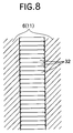
- Fig. 4 shows a cross section in a region near the rocking edge 41 of the metal element 32, namely, a cross section in a region sandwiched between the rocking edge 41 and a saddle surface 44.
- the rear main surface 40r in the region near the rocking edge 41 of the metal element 32 is formed with a flat surface portion 45 perpendicular to the forward and rearward direction.
- the front main surface 40f in the region near the rocking edge 41 of the metal element 32 is formed at its lateral opposite ends with a pair of protrusions 46, 46 (see obliquely lined portions in. Fig. 3).
- each of the protrusions, 46, 46 is set smaller than the width of each of the pair of saddle surfaces 44, 44, and the amount of forward projection of the protrusions 46, 46 is largest (approximately 10 ⁇ m) at the lateral opposite ends of the metal element 32 and is decreased therefrom toward the neck 36 down to 0 (zero).
- Such shape of the main surfaces 40f and 40r of the metal element 32 is formed by a punching or stamping die for forming the metal element 32.
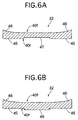
- Fig. 4 shows a state in which no forward or rearward urging force is applied between the metal elements 32. When a forward or rearward urging force is applied, the protrusions 46, 46 are compressed, resulting in a decreased projection amount.
- an urging force equal to or larger than a predetermined torque is applied, the front main surface 40f and the rear main surface 40r are brought into close contact with each other (see Fig. 7B).
- the metal elements 32 When the metal elements 32 are wound around the drive pulley 6 or the driven pulley 11, they are opened radially with respect to an axis of the drive pulley 6 or the driven pulley 11, whereby the main surfaces 40f and 40r of the ear 37 are spaced apart from each other. However, in the region near the rocking edge 41, the metal elements 32 are maintained in a state in which the flat surface portion 45 of the rear main surface 40r of the preceding metal element 32 is in contact with the left and right protrusions 46, 46 of the front main surface 40f of the succeeding metal element 32.
- Fig. 5 shows a state of the metal belt 15 which moves from the driven pulley 11 in the lower side in this figure toward the drive pulley 6 in the upper side, and the protrusions 46, 46 are provided on the front of the metal element 32 in the direction of advancement.
- the metal elements 32 exist in a chord section between an exit of the drive pulley 6 and an entrance of the driven pulley 11, the metal elements 32 are maintained in a state in which the flat surface portion 45 of the rear main surface 40r and the protrusions 46, 46 of the front main surface 40f are in contact with each other and hence, the transmission of power from the drive pulley 6 to the driven pulley 11 is conducted efficiently.
- the protrusions 46, 46 of the front main surface 40f can slide smoothly relative to the flat surface portion 45 of the rear main surface 40r, because the flat surface portion 45 is formed, so that it is perpendicular to the forward and rearward directions. Therefore, as shown in Fig. 5, the preceding and succeeding metal elements 32 can move freely in parallel in the lateral direction by the sliding movement of the flat surface portion 45 and the protrusions 46, 46, whereby the misalignment can be absorbed reliably.
- the positions of the protrusions 46, 46 of the metal elements 32 correspond to those of the lateral opposite ends of the metal element. Therefore, when the adjacent metal elements 32 are moved relative to each other in the lateral direction to absorb the misalignment, the protrusion 46 at one of the opposite ends of one of the metal elements 32 is displaced out of the rear main surface 40r of the other of the metal elements 32 and hence, the metal element 32 is slightly inclined, i.e., yawed. However, the angle of this inclination is very small, because the largest amount of projection of the protrusion 46 of the metal element 32 is as small as about 10 ⁇ m. Thus, the lateral smooth sliding movement of the metal elements 32 is not impeded.
- the flat surface portion 45 of the rear main surface 40r extends over the entire lateral region of the section near the rocking edge 41 of the metal element 32, as shown in Fig. 4.
- a pair of flat surface portions 45, 45 are formed in a laterally separated relation by formation of a recess 47 at a laterally central portion of a rear main surface 40r.
- a pair of flat surface portions 45, 45 are formed in a laterally separated relation by formation of a projection 48 at a laterally central portion of a rear main surface 40r.
- the recess 47 and the projection 48 are formed on the back side of a region indicated by mesh lines in Fig. 3.
- the flat surface portions 45, 45 of the rear main surfaces 40r may be provided in areas in which they are in contact with the protrusions 46, 46 of the front main surface 40f, namely, in areas enabling the adjacent metal elements 32 to slide laterally and smoothly.
- the projection 48 as in the third embodiment it is necessary to suppress the height of the projection 48 to a lower level (equal to or less than approximately 5 ⁇ m), so that the contact between the protrusions 46, 46 and the flat surface portions 45, 45 is not obstructed.
- a metal element 32 in the fourth embodiment is an improvement in the metal element 32 in the first embodiment, and protrusions 46, 46 of the metal element 32 are rounded. More specifically, the metal element 32 is automatically rounded at the tip ends of the protrusions 46, 46 by barreling after a punching and hence, the peak point of each of the protrusions 46, 46 is formed at a location spaced slightly inwards (at a distance of about 0.5 to 1.0 mm) apart from each of the lateral opposite ends of the metal element 32.
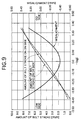
- the influence of the misalignment between the drive pulley 6 and the driven pulley 11 will be considered below with reference to Figs. 5, 9 and 10.
- the misalignment between the drive pulley 6 and the driven pulley 11 is 0.4 mm in a state in which the gear ratio is "LOW", and is ⁇ 0.4 mm in a state in which the gear ratio is 1.
- the maximum difference is equal to about 0.8 mm
- the misalignment is varied laterally 0.4 mm by 0.4 mm from a state in which the misalignment is 0 (zero).
- the plurality of metal elements 32 are moved relatively little by little in the lateral direction to absorb the misalignment, and hence, the amount of relative movement of the pair of adjacent metal elements 32 is smaller than 0.4 mm. Therefore, if the peak point of the protrusion 46 of each metal element 32 is formed at a location spaced inwards at a distance of about 0.5 to 1.0 mm apart from the lateral opposite ends of the metal element 32, as shown in Fig. 11, such peak point can be reliably brought into abutment against the flat surface portion 45 of the rear main surface 40r of the mating metal element 32 to further reliably prevent the inclination of the metal element 32.
- the fifth and sixth embodiments are improvements in the second and third embodiments shown in Figs. 6A and 6B.
- protrusions 46, 46 are rounded, so that each of the peak points thereof are formed at a location spaced inwards at a distance of about 0.5 to 1.0 mm apart from each of the laterally opposite ends of a metal element 32.
- a function and an effect similar to those in the fourth embodiment can be achieved.
- the protrusions 46, 46 are formed on the front main surface 40f of the metal element 32, and the flat surface portions 45, 45 are formed on the rear main surface 40r.
- the positional relation between the protrusions and the flat surface portions may be reversed, i.e., the protrusions 46, 46 may be formed on the rear main surface 40r, and the flat surface portions 45, 45 may be formed on the front main surface 40f.
- a pair of protrusions are formed at laterally opposite ends of a front main surface opposed to a preceding metal element, and flat surface portions are formed on a rear main surface opposed to a succeeding metal element.
- the metal elements can be wound in a correct attitude around a pulley without being yawed by the contact of the protrusions and the flat surface portions with each other, whereby they can be prevented from being damaged. Further the metal elements contacting with each other in a chord section of the metal belt can slide laterally. Thus, a misalignment between a drive pulley and a driven pulley can be absorbed.
Landscapes
- Engineering & Computer Science (AREA)
- General Engineering & Computer Science (AREA)
- Mechanical Engineering (AREA)
- Transmissions By Endless Flexible Members (AREA)
Applications Claiming Priority (2)
| Application Number | Priority Date | Filing Date | Title |
|---|---|---|---|
| JP19861599A JP3736993B2 (ja) | 1999-07-13 | 1999-07-13 | 無段変速機用ベルト |
| JP19861599 | 1999-07-13 |
Publications (2)
| Publication Number | Publication Date |
|---|---|
| EP1069341A1 true EP1069341A1 (fr) | 2001-01-17 |
| EP1069341B1 EP1069341B1 (fr) | 2004-03-24 |
Family
ID=16394146
Family Applications (1)
| Application Number | Title | Priority Date | Filing Date |
|---|---|---|---|
| EP00115241A Expired - Lifetime EP1069341B1 (fr) | 1999-07-13 | 2000-07-13 | Courroie pour transmission variable en continu |
Country Status (4)
| Country | Link |
|---|---|
| US (1) | US6409620B1 (fr) |
| EP (1) | EP1069341B1 (fr) |
| JP (1) | JP3736993B2 (fr) |
| DE (1) | DE60009217T2 (fr) |
Cited By (4)
| Publication number | Priority date | Publication date | Assignee | Title |
|---|---|---|---|---|
| US6453716B2 (en) * | 2000-03-06 | 2002-09-24 | Honda Giken Kogyo Kabushiki Kaisha | Method of blanking elements of belt for continuously variable transmission |
| NL1021661C2 (nl) * | 2002-10-16 | 2004-04-27 | Doornes Transmissie Bv | Drijfriem met dwarselementen en stansinrichting voor de vervaardiging van dwarselementen. |
| WO2006068458A1 (fr) * | 2004-12-20 | 2006-06-29 | Robert Bosch Gmbh | Courroie d'entrainement pour une transmission variable en continu |
| NL1039972C2 (en) * | 2012-12-24 | 2014-06-25 | Bosch Gmbh Robert | Transverse segment for a pushbelt for a continuously variable transmission and method for blanking it. |
Families Citing this family (12)
| Publication number | Priority date | Publication date | Assignee | Title |
|---|---|---|---|---|
| JP4065139B2 (ja) * | 2002-03-28 | 2008-03-19 | 本田技研工業株式会社 | ベルト式無段変速機 |
| ITTO20040671A1 (it) * | 2004-10-05 | 2005-01-05 | Dayco Europe Srl | Cinghia per una trasmissione variabile con continuita' |
| JP4505316B2 (ja) * | 2004-11-26 | 2010-07-21 | 本田技研工業株式会社 | 無段変速機用ベルト |
| KR101538201B1 (ko) * | 2008-12-19 | 2015-07-20 | 로베르트 보쉬 게엠베하 | 구동 벨트 |
| EP2924316A4 (fr) | 2012-11-26 | 2016-01-20 | Toyota Motor Co Ltd | Courroie de transmission à variation continue et procédé de fabrication |
| MX369638B (es) * | 2013-06-04 | 2019-11-13 | Honda Motor Co Ltd | Correa de metal para una transmisión contínuamente variable. |
| US11047451B2 (en) * | 2016-05-18 | 2021-06-29 | Aisin Aw Co., Ltd. | Transmission belt |
| JP6444355B2 (ja) * | 2016-11-04 | 2018-12-26 | 本田技研工業株式会社 | 無段変速機用金属エレメントおよび無段変速機用金属エレメントの製造方法 |
| JP6809368B2 (ja) * | 2017-05-16 | 2021-01-06 | アイシン・エィ・ダブリュ株式会社 | 無段変速機および伝動ベルト |
| JP6787494B2 (ja) * | 2017-08-14 | 2020-11-18 | アイシン・エィ・ダブリュ株式会社 | 伝動ベルト用エレメントおよび伝動ベルト |
| JP6621495B2 (ja) * | 2018-04-03 | 2019-12-18 | 本田技研工業株式会社 | 無段変速機用金属エレメントおよび無段変速機用金属エレメントの製造方法 |
| JP6683772B2 (ja) * | 2018-08-10 | 2020-04-22 | 本田技研工業株式会社 | ベルト式無段変速機用金属ベルト |
Citations (5)
| Publication number | Priority date | Publication date | Assignee | Title |
|---|---|---|---|---|
| EP0278545A1 (fr) * | 1987-01-23 | 1988-08-17 | Van Doorne's Transmissie B.V. | Courroie de transmission, élément transversal pour une courroie de transmission, procédé et dispositif de fabrication |
| US4826473A (en) * | 1986-10-30 | 1989-05-02 | Fuji Jukogyo Kabushiki Kaisha | Belt for a continuously variable transmission |
| EP0460721A1 (fr) * | 1990-06-05 | 1991-12-11 | Van Doorne's Transmissie B.V. | Elément profilé de courroie |
| JPH04362338A (ja) | 1991-05-29 | 1992-12-15 | Van Doornes Transmissie Bv | 輪郭をつけたベルト素子 |
| JPH0537068U (ja) | 1991-10-29 | 1993-05-21 | 株式会社シマノ | 伸縮式竿の嵌合構造 |
Family Cites Families (6)
| Publication number | Priority date | Publication date | Assignee | Title |
|---|---|---|---|---|
| JPS6079038U (ja) * | 1983-11-07 | 1985-06-01 | 本田技研工業株式会社 | Vベルト伝動装置 |
| US4689038A (en) * | 1984-03-26 | 1987-08-25 | Dayco Products, Inc. | Belt construction, transverse belt element therefor and method of making the same |
| JPS647936U (fr) * | 1987-07-03 | 1989-01-17 | ||
| DE3805182A1 (de) * | 1988-02-19 | 1989-08-31 | Ford Werke Ag | Profilkoerper-gliederband fuer stufenlos regelbare kegelscheiben-umschlingungsgetriebe |
| JPH0537068A (ja) | 1991-07-25 | 1993-02-12 | Sumitomo Electric Ind Ltd | 半導体レーザ |
| NL9201608A (nl) * | 1992-09-17 | 1994-04-18 | Doornes Transmissie Bv | Dwarselement voor een eindloos overbrengingsorgaan. |
-
1999
- 1999-07-13 JP JP19861599A patent/JP3736993B2/ja not_active Expired - Fee Related
-
2000
- 2000-07-12 US US09/615,053 patent/US6409620B1/en not_active Expired - Fee Related
- 2000-07-13 DE DE60009217T patent/DE60009217T2/de not_active Expired - Fee Related
- 2000-07-13 EP EP00115241A patent/EP1069341B1/fr not_active Expired - Lifetime
Patent Citations (5)
| Publication number | Priority date | Publication date | Assignee | Title |
|---|---|---|---|---|
| US4826473A (en) * | 1986-10-30 | 1989-05-02 | Fuji Jukogyo Kabushiki Kaisha | Belt for a continuously variable transmission |
| EP0278545A1 (fr) * | 1987-01-23 | 1988-08-17 | Van Doorne's Transmissie B.V. | Courroie de transmission, élément transversal pour une courroie de transmission, procédé et dispositif de fabrication |
| EP0460721A1 (fr) * | 1990-06-05 | 1991-12-11 | Van Doorne's Transmissie B.V. | Elément profilé de courroie |
| JPH04362338A (ja) | 1991-05-29 | 1992-12-15 | Van Doornes Transmissie Bv | 輪郭をつけたベルト素子 |
| JPH0537068U (ja) | 1991-10-29 | 1993-05-21 | 株式会社シマノ | 伸縮式竿の嵌合構造 |
Cited By (5)
| Publication number | Priority date | Publication date | Assignee | Title |
|---|---|---|---|---|
| US6453716B2 (en) * | 2000-03-06 | 2002-09-24 | Honda Giken Kogyo Kabushiki Kaisha | Method of blanking elements of belt for continuously variable transmission |
| NL1021661C2 (nl) * | 2002-10-16 | 2004-04-27 | Doornes Transmissie Bv | Drijfriem met dwarselementen en stansinrichting voor de vervaardiging van dwarselementen. |
| WO2004036083A3 (fr) * | 2002-10-16 | 2004-06-17 | Doornes Transmissie Bv | Courroie d'entrainement a elements transversaux et dispositif d'estampage pour produire des elements transversaux |
| WO2006068458A1 (fr) * | 2004-12-20 | 2006-06-29 | Robert Bosch Gmbh | Courroie d'entrainement pour une transmission variable en continu |
| NL1039972C2 (en) * | 2012-12-24 | 2014-06-25 | Bosch Gmbh Robert | Transverse segment for a pushbelt for a continuously variable transmission and method for blanking it. |
Also Published As
| Publication number | Publication date |
|---|---|
| DE60009217T2 (de) | 2005-01-27 |
| DE60009217D1 (de) | 2004-04-29 |
| JP3736993B2 (ja) | 2006-01-18 |
| US6409620B1 (en) | 2002-06-25 |
| JP2001027288A (ja) | 2001-01-30 |
| EP1069341B1 (fr) | 2004-03-24 |
Similar Documents
| Publication | Publication Date | Title |
|---|---|---|
| US6409620B1 (en) | Belt for continuosly variable transmission | |
| US6440025B1 (en) | Belt for continuously variable transmission | |
| EP1067311B1 (fr) | Courroie pour transmission continuellement variable | |
| EP1061285B1 (fr) | Courroie pour transmission continûment variable | |
| US6755760B2 (en) | Belt for non-stage transmissions | |
| EP1162387B1 (fr) | Courroie pour transmissions continues | |
| US6612954B2 (en) | Belt for continuously variable transmission | |
| EP1069343B1 (fr) | Courroie de transmission a reglage continu | |
| EP0984198B1 (fr) | Transmission continûment variable | |
| EP1566567A1 (fr) | Courroie metallique pour selecteur de vitesse sans fin | |
| EP1231407B1 (fr) | Courroie pour transmission continûment variable | |
| US7077775B2 (en) | Oxa(thia)zolidine compounds, process for preparation thereof and anti-inflammatory agents | |
| EP1179691B1 (fr) | Courroie pour transmission continûment variable | |
| US6406395B1 (en) | Belt for continuously variable transmission | |
| JP2003120758A (ja) | 無段変速機用ベルト |
Legal Events
| Date | Code | Title | Description |
|---|---|---|---|
| PUAI | Public reference made under article 153(3) epc to a published international application that has entered the european phase |
Free format text: ORIGINAL CODE: 0009012 |
|
| AK | Designated contracting states |
Kind code of ref document: A1 Designated state(s): DE FR GB NL |
|
| AX | Request for extension of the european patent |
Free format text: AL;LT;LV;MK;RO;SI |
|
| 17P | Request for examination filed |
Effective date: 20001229 |
|
| AKX | Designation fees paid |
Free format text: DE FR GB NL |
|
| 17Q | First examination report despatched |
Effective date: 20030213 |
|
| GRAP | Despatch of communication of intention to grant a patent |
Free format text: ORIGINAL CODE: EPIDOSNIGR1 |
|
| GRAS | Grant fee paid |
Free format text: ORIGINAL CODE: EPIDOSNIGR3 |
|
| GRAA | (expected) grant |
Free format text: ORIGINAL CODE: 0009210 |
|
| AK | Designated contracting states |
Kind code of ref document: B1 Designated state(s): DE FR GB NL |
|
| REG | Reference to a national code |
Ref country code: GB Ref legal event code: FG4D |
|
| REF | Corresponds to: |
Ref document number: 60009217 Country of ref document: DE Date of ref document: 20040429 Kind code of ref document: P |
|
| ET | Fr: translation filed | ||
| PLBE | No opposition filed within time limit |
Free format text: ORIGINAL CODE: 0009261 |
|
| STAA | Information on the status of an ep patent application or granted ep patent |
Free format text: STATUS: NO OPPOSITION FILED WITHIN TIME LIMIT |
|
| 26N | No opposition filed |
Effective date: 20041228 |
|
| PGFP | Annual fee paid to national office [announced via postgrant information from national office to epo] |
Ref country code: DE Payment date: 20080717 Year of fee payment: 9 |
|
| PGFP | Annual fee paid to national office [announced via postgrant information from national office to epo] |
Ref country code: FR Payment date: 20080718 Year of fee payment: 9 Ref country code: NL Payment date: 20080703 Year of fee payment: 9 |
|
| PGFP | Annual fee paid to national office [announced via postgrant information from national office to epo] |
Ref country code: GB Payment date: 20080716 Year of fee payment: 9 |
|
| GBPC | Gb: european patent ceased through non-payment of renewal fee |
Effective date: 20090713 |
|
| NLV4 | Nl: lapsed or anulled due to non-payment of the annual fee |
Effective date: 20100201 |
|
| REG | Reference to a national code |
Ref country code: FR Ref legal event code: ST Effective date: 20100331 |
|
| PG25 | Lapsed in a contracting state [announced via postgrant information from national office to epo] |
Ref country code: FR Free format text: LAPSE BECAUSE OF NON-PAYMENT OF DUE FEES Effective date: 20090731 |
|
| PG25 | Lapsed in a contracting state [announced via postgrant information from national office to epo] |
Ref country code: GB Free format text: LAPSE BECAUSE OF NON-PAYMENT OF DUE FEES Effective date: 20090713 |
|
| PG25 | Lapsed in a contracting state [announced via postgrant information from national office to epo] |
Ref country code: DE Free format text: LAPSE BECAUSE OF NON-PAYMENT OF DUE FEES Effective date: 20100202 |
|
| PG25 | Lapsed in a contracting state [announced via postgrant information from national office to epo] |
Ref country code: NL Free format text: LAPSE BECAUSE OF NON-PAYMENT OF DUE FEES Effective date: 20100201 |