EP1069244A2 - Méthode et dispositif pour contrôler un vibrateur de fond de trou - Google Patents
Méthode et dispositif pour contrôler un vibrateur de fond de trou Download PDFInfo
- Publication number
- EP1069244A2 EP1069244A2 EP00114397A EP00114397A EP1069244A2 EP 1069244 A2 EP1069244 A2 EP 1069244A2 EP 00114397 A EP00114397 A EP 00114397A EP 00114397 A EP00114397 A EP 00114397A EP 1069244 A2 EP1069244 A2 EP 1069244A2
- Authority
- EP
- European Patent Office
- Prior art keywords
- rotation
- leader
- vibrator
- unbalanced mass
- strand
- Prior art date
- Legal status (The legal status is an assumption and is not a legal conclusion. Google has not performed a legal analysis and makes no representation as to the accuracy of the status listed.)
- Granted
Links
- 238000000034 method Methods 0.000 title claims abstract description 12
- 238000012544 monitoring process Methods 0.000 title description 2
- 230000008878 coupling Effects 0.000 claims abstract description 6
- 238000010168 coupling process Methods 0.000 claims abstract description 6
- 238000005859 coupling reaction Methods 0.000 claims abstract description 6
- 229910000831 Steel Inorganic materials 0.000 claims abstract description 4
- 239000010959 steel Substances 0.000 claims abstract description 4
- 239000002689 soil Substances 0.000 claims description 6
- 238000005056 compaction Methods 0.000 description 3
- 230000035515 penetration Effects 0.000 description 3
- 230000002441 reversible effect Effects 0.000 description 2
- 230000015572 biosynthetic process Effects 0.000 description 1
- 238000006243 chemical reaction Methods 0.000 description 1
- 238000011038 discontinuous diafiltration by volume reduction Methods 0.000 description 1
- 230000005611 electricity Effects 0.000 description 1
- 239000010720 hydraulic oil Substances 0.000 description 1
- 230000007257 malfunction Effects 0.000 description 1
- 230000003252 repetitive effect Effects 0.000 description 1
- 239000004576 sand Substances 0.000 description 1
- 238000004904 shortening Methods 0.000 description 1
- 239000000725 suspension Substances 0.000 description 1
- XLYOFNOQVPJJNP-UHFFFAOYSA-N water Substances O XLYOFNOQVPJJNP-UHFFFAOYSA-N 0.000 description 1
Images
Classifications
-
- E—FIXED CONSTRUCTIONS
- E02—HYDRAULIC ENGINEERING; FOUNDATIONS; SOIL SHIFTING
- E02D—FOUNDATIONS; EXCAVATIONS; EMBANKMENTS; UNDERGROUND OR UNDERWATER STRUCTURES
- E02D3/00—Improving or preserving soil or rock, e.g. preserving permafrost soil
- E02D3/02—Improving by compacting
- E02D3/046—Improving by compacting by tamping or vibrating, e.g. with auxiliary watering of the soil
- E02D3/054—Improving by compacting by tamping or vibrating, e.g. with auxiliary watering of the soil involving penetration of the soil, e.g. vibroflotation
Definitions
- the invention relates to a method for compacting soils by means of a deep vibrator that goes from one to a vertical
- the unbalanced mass encircling the longitudinal axis is excited and lowered into the ground and pulled out of it again.
- the Invention a deep vibrator for performing the method with an elongated bomb-shaped housing with a longitudinal axis and a motor-driven coaxially mounted in the housing Axis of rotation and an unbalanced mass rotating with the axis of rotation.
- the compaction of uneven soils (gravel and sand) by means of Deep vibrators at great depths and in any thickness has been tried and tested.
- the application of the method to depths of 50 Meter is already running. Depths of 70 meters are targeted.
- the vibrator work is carried out by driving an unbalanced mass in the vertically suspended vibrator housing by a arranged above driven electric or hydraulic motor becomes.
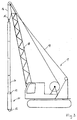
- the deep vibrator is made by screwing on a pipe string, in which the supply lines run (electricity, water, Hydraulic oil), prepared for the desired depth. That so formed aggregate is on an excavator or a special Carrier with vertical leader held over a steel cable and guided.
- the swinging and rotating suspension point is located at the top of the pipe string.
- the deep vibrator is articulated by means of an articulated coupling.
- the deep vibrator should remain at rest at the articulation point and a circular vibration with the vibrator tip below exercise.
- the movement of the vibrator is thus one Cone wrapped with the tip at the top.
- the movement of the Vibrator is determined by the frequency of rotation and the size of the unbalanced mass determines and does not necessarily correspond to the above Ideal case. Due to the rotation of the unbalanced mass, it happens a rotating torque on the vibrator housing, the to a twist of the vibrator and the pipe string and thus leads to the leader. This causes the supply lines to twist, which can be pinched off or off can tear out their fittings. This phenomenon is so far by attaching longitudinal outer swords on Housing of the deep vibrator or at least through the longitudinal one outside pipes not adequately counteracted been. Such means also increase the resistance to penetration of the deep vibrator disadvantageously.
- the soil is compacted from bottom to top. To He will lower the deep vibrator to the intended final depth either pulled up continuously or gradually in increments of 20 to 100 cm, one at each level Stops for 20 to 60 seconds.
- the compaction of the soil is naturally associated with a volume reduction that a funnel formation and concentric setting cracks around the funnel on the surface of the site and on an incline the terrain surface further points towards the funnel.
- the object of the present invention is a method and to provide a deep vibrator with which the prevents malfunctions and the penetration behavior of the deep vibrator can be improved.
- the solution to this lies in a process according to which the Unbalanced mass is driven with alternating direction of rotation.
- the direction of rotation can be changed at a fixed time or depending on the rotation of the deep vibrator towards the leader.
- the corresponding rotation can be done with suitable contactless transducers can be detected.
- a suitable deep vibrator for carrying out the process is characterized in that it is a housing of purely rotationally symmetrical External shape and a reversible drive for has the unbalanced mass.
- the deep vibrator gets an improved penetration behavior.
- the fact that it is due to the reaction moment now come to a faster twisting in the borehole can, is not critical, since monitoring means for the twist angle of the deep vibrator compared to the leader and a preferably automated reversal of the damage-free Operation ensures.
- Unbalance mass changes the direction of rotation of the reverse torque, so that the rotation that has occurred is canceled and the then occurring rotation in the opposite direction in repetitive Way is controlled and limited.
- the effective unbalance mass remains unchanged.
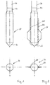
- Figure 1 is a torpedo-shaped deep vibrator according to the invention 11, the cross section of which is purely cylindrical and which shows a conical tip 12. At the top is a movable coupling 13 is provided to which a linkage section 14 connects.
- a deep vibrator 21 according to FIG State of the art shown in addition to the matching Features of a conical tip 22, a coupling 23 and a linkage section 24, lateral line guides 25, 26 and recognize radially projecting swords 27, 28 placed thereover lets counteract a rotation of the vibrator in the ground.
- the swords 27, 28 have the shape of radially projecting guide surfaces.
Landscapes
- Engineering & Computer Science (AREA)
- Structural Engineering (AREA)
- Life Sciences & Earth Sciences (AREA)
- General Life Sciences & Earth Sciences (AREA)
- Soil Sciences (AREA)
- Environmental & Geological Engineering (AREA)
- Agronomy & Crop Science (AREA)
- Mining & Mineral Resources (AREA)
- Paleontology (AREA)
- Civil Engineering (AREA)
- General Engineering & Computer Science (AREA)
- Investigation Of Foundation Soil And Reinforcement Of Foundation Soil By Compacting Or Drainage (AREA)
- Apparatuses For Generation Of Mechanical Vibrations (AREA)
- Earth Drilling (AREA)
- Placing Or Removing Of Piles Or Sheet Piles, Or Accessories Thereof (AREA)
Applications Claiming Priority (2)
| Application Number | Priority Date | Filing Date | Title |
|---|---|---|---|
| DE19930885 | 1999-07-05 | ||
| DE19930885A DE19930885C2 (de) | 1999-07-05 | 1999-07-05 | Verfahren zur Steuerung eines Tiefenrüttlers |
Publications (3)
| Publication Number | Publication Date |
|---|---|
| EP1069244A2 true EP1069244A2 (fr) | 2001-01-17 |
| EP1069244A3 EP1069244A3 (fr) | 2002-07-03 |
| EP1069244B1 EP1069244B1 (fr) | 2005-09-28 |
Family
ID=7913657
Family Applications (1)
| Application Number | Title | Priority Date | Filing Date |
|---|---|---|---|
| EP00114397A Expired - Lifetime EP1069244B1 (fr) | 1999-07-05 | 2000-07-05 | Méthode pour contrôler un vibrateur de fond de trou |
Country Status (3)
| Country | Link |
|---|---|
| EP (1) | EP1069244B1 (fr) |
| AT (1) | ATE305537T1 (fr) |
| DE (1) | DE19930885C2 (fr) |
Cited By (3)
| Publication number | Priority date | Publication date | Assignee | Title |
|---|---|---|---|---|
| EP1992742A3 (fr) * | 2007-05-16 | 2011-07-27 | Gebr. van Leeuwen Harmelen B.V. | Installation d'une fondation par vibration et liquéfaction |
| CN103439909A (zh) * | 2013-06-23 | 2013-12-11 | 四川海普工控技术有限公司 | 一种避免振冲器反复停机的监控方法 |
| US9494006B2 (en) | 2012-08-14 | 2016-11-15 | Smith International, Inc. | Pressure pulse well tool |
Families Citing this family (4)
| Publication number | Priority date | Publication date | Assignee | Title |
|---|---|---|---|---|
| DE10232314A1 (de) * | 2002-07-17 | 2004-02-05 | Bauer Spezialtiefbau Gmbh | Vorrichtung und Verfahren zum Verdichten von Böden und zur Herstellung von säulenförmigen Körpern im Boden mit Hilfe von Tiefenrüttlern |
| DE102010029010A1 (de) * | 2010-04-16 | 2011-10-20 | Alexander Degen | Tiefenrüttleranordnung mit Schneidplatte |
| CN104358248B (zh) * | 2014-11-13 | 2016-04-27 | 中国水电基础局有限公司 | 振冲碎石桩机的伸缩式导杆 |
| DE102016120382A1 (de) | 2016-10-26 | 2018-04-26 | Gmb Gmbh | Methode, Prinzip, Steuerung und Ausrüstung zur Durchführung der selbsttätigen Verdichtung von mehrphasigen Korngemischen |
Citations (3)
| Publication number | Priority date | Publication date | Assignee | Title |
|---|---|---|---|---|
| DE2629485A1 (de) | 1975-07-07 | 1977-01-20 | Kooten Bv V | Bodenvibrierer |
| DE2948403A1 (de) | 1979-12-01 | 1981-06-04 | Fritz Pollems KG Spezialtiefbau, 1000 Berlin | Vibrator zur verdichtung von erdreich |
| DE3205099A1 (de) | 1981-11-28 | 1983-06-09 | Bilfinger + Berger Bauaktiengesellschaft, 6800 Mannheim | Schlagwerk fuer einen tiefenruettler zum verdichten von erdreich |
Family Cites Families (3)
| Publication number | Priority date | Publication date | Assignee | Title |
|---|---|---|---|---|
| DE3105611C2 (de) * | 1981-02-16 | 1984-03-29 | Zoltan Thomas Dipl.-Ing. 7640 Kehl Egey | Verfahren und Vorrichtung zum Tiefverdichten |
| EP0436954B1 (fr) * | 1990-01-11 | 1994-10-05 | Seiko Kogyo Kabushiki Kaisha | Machine de forage et de malaxage à double tube et méthode d'amélioration d'un sol de fondation utilisant ladite machine de forage et de malaxage à double tube |
| DE19628769C2 (de) * | 1996-07-17 | 1998-06-10 | Bul Sachsen Gmbh | Verfahren und Einrichtung zur Tiefenverdichtung von bindigem und nichtbindigem Verdichtungsgut |
-
1999
- 1999-07-05 DE DE19930885A patent/DE19930885C2/de not_active Expired - Fee Related
-
2000
- 2000-07-05 AT AT00114397T patent/ATE305537T1/de not_active IP Right Cessation
- 2000-07-05 EP EP00114397A patent/EP1069244B1/fr not_active Expired - Lifetime
Patent Citations (3)
| Publication number | Priority date | Publication date | Assignee | Title |
|---|---|---|---|---|
| DE2629485A1 (de) | 1975-07-07 | 1977-01-20 | Kooten Bv V | Bodenvibrierer |
| DE2948403A1 (de) | 1979-12-01 | 1981-06-04 | Fritz Pollems KG Spezialtiefbau, 1000 Berlin | Vibrator zur verdichtung von erdreich |
| DE3205099A1 (de) | 1981-11-28 | 1983-06-09 | Bilfinger + Berger Bauaktiengesellschaft, 6800 Mannheim | Schlagwerk fuer einen tiefenruettler zum verdichten von erdreich |
Cited By (3)
| Publication number | Priority date | Publication date | Assignee | Title |
|---|---|---|---|---|
| EP1992742A3 (fr) * | 2007-05-16 | 2011-07-27 | Gebr. van Leeuwen Harmelen B.V. | Installation d'une fondation par vibration et liquéfaction |
| US9494006B2 (en) | 2012-08-14 | 2016-11-15 | Smith International, Inc. | Pressure pulse well tool |
| CN103439909A (zh) * | 2013-06-23 | 2013-12-11 | 四川海普工控技术有限公司 | 一种避免振冲器反复停机的监控方法 |
Also Published As
| Publication number | Publication date |
|---|---|
| EP1069244B1 (fr) | 2005-09-28 |
| ATE305537T1 (de) | 2005-10-15 |
| EP1069244A3 (fr) | 2002-07-03 |
| DE19930885A1 (de) | 2001-02-01 |
| DE19930885C2 (de) | 2003-04-24 |
Similar Documents
| Publication | Publication Date | Title |
|---|---|---|
| DE102012223992B3 (de) | Vorrichtung und Verfahren zur Bodenverdichtung und/oder Bodenverfestigung | |
| DE1634233A1 (de) | Verfahren zum Verankern von Bauwerken und Bauelementen im Erdboden mit Hilfe von Stabankern | |
| EP2322724A1 (fr) | Installation de forage d'eau souterraine et procédé d'entrée d'un élément de fondation cylindrique au fond de l'eau | |
| DE19930885C2 (de) | Verfahren zur Steuerung eines Tiefenrüttlers | |
| EP2737132B1 (fr) | Méthode de sondage du sol | |
| DE1634862A1 (de) | Ausheben von Graeben fuer in die Erde zu verlegende Mauern | |
| DE102004013790A1 (de) | Verfahren und Vorrichtung zum Eintreiben und Ausziehen von stabförmigen Elementen in den oder aus dem Boden | |
| DE10006973C2 (de) | Rüttelverdränger-Schnecke | |
| EP3230531B1 (fr) | Procédés et dispositifs d'amélioration de terrain | |
| DE102007008373A1 (de) | Verfahren und Einrichtung zur Erzeugung von tiefen Bohrungen | |
| DE19930884A1 (de) | Verfahren und Vorrichtung zur Tiefenverdichtung mit gesteuerter Frequenz- und Unwuchtänderung eines Tiefenrüttlers | |
| DE2837397A1 (de) | Vorrichtung fuer die herstellung von fundamentbohrungen u.dgl. | |
| DE4035646A1 (de) | Verfahren zum eintreiben von tragelementen in den boden | |
| DE4303742C1 (de) | Verfahren zur Entwässerung von Böden mit hohem Wasseranteil | |
| DE1224229B (de) | Verfahren zum Bohren bzw. Erweiterungsbohren im Erdreich und Vorrichtung zur Durchfuehrung des Verfahrens | |
| DE102011087096B4 (de) | Werkzeug und Verfahren zum Erstellen von Bohrlöchern mit einem nicht rotationssymmetrischen Querschnitt | |
| CN2937440Y (zh) | 挖坑机 | |
| DE3941641C1 (en) | Drive unit for foundation I beams - has ground drills within beams, retrieved after beams are properly installed | |
| DE102013226121B4 (de) | Vorrichtung und Verfahren zur Bodenverdichtung und/oder Bodenverfestigung | |
| DE244444C (fr) | ||
| DE2300212A1 (de) | Verfahren und vorrichtung zur herstellung von pfahlgruendungen unter verwendung von fertigbetonpfaehlen | |
| AT212227B (de) | Verfahren zur Herstellung von Grundwasserfassungen | |
| DE858532C (de) | Verfahren zum Loesen fest gewordener Rohre in Tiefbohrungen durch Schwingungen | |
| DE69702042T2 (de) | Verfahren zur Herstellung von Gründungspfählen unter Verwendung eines Schneckenbohrers | |
| DE102008036722A1 (de) | Verfahren, Vorrichtung und Bohrkopf zum Einbringen einer Bohrung in das Erdreich |
Legal Events
| Date | Code | Title | Description |
|---|---|---|---|
| PUAI | Public reference made under article 153(3) epc to a published international application that has entered the european phase |
Free format text: ORIGINAL CODE: 0009012 |
|
| AK | Designated contracting states |
Kind code of ref document: A2 Designated state(s): AT BE CH CY DE DK ES FI FR GB GR IE IT LI LU MC NL PT SE |
|
| AX | Request for extension of the european patent |
Free format text: AL;LT;LV;MK;RO;SI |
|
| RIN1 | Information on inventor provided before grant (corrected) |
Inventor name: KOECHER, JOHANNES, DR. Inventor name: BERG, JOACHIM, DIPL.-ING. |
|
| PUAL | Search report despatched |
Free format text: ORIGINAL CODE: 0009013 |
|
| AK | Designated contracting states |
Kind code of ref document: A3 Designated state(s): AT BE CH CY DE DK ES FI FR GB GR IE IT LI LU MC NL PT SE |
|
| AX | Request for extension of the european patent |
Free format text: AL;LT;LV;MK;RO;SI |
|
| 17P | Request for examination filed |
Effective date: 20021107 |
|
| AKX | Designation fees paid |
Designated state(s): AT CH DE FR GB LI NL |
|
| 17Q | First examination report despatched |
Effective date: 20031216 |
|
| GRAP | Despatch of communication of intention to grant a patent |
Free format text: ORIGINAL CODE: EPIDOSNIGR1 |
|
| RTI1 | Title (correction) |
Free format text: METHOD FOR MONITORING A DOWNHOLE VIBRATOR |
|
| GRAS | Grant fee paid |
Free format text: ORIGINAL CODE: EPIDOSNIGR3 |
|
| RBV | Designated contracting states (corrected) |
Designated state(s): AT CH FR GB LI NL |
|
| REG | Reference to a national code |
Ref country code: DE Ref legal event code: 8566 |
|
| GRAA | (expected) grant |
Free format text: ORIGINAL CODE: 0009210 |
|
| AK | Designated contracting states |
Kind code of ref document: B1 Designated state(s): AT CH FR GB LI NL |
|
| PG25 | Lapsed in a contracting state [announced via postgrant information from national office to epo] |
Ref country code: GB Free format text: LAPSE BECAUSE OF FAILURE TO SUBMIT A TRANSLATION OF THE DESCRIPTION OR TO PAY THE FEE WITHIN THE PRESCRIBED TIME-LIMIT Effective date: 20050928 |
|
| REG | Reference to a national code |
Ref country code: GB Ref legal event code: FG4D Free format text: NOT ENGLISH |
|
| REG | Reference to a national code |
Ref country code: CH Ref legal event code: EP |
|
| GBV | Gb: ep patent (uk) treated as always having been void in accordance with gb section 77(7)/1977 [no translation filed] |
Effective date: 20050928 |
|
| PG25 | Lapsed in a contracting state [announced via postgrant information from national office to epo] |
Ref country code: LI Free format text: LAPSE BECAUSE OF NON-PAYMENT OF DUE FEES Effective date: 20060731 Ref country code: CH Free format text: LAPSE BECAUSE OF NON-PAYMENT OF DUE FEES Effective date: 20060731 |
|
| PLBE | No opposition filed within time limit |
Free format text: ORIGINAL CODE: 0009261 |
|
| STAA | Information on the status of an ep patent application or granted ep patent |
Free format text: STATUS: NO OPPOSITION FILED WITHIN TIME LIMIT |
|
| 26N | No opposition filed |
Effective date: 20060629 |
|
| EN | Fr: translation not filed | ||
| PG25 | Lapsed in a contracting state [announced via postgrant information from national office to epo] |
Ref country code: FR Free format text: LAPSE BECAUSE OF FAILURE TO SUBMIT A TRANSLATION OF THE DESCRIPTION OR TO PAY THE FEE WITHIN THE PRESCRIBED TIME-LIMIT Effective date: 20061124 |
|
| REG | Reference to a national code |
Ref country code: CH Ref legal event code: PL |
|
| PG25 | Lapsed in a contracting state [announced via postgrant information from national office to epo] |
Ref country code: AT Free format text: LAPSE BECAUSE OF NON-PAYMENT OF DUE FEES Effective date: 20060705 |
|
| PG25 | Lapsed in a contracting state [announced via postgrant information from national office to epo] |
Ref country code: FR Free format text: LAPSE BECAUSE OF FAILURE TO SUBMIT A TRANSLATION OF THE DESCRIPTION OR TO PAY THE FEE WITHIN THE PRESCRIBED TIME-LIMIT Effective date: 20050928 |
|
| PGFP | Annual fee paid to national office [announced via postgrant information from national office to epo] |
Ref country code: NL Payment date: 20170726 Year of fee payment: 18 |
|
| REG | Reference to a national code |
Ref country code: NL Ref legal event code: MM Effective date: 20180801 |
|
| PG25 | Lapsed in a contracting state [announced via postgrant information from national office to epo] |
Ref country code: NL Free format text: LAPSE BECAUSE OF NON-PAYMENT OF DUE FEES Effective date: 20180801 |