EP1065007B1 - Aufsatz für eine Abgabepistole - Google Patents
Aufsatz für eine Abgabepistole Download PDFInfo
- Publication number
- EP1065007B1 EP1065007B1 EP00305316A EP00305316A EP1065007B1 EP 1065007 B1 EP1065007 B1 EP 1065007B1 EP 00305316 A EP00305316 A EP 00305316A EP 00305316 A EP00305316 A EP 00305316A EP 1065007 B1 EP1065007 B1 EP 1065007B1
- Authority
- EP
- European Patent Office
- Prior art keywords
- blocking
- opening
- caulking
- cartridge
- nozzle
- Prior art date
- Legal status (The legal status is an assumption and is not a legal conclusion. Google has not performed a legal analysis and makes no representation as to the accuracy of the status listed.)
- Expired - Lifetime
Links
Images


Classifications
-
- B—PERFORMING OPERATIONS; TRANSPORTING
- B05—SPRAYING OR ATOMISING IN GENERAL; APPLYING FLUENT MATERIALS TO SURFACES, IN GENERAL
- B05C—APPARATUS FOR APPLYING FLUENT MATERIALS TO SURFACES, IN GENERAL
- B05C17/00—Hand tools or apparatus using hand held tools, for applying liquids or other fluent materials to, for spreading applied liquids or other fluent materials on, or for partially removing applied liquids or other fluent materials from, surfaces
- B05C17/005—Hand tools or apparatus using hand held tools, for applying liquids or other fluent materials to, for spreading applied liquids or other fluent materials on, or for partially removing applied liquids or other fluent materials from, surfaces for discharging material from a reservoir or container located in or on the hand tool through an outlet orifice by pressure without using surface contacting members like pads or brushes
- B05C17/00503—Details of the outlet element
- B05C17/00516—Shape or geometry of the outlet orifice or the outlet element
-
- B—PERFORMING OPERATIONS; TRANSPORTING
- B05—SPRAYING OR ATOMISING IN GENERAL; APPLYING FLUENT MATERIALS TO SURFACES, IN GENERAL
- B05C—APPARATUS FOR APPLYING FLUENT MATERIALS TO SURFACES, IN GENERAL
- B05C17/00—Hand tools or apparatus using hand held tools, for applying liquids or other fluent materials to, for spreading applied liquids or other fluent materials on, or for partially removing applied liquids or other fluent materials from, surfaces
- B05C17/005—Hand tools or apparatus using hand held tools, for applying liquids or other fluent materials to, for spreading applied liquids or other fluent materials on, or for partially removing applied liquids or other fluent materials from, surfaces for discharging material from a reservoir or container located in or on the hand tool through an outlet orifice by pressure without using surface contacting members like pads or brushes
- B05C17/00596—The liquid or other fluent material being supplied from a rigid removable cartridge having no active dispensing means, i.e. the cartridge requiring cooperation with means of the handtool to expel the material
-
- E—FIXED CONSTRUCTIONS
- E04—BUILDING
- E04F—FINISHING WORK ON BUILDINGS, e.g. STAIRS, FLOORS
- E04F21/00—Implements for finishing work on buildings
- E04F21/165—Implements for finishing work on buildings for finishing joints, e.g. implements for raking or filling joints, jointers
-
- E—FIXED CONSTRUCTIONS
- E04—BUILDING
- E04F—FINISHING WORK ON BUILDINGS, e.g. STAIRS, FLOORS
- E04F21/00—Implements for finishing work on buildings
- E04F21/165—Implements for finishing work on buildings for finishing joints, e.g. implements for raking or filling joints, jointers
- E04F21/1652—Implements for finishing work on buildings for finishing joints, e.g. implements for raking or filling joints, jointers for smoothing and shaping joint compound to a desired contour
-
- E—FIXED CONSTRUCTIONS
- E04—BUILDING
- E04F—FINISHING WORK ON BUILDINGS, e.g. STAIRS, FLOORS
- E04F21/00—Implements for finishing work on buildings
- E04F21/165—Implements for finishing work on buildings for finishing joints, e.g. implements for raking or filling joints, jointers
- E04F21/1655—Implements for finishing work on buildings for finishing joints, e.g. implements for raking or filling joints, jointers for finishing corner joints
Definitions
- the invention relates to a caulking accessory for use with a caulking cartridge and caulking gun, the accessory being particularly adapted for sealing cracks in concrete or other surfaces.
- a caulking cartridge for use with a conventional caulking gun comprises a cylindrical tube containing a plastic sealant material, and a nozzle or spout extending axially from an end face of the tube.
- the caulking cartridge is inserted into the caulking gun, and the nozzle is cut obliquely at an appropriate location to provide an obliquely cut tip of a size sufficient to produce a sealant bead of a desired size for the crack or cavity to be filled.
- This simple approach has many limitations and there are many patents disclosing devices which cooperate with the conventional caulking cartridge nozzle to simplify application of the sealant, and/or to improve the resulting application of sealant.
- U.S. Patent 5,017,113 (Heaton et al.) discloses a filleting attachment for a conventional caulking gun for use in corners.
- the nozzle of the conventional cartridge is cut and then inserted in a complementary tapered nozzle of the attachment to discharge sealant into the attachment.
- the attachment has an integrally moulded triangular shaped plate as a distal end thereof which engages walls of a 90 degree corner so as to guide the nozzle and simultaneously to shape the bead of sealant discharged from the nozzle.
- the attachment has a simple annular end flange for fitting between a generally annular end flange of the conventional caulking gun and an end face of the caulking cartridge.
- U.S. Patent 4,946,081 discloses an applicator for a sealant cartridge having a discharge nozzle with a semi-cylindrical tubular portion disposed perpendicularly to a distal end of the nozzle.
- the tubular portion has an open end to discharge excess sealant therethrough to provide a flow indicator ensuring adequate filling of the crack.
- the applicator is screw-threaded onto a sleeve extending from the outer face of the cartridge, and thus is specifically adapted for use with a cartridge having complementary threads or an interference fit, or other means of securing the applicator to the opening of the sealant cartridge.
- nozzles of common, conventional sealant cartridges are generally similar in size and taper, and thus many of the applicators or accessories designed to be used with such cartridges tend to rely on an interference fit between the applicator or accessory and the cartridge nozzle. It is often difficult to maintain an adequate seal using an interference fit, and thus inadvertent sealant leakage can occur between the nozzle and the applicator, especially if higher sealant pressure than normal is attained. Also, to attain adequate penetration of sealant into deep cracks, is advantageous to generate high sealing pressures, but these higher pressures cannot be attained if excessive leakage occurs between the nozzle and the applicator.
- US-A-5,257,486 discloses a nozzle for injecting a sealant into a crack, the sealant nozzle including a positioning spider at its outlet end.
- the spider includes a plurality of radial lugs which bend about flex hinges enabling the spider to automatically conform to a range of hole sizes.
- DE-A-19547035 discloses a dispenser having a driving section with a sliding thrust member which is connected to an interchangeable tube containing a bag, and which has an outlet for material at a forward end.
- the tube outlet can be formed by one or more flaps hingeable between open and shut positions.
- the invention reduces the difficulties and disadvantages of the prior art by providing a simple, caulking device which can be manufactured using conventional plastic injection die technology for a relatively low cost and is easily adaptable to the conventional caulking gun and cartridge.
- the device provides a secure and simple means for attachment to the caulking gun and cartridge, thus reducing relative movement therebetween.
- the device has a novel seal which cooperates with the caulking cartridge nozzle in such a way that as sealant pressure increases, the seal engages the nozzle more tightly, thus enhancing sealing.
- the device cooperates with most commercially available caulking guns and cartridges and can generate relatively high pressures for injection into relatively large cracks, particularly those found in concrete, building surfaces, etc.
- a caulking device is for use with a caulking gun and comprises a body, a blocking portion and a connecting portion.
- the body has distal and proximal end portions, and a body opening extending between the end portions, the body opening being cooperable with a nozzle of a caulking cartridge.
- the blocking portion is located adjacent the distal end portion of the body, communicates with the body opening, and has a blocking surface cooperable with the surface to be sealed.
- the connecting portion is located adjacent the proximal end portion of the body and has a pair of moveable arms. The arms are located on opposite sides of the body opening and are cooperable with the caulking gun and caulking cartridge so as to be retained on the gun.
- the body opening has an opening axis, an opening sidewall and an annular flange with a flexible flange lip, the annular flange extending inwardly from the opening sidewall to the lip.
- the lip has a size and flexibility sufficient to cooperate with the nozzle of the caulking cartridge to form a seal therewith.
- the arms of the connecting portion are hinged to the body to permit movement relative thereto between operable and inoperable positions.
- the arms are hinged with respect to the body about respective hinges which are disposed parallel to each other, the hinges having respective hinge axes which are parallel to each other and disposed generally perpendicularly to the opening axis.
- each arm has a distal arm portion, a proximal arm portion and an intermediate arm portion.
- the distal arm portion cooperates with a caulking cartridge and the caulking gun and the proximal arm portion cooperates with the hinge.
- the intermediate arm portion interconnects the distal and proximal arm portions and is shaped to engage a portion of the nozzle when the arm is in the operative position thereof.
- the distal arm portion is disposed generally perpendicularly to the intermediate arm portion and the intermediate arm portion has a concave inner face which is disposed generally concentrically of the body opening when the arm is in the operative position thereof.
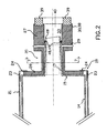
- the first embodiment 10 of a caulking accessory or device is for use for sealing cracks on flat surfaces and is shown cooperating with a conventional caulking cartridge 11 and a caulking gun 12 .
- the caulking cartridge has a tubular body 14 having an annular end face 15 and a tapered nozzle or spout 17 extending axially therefrom to a cut end 18 .
- the caulking gun 12 is a "skeleton body” type and has an annular end flange 19 and a plurality of axially extending body strips 21 which cooperate with other portions of the gun and cartridge to apply pressure to the cartridge to force sealant therefrom through the nozzle 17 as is well known.
- the end flange 19 is L-sectioned and comprises a cylindrical portion 23 and an integral planar portion 24 extending therefrom to provide a clearance opening to receive nozzle 17 extending from the end face 15 .
- the first embodiment 10 comprises a body 27 having a proximal end portion 29 located on the side of the body closest to the cartridge 11 , and a distal end portion 30 located at an opposite end of the body remote from the cartridge.
- the body has a body opening 33 extending between the end portions, the body opening cooperating with the nozzle 17 of the caulking cartridge as will be described.
- the first embodiment further comprises a connecting portion 35 located adjacent the proximal end portion 29 of the body, and a blocking portion 37 located adjacent the distal end portion 30 .
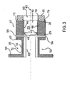
- the blocking portion 37 has a planar rectangular blocking plate 38 with a resilient blocking surface 39 which can cooperate with the surface to be sealed, as will be described with the reference to Figures 8 and 9 .
- the blocking plate has a blocking plate opening 40 which communicates with the body opening to receive sealant as will be described.
- the body opening 33 has an opening axis 45 , an opening sidewall 46 and an annular flange 48 with a flexible flange lip 49 .
- the annular flange extends inwardly from the opening sidewall to the lip and is inclined towards the distal end portion 30 of the body for reasons to be described.
- the connecting portion 35 has first and second movable arms located on opposite sides of the body opening 33 and connected to the proximal end portion 29 . As will be described, the arms cooperate with the caulking gun and caulking cartridge so as to be retained on the gun in a manner that is more secure than the conventional annular flange of some prior art caulking accessories.
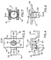
- the arms 51 and 52 of the connecting portion are shown in an operative position which permits cooperation with the caulking gun, whereas in Figures 4 - 6 the arms are shown in an inoperable position.
- the present invention is manufactured using cavity die injection techniques, and to simplify die design and manufacture, the device 10 is injected with the arms disposed in the inoperative position as shown in Figures 4 - 6 .
- the arms 51 and 52 are hinged with respect to the body 27 about respective first and second hinges 55 and 56 which are disposed parallel to each other, i.e. the hinges have undesignated respective hinge axes which are disposed parallel to each other and are also disposed generally perpendicularly to the opening axis 45 .
- the hinges 55 and 56 are injection molded concurrently with other portions of the device, and are thin portions of flexible plastic material, commonly referred to as "living" or “film” hinges. Such hinges can be reversed many times and are simple and low cost to produce.
- the arms 51 and 52 are similar to each other and thus only the first arm 51 will be described in detail.
- the arm 51 has a distal arm portion 59 , a proximal arm portion 60 and an intermediate arm portion 61 interconnecting the distal and proximal arm portions.
- the distal arm portion 59 and proximal arm portion 60 are generally flat plates and extend in similar directions from the intermediate arm portion 61 .
- the portions 59 and 60 are disposed generally parallel to each other, and are also disposed generally perpendicularly to the intermediate arm portion.
- the distal arm portion 59 cooperates with the caulking cartridge and caulking gun, as will be described with respect to Figure 2
- the proximal arm portion 60 is connected to the hinge 55 so as to cooperate therewith.
- the intermediate arm portion 61 is generally straight and has a concave inner face 65 , and when the arm 51 is in the operative position thereof, the inner face 65 is disposed generally concentrically of the body opening 33 and is shaped to engage a portion of the nozzle 17 , the opening axis 45 and nozzle being shown in broken out line in Figure 6 in relative operative positions.
- the nozzle 17 is not normally positioned adjacent the intermediate portion when the device is in the inoperative position as shown in Figure 6 .
- the distal arm portions, e.g. 59 when the arms are in the operative position, are generally co-planar with each other.
- the intermediate arm portions, e.g. 61 are disposed parallel to each other and, as best seen in Figure 7 , embrace opposite sides of the nozzle 17 with concave inner surfaces thereof concentric with the axis 45 .
- the proximal arm portion 60 has a length 68 defined by spacing between the hinge axis 55 and the intermediate portion 61 .
- the hinge axis 55 is spaced from a closest adjacent sidewall 70 of the body opening 33 by a distance 72 which is approximately equal to the length 68 of the proximal end portion.
- the blocking plate 38 has a pair of generally parallel peripheral walls 75 and 76 extending outwardly therefrom, and an annular inner wall 78 extending around the opening 33 .
- a generally rectangular sheet of expanded foam plastic material 81 is secured, e.g. by gluing, to the outer face of the blocking plate 38 and has an opening 82 generally concentric with the opening axis 45 and complementary to the inner wall 78 .
- the walls 75 , 76 , and 78 stabilize edges of the foamed plastic material 81 and have a depth less than thickness of the foamed plastic material so that the plastic material stands proud of the edges.
- the device 10 is usually supplied to the user in the inoperative position as shown in Figures 4 - 6 with the arms 51 and 52 extending outwardly but with the foamed plastic material 81 fitted as shown in Figure 3 .
- the user cuts the nozzle 17 at the cut end 18 which is to be disposed between the annular flange 48 and the distal end portion 30 of the body.
- a typical distance between the flange lip 49 and the distal end portion 30 is about 1 cm, the actual location of the cut end 18 , or the angle of the cut, is not very critical when compared to prior art cutting of a caulking cartridge nozzle.
- the nozzle 17 is inserted through the flange 48, and the lip 49 of the flange has a size and flexibility sufficient to cooperate with the nozzle 17 to form a seal therewith.
- the arms 51 and 52 are rotated about respective hinges 55 and 56 so that concave inner portions of the intermediate arm portions, e.g.
- the arm 51 embrace diametrically opposite portions of the nozzle sidewall, as best seen in Figures 2 and 7 .
- the user then inserts the cartridge and the attached accessory 10 into the caulking gun so that the distal arm portions, e.g. 59 , are inserted into a small space between the annular end face 15 of the cartridge and the annular planar portion 24 of the end flange 19 of the caulking gun. Any pressure applied to the sealant within the cartridge by the caulking gun results in movement of the end face 15 to squeeze the distal arm portions between the end face and the end flange 19 to provide a secure fit therewith.
- the arms are of sufficient resiliency to accommodate slight variations in dimensions and taper of the nozzle 17 and yet firmly embrace at least larger diameter portions of the nozzle so that the nozzle and arm portions form a substantially stiff combination to resist compression and any twisting forces that might arise during operation.
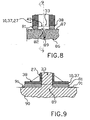
- a portion of concrete 86 has an uneven surface 87 with a crack 89 extending inwardly from the surface, the crack requiring filling with the sealant from the cartridge.
- the blocking portion 37 is located above the crack so that the body opening is generally aligned with the crack, and the foamed plastic material 81 straddles the crack as best seen in Figure 8 .
- An axial force is applied to the caulking gun to deflect the material 81 so that it distorts to accommodate the uneven surface 87 , so as to provide an effective seal therewith on opposites sides of the crack.
- the caulking gun is then operated to inject sealant material 90 through the nozzle of the cartridge, the body opening 33 , the blocking plate opening 40 and the opening 82 in the foamed material 81 , and then into the crack.
- Sealant is dispersed within the crack and, depending on the geometry of the crack, the sealant tends to fill the crack immediately adjacent the nozzle and then it is displaced laterally along the crack to eventually approach the concrete surface adjacent edges of the crack.
- the blocking plate and resiliency in the foamed material 81 to accommodate the uneven surface serve as a block to essentially prevent any sealant 90 from moving outwardly above the surface 87 of the concrete, but excess sealant, designated 91 , can exude beyond edges of the blocking plate, thus indicating that immediately adjacent portions of the crack are filled.
- the enhanced sealing arises because the lip has a sufficient size and flexibility which, when subjected to the sealant pressure, is forced towards the proximal end portion and inwardly towards the opening axis to increase sealing force acting on the nozzle of the caulking cartridge.
- the higher the sealing pressure generated in the opening 33 the better the sealing between the flange and the nozzle.
- the caulking gun can operate at higher pressures than normal and such pressures permit improved penetration of sealant into the crack, which improves adhesion of the sealant to surfaces of the crack, which are generally rough and can provide keying if the sealant is forced strongly against such surfaces.
- the high pressure tends to reduce air entrapment within the sealant which improves longevity of the seal.
- the operator moves the device and gun along the crack a short distance so that the blocking plate slightly overlaps the previously injected sealant, and the process is repeated until sealant appears again adjacent an edge of the blocking plate. This indicates that the crack on that side of the previously applied sealant has now been filled with the recently applied sealant.
- the device and caulking gun is then moved again, and the process is repeated incrementally along the crack until the crack is filled.
- the method of the invention comprises a series of discrete injections of sealant at closely spaced locations along the crack, space between the locations being determined by size of the blocking plate.
- the sealant projects somewhat from the crack, often as a series of regular projections and thus it requires smoothing before the sealant cures. Smoothing of the relatively rough sealant can be performed using a spatula, trowel or other sealant applicator.
- the first embodiment of the device is shown for use with a "skeleton type" caulking gun but it can also be used with an alternative earlier design of caulking gun in which the annular end flange 19 is eliminated and an end disc with a radial slot substituted.
- a semi-cylindrical shell extends along the body of this type of gun to partially enclose the cartridge, thus eliminating the separate axially disposed body strips 21 .
- a procedure to attach the device 10 to the alternative caulking gun is generally similar to that as previously described, as follows.
- the arms 51 and 52 are swung about the respective hinges to enclose the nozzle 17 of the caulking cartridge (see Figures 2 and 7 ) and the cartridge and device are then moved concurrently laterally into the radial slot of the disc of the caulking gun.
- the distal arm portions are fitted between the end disc of the caulking gun and the end face of the cartridge and the intermediate arm portions are received in the slot of the end disc.
- the device 10 is for use in sealing cracks on relatively flat or planar surfaces, e.g. 87 of Figure 8 , and clearly the shape of the blocking portion is selected to conform to the shape of the surface to be sealed.
- convex or concave surfaces would have corresponding complementary concave and convex blocking portions respectively.
- a relatively common application of the invention is for sealing cracks in inside corners in which intersecting walls meet at 90 degrees. This requires a complementary V-shaped blocking portion to be described with respect to Figures 10 - 12 as follows.
- the second embodiment 97 of the invention has a body 99 , a connecting portion 100 and a blocking portion 101 .
- the connecting portion has first and second arms 103 and 104 which are essentially identical to the arms 51 and 52 and function identically.
- the body 99 has distal and proximal end portions 107 and 108 and a body opening 109 extending between the end portions as previously described.
- the arms are hinged to the proximal end portion similarly to the first embodiment, and the body opening 109 has a similar annular flange 110 .
- This distal end portion 107 is shaped to be complementary to the blocking portion 101 and, in contrast to the first embodiment which has a flat blocking portion, the alternative blocking portion is generally V-shaped to engage a right-angled internal corner.
- the blocking portion 101 comprises a pair of blocking plates 112 and 113 intersecting at an angle 115 to each other at a blocking corner 117 .
- the blocking corner has a blocking corner axis 118 and the blocking plates intersect each other perpendicularly, i.e. the angle 115 is 90 degrees.
- the body opening 109 has a body opening axis 120 which intersects the blocking corner axis 118 perpendicularly.
- the blocking plates 112 and 113 have peripheral walls 122 and 123 respectively, and a pair of projections 125 extend from the blocking corner outwardly and generally parallel to the body opening axis 120 .
- a rectangular sheet of resilient foamed plastic foamed material 127 is foamed and bonded to the two blocking plates and has an opening 129 generally complementary to the body opening 109 as it penetrates the blocking plates.
- the material 127 located on the plates 112 and 113 by the walls 122 and 123 and the projection 125 .
- the resilient foamed material 127 provides a resilient blocking surface to accommodate uneven surfaces to be sealed and is functionally equivalent to the resilient foamed plastic material 81 used in the first embodiment.
- Operation of the second embodiment is essentially identical to the first in that the second embodiment is moved incrementally along a crack adjacent a corner to apply sealant under elevated pressure to the crack as described with respect to the first embodiment.
Landscapes
- Engineering & Computer Science (AREA)
- Architecture (AREA)
- Civil Engineering (AREA)
- Structural Engineering (AREA)
- Mechanical Engineering (AREA)
- Physics & Mathematics (AREA)
- Geometry (AREA)
- Coating Apparatus (AREA)
- Manufacturing Of Electric Cables (AREA)
- Braking Systems And Boosters (AREA)
- Magnetic Heads (AREA)
Claims (18)
- Dichtvorrichtung (10, 97) zur Verwendung mit einer Dichtpistole (12), wobei die Vorrichtung umfaßt:(a) einen Körper (27, 99), der distale und proximale Endabschnitte (29, 30, 107, 108) hat und eine Körperöffnung (33, 109), die zwischen den Endabschnitten verläuft, wobei die Körperöffnung zusammenwirken kann mit einer Düse (17), einer Dichtmittelkartusche (11),(b) einen Blockierabschnitt (37, 101), der an dem distalen Endabschnitt (30, 107) des Körpers (27, 99) angrenzend, angeordnet ist, wobei der Blockierabschnitt (37, 101) mit der Körperöffnung (23, 109) kommuniziert und eine Blockieroberfläche (38, 112, 113) hat, die mit einer zu dichtenden Oberfläche zusammenwirken kann, und(c) einen Verbindungsabschnitt (35, 100), der an dem proximalen Endabschnitt (29, 108) des Körpers (27, 99) angrenzend, angeordnet ist, wobei der Verbindungsabschnitt ein Paar bewegliche Arme (51, 52, 103, 104) hat und die Arme an gegenüberliegenden Seiten der Körperöffnung angeordnet sind und mit der Dichtmittelpistole (12) und der Dichtmittelkartusche (11) zusammenwirken können, um an der Pistole (12) gehalten zu sein.
- Vorrichtung (10, 97), nach Anspruch 1, bei welcher:(a) die Körperöffnung (33, 109) eine Öffnungsachse (45, 120), eine Öffnungsseitenwand (46) und einen ringförmigen Flansch (48) mit einer elastischen Flanschlippe (49) hat, wobei der ringförmige Flansch (48) von der Öffnungsseitenwand einwärts zu der Lippe (49) verläuft, wobei die Lippe (49) eine Größe und Elastizität hat, die ausreicht für ein Zusammenwirken mit der Düse (17) der Dichtmittelkartusche (11), um damit eine Dichtung auszubilden.
- Vorrichtung (10, 97) nach Anspruch 2, bei welcher:(a) die Lippe (49) des ringförmigen Flansches (48) geneigt ist in Richtung des distalen Endabschnitts (30, 107) des Körpers (27, 99), um in Richtung der Öffnungsachse (45, 120) einwärts gezwungen zu werden, wenn sie einem dichtendem Druck unterworfen wird.
- Vorrichtung (10, 97) nach Anspruch 1, bei welcher:(a) die Arme (51, 52, 103, 104) des Verbindungsabschnitts (35, 100) angelenkt sind an dem Körper (27, 99), um diesbezüglich eine Relativbewegung zwischen einer betrieblichen und einer nicht-betrieblichen Stellung zu ermöglichen.
- Vorrichtung (10, 97) nach Anspruch 4, bei welcher:(a) die Arme (51, 52, 103, 104) bezüglich des Körpers (27, 99) um jeweilige Anlenkungsstellen (55, 56) angelenkt sind, die parallel zueinander angeordnet sind.
- Vorrichtung (10, 97) nach Anspruch 5, bei welcher:(a) die Körperöffnung (33, 109) eine Öffnungsachse (45, 120) hat und(b) die Anlenkungsstellen (55, 56) jeweilige Schwenkachsen haben, die zueinander parallel und im allgemeinen senkrecht zu der Öffnungsachse (45, 120) angeordnet sind.
- Vorrichtung (10, 97) nach Anspruch 5, bei welcher jeder Arm (51, 52, 103, 104) aufweist:(a) einen distalen Armabschnitt (49) zum Zusammenwirken mit der Dichtmittelkartusche (11) und der Dichtpistole (12),(b) einen proximalen Armabschnitt (60), der mit der Anlenkungsstelle (55, 56) zusammenwirkt, und(c) einen zwischenliegenden Armabschnitt (61), welcher den distalen und den proximalen Armabschnitt (59, 60) miteinander verbindet und derart gestaltet ist, daß er mit einem Abschnitt der Düse (17) in Eingriff steht, wenn der Arm (51,52, 103, 104) sich in seiner betrieblichen Stellung befindet.
- Vorrichtung (10, 97) nach Anspruch 7, bei welcher:(a) der distale Armabschnitt (59) im allgemeinen senkrecht zu dem zwischenliegenden Armabschnitt (61) angeordnet ist, und(b) der zwischenliegende Armabschnitt (61) eine konkave Innenfläche (65) hat, die im allgemeinen konzentrisch zu der Körperöffnung (33, 109) angeordnet ist, wenn sich der Arm (51, 52, 103, 104) in seiner betrieblichen Stellung befindet.
- Vorrichtung (10, 97) nach Anspruch 8, bei welcher:(a) der distale Armabschnitt (59) eine flache Platte zur Anordnung zwischen der Dichtmittelkartusche (11) und der Dichtpistole (12) ist.
- Vorrichtung (10, 97) nach Anspruch 7, bei welcher:(a) der distale Armabschnitt (59) und der proximale Armabschnitt (60) im allgemeinen parallel zueinander angeordnet sind.
- Vorrichtung (10, 97) nach Anspruch 7, bei welcher:(a) der distale Armabschnitt (59) und der proximale Armabschnitt (60) von dem zwischenliegenden Armabschnitt (61) in gleiche Richtungen verlaufen.
- Vorrichtung (10, 97) nach Anspruch 7, bei welcher:(a) der proximale Armabschnitt (60) eine Länge (68) hat, die definiert wird durch den Abstand zwischen der Schwenkachse (55) und dem zwischenliegenden Abschnitt (61), und(b) die Schwenkachse (55) des Armes (60) von einem nächsten Abschnitt der Seitenwand (70) der Körperöffnung (33) um eine Länge (72) beabstandet ist, die etwa gleich der Länge (68) des proximalen Endabschnitts (60) ist.
- Vorrichtung (10) nach Anspruch 1, bei welcher:(a) die Blockieroberfläche (39) des Blockierteils (37) im allgemeinen planar und im allgemeinen senkrecht zu der Körperöffnung (33) angeordnet ist.
- Vorrichtung (97) nach Anspruch 1, bei welcher:(a) das Blockierteil (101) ein Paar Blockierplatten (112, 113) umfaßt, die einander unter einem Winkel (115) bei einer Blockierecke (117) schneiden, wobei die Blockierecke (117) eine Blockiereckenachse (118) hat, und(b) die Körperöffnung (109) eine Öffnungsachse (120) hat, welche die Blockiereckenachse (118) schneidet.
- Vorrichtung (97) nach Anspruch 14, bei welcher:(a) die Blockierplatten (112, 113) einander unter einem Winkel von etwa 90° schneiden.
- Vorrichtung (97) nach Anspruch 14, bei welcher:(a) die Blockierachse (118) und die Körperöffnungsachse (120) senkrecht zueinander stehen.
- Vorrichtung (10, 97) nach Anspruch 1, bei welcher:(a) die Blockieroberfläche (38, 112, 113) elastisch ist, um ungleiche, abzudichtende Oberflächen aufzunehmen.
- Vorrichtung (10, 97) nach Anspruch 1, des weiteren aufweisend:(a) eine Schicht aus elastischem Material (39, 127), die an dem Blockierteil (37, 101) befestigt ist, um eine elastische Blockieroberfläche vorzusehen zur Aufnahme abzudichtender, ungleicher Oberflächen.
Applications Claiming Priority (2)
| Application Number | Priority Date | Filing Date | Title |
|---|---|---|---|
| US09/342,658 US6179506B1 (en) | 1999-06-29 | 1999-06-29 | Caulking accessory |
| US342658 | 1999-06-29 |
Publications (3)
| Publication Number | Publication Date |
|---|---|
| EP1065007A2 EP1065007A2 (de) | 2001-01-03 |
| EP1065007A3 EP1065007A3 (de) | 2004-07-07 |
| EP1065007B1 true EP1065007B1 (de) | 2005-10-05 |
Family
ID=23342733
Family Applications (1)
| Application Number | Title | Priority Date | Filing Date |
|---|---|---|---|
| EP00305316A Expired - Lifetime EP1065007B1 (de) | 1999-06-29 | 2000-06-23 | Aufsatz für eine Abgabepistole |
Country Status (7)
| Country | Link |
|---|---|
| US (1) | US6179506B1 (de) |
| EP (1) | EP1065007B1 (de) |
| AT (1) | ATE305823T1 (de) |
| CA (1) | CA2312089C (de) |
| DE (1) | DE60022947T2 (de) |
| DK (1) | DK1065007T3 (de) |
| ES (1) | ES2246214T3 (de) |
Families Citing this family (14)
| Publication number | Priority date | Publication date | Assignee | Title |
|---|---|---|---|---|
| US20040035888A1 (en) * | 2002-04-09 | 2004-02-26 | Chick Mark C. | Replacement caulking tube nozzle |
| US20050029314A1 (en) * | 2003-08-08 | 2005-02-10 | Dap Products Inc. | Flexible nozzle extension |
| US7387222B2 (en) * | 2005-07-19 | 2008-06-17 | Roy Thompson | Bendable caulking nozzle extension device |
| US20070095865A1 (en) * | 2005-10-28 | 2007-05-03 | Chick Mark C | Fastener engaging caulking tube nozzle |
| FR2926476B1 (fr) * | 2008-01-21 | 2011-07-01 | Peugeot Citroen Automobiles Sa | Dispositif et procede d'application d'un materiau d'etancheite d'une jonction entre deux elements |
| US20090293414A1 (en) * | 2008-06-02 | 2009-12-03 | Gene Keohan | Apparatus for applying filler material and method of using same |
| US20090294489A1 (en) * | 2008-06-02 | 2009-12-03 | Gene Keohan | Apparatus for applying filler material and method of using same |
| US20110168332A1 (en) * | 2010-01-14 | 2011-07-14 | Michael Damian Bowe | Light touch sealant applicator device |
| EP2564941A1 (de) * | 2011-08-31 | 2013-03-06 | Sika Technology AG | Applikatorkopf, handgehaltenes Applikationsgerät, Applikationsvorrichtung und Verfahren zur Herstellung eines Solarthermie- oder Photovoltaikmoduls |
| US10730069B2 (en) * | 2013-04-08 | 2020-08-04 | 730062 Ontario Inc. | Replaceable caulking tip |
| EP2837431A1 (de) * | 2013-08-14 | 2015-02-18 | Sika Technology AG | Düsenelement zum Einbringen einer Flüssigkeit in eine Fuge sowie Verfahren zum Einbringen einer Flüssigkeit in eine Fuge |
| US9950338B2 (en) * | 2015-07-06 | 2018-04-24 | The Boeing Company | Sealant injection systems |
| US10369589B2 (en) * | 2017-05-12 | 2019-08-06 | Alan Dale | Nozzle adapter |
| DE102021000704B4 (de) * | 2021-02-11 | 2023-09-14 | Bernd Kowalewski | Auftragsdüse mit einem elastischen Ausformbereich zum manuellen Auftragen eines dimensionierten pastenförmigen Dichtungsmittelstrangs für eine Eckfugenabdichtung |
Family Cites Families (72)
| Publication number | Priority date | Publication date | Assignee | Title |
|---|---|---|---|---|
| US28694A (en) | 1860-06-12 | Hose-pipe | ||
| US490956A (en) | 1893-01-31 | Broadcast hand-seeder | ||
| GB385244A (en) | 1932-08-17 | 1932-12-22 | John Ambrose Adams | Tool for pointing masonry |
| US2012846A (en) | 1935-02-09 | 1935-08-27 | Gen Metalware Company | Multiple outlet spout |
| US2330034A (en) | 1941-05-23 | 1943-09-21 | Peter L Doodchenko | Insect exterminator |
| US2815895A (en) | 1955-06-17 | 1957-12-10 | Leslie L Reed | Adapter type dispensing cap for glazier's putty containers |
| US2883854A (en) | 1956-06-04 | 1959-04-28 | Thomas W Marmon | Mason raker |
| US3058632A (en) | 1957-05-17 | 1962-10-16 | William G Stremmel | Extension accessory for caulking tube |
| GB844416A (en) | 1958-01-07 | 1960-08-10 | Polycell Prod Ltd | Improvements in or relating to a decorator's tool |
| US2953285A (en) | 1958-08-25 | 1960-09-20 | Henry P Mckelvey | Extension nozzle |
| US3129020A (en) * | 1961-04-10 | 1964-04-14 | Gen Motors Corp | Tray drainhose nipple |
| US3439839A (en) * | 1965-09-16 | 1969-04-22 | Prod Res & Chem Corp | Sealant dispensing device |
| GB1169112A (en) | 1966-02-23 | 1969-10-29 | Sunstar Dentifrice Company Ltd | Metallic Tube |
| US3570726A (en) | 1967-05-16 | 1971-03-16 | Neotis Spa | Deformable tube with nozzle for extruding pastelike products in flattened form |
| US3498101A (en) | 1967-10-02 | 1970-03-03 | John L Daniell | Caulking tool |
| US3761992A (en) | 1971-08-06 | 1973-10-02 | Nat Gypsum Co | Corner caulking tool |
| US4101077A (en) | 1977-04-04 | 1978-07-13 | William J. Van Horne | Caulking spout |
| US4258884A (en) | 1978-12-20 | 1981-03-31 | Rogers David L | Nozzle extension system for caulking gun |
| US4380425A (en) | 1979-06-07 | 1983-04-19 | Edelman David J | Caulking spout |
| JPS5789068A (en) | 1980-11-20 | 1982-06-03 | Sho Bond Const | Injection of adhesive |
| US4382530A (en) * | 1981-07-01 | 1983-05-10 | Anthony Calisto | Interchangeable nozzle apparatus |
| USD277827S (en) | 1982-09-29 | 1985-03-05 | Olsson Sven O | Caulking spout |
| US4637531A (en) | 1982-09-29 | 1987-01-20 | Olsson Sven O | Spout with gate |
| JPS6149071A (ja) | 1984-08-17 | 1986-03-10 | 日本電信電話株式会社 | コンクリート構造物のクラック等に接着材を注入する接着材注入装置 |
| JPS60133165A (ja) | 1983-12-20 | 1985-07-16 | 日本電信電話株式会社 | 接着材注入装置 |
| USD289881S (en) | 1984-09-24 | 1987-05-19 | X-M Corporation | Extrusion head for caulking gun |
| US4586890A (en) | 1985-04-24 | 1986-05-06 | Clandes Marchbanks | Caulk bead tool |
| WO1987002404A1 (en) | 1985-10-15 | 1987-04-23 | Pan American Trading Co., Ltd. | Grout injector |
| US4673346A (en) | 1985-10-31 | 1987-06-16 | John Anderson | Caulking forming tool |
| US4622085A (en) | 1986-02-14 | 1986-11-11 | Ryowa Engineering Co., Ltd. | Method of and apparatus for injecting an adhesive |
| US4957225A (en) | 1986-07-10 | 1990-09-18 | Childers Steven M | Replaceable caulking tip for use on caulking cartridges and method of manufacture |
| US4995540A (en) | 1987-12-07 | 1991-02-26 | Laurence Colin | Unit dosage dispenser for dental impression materials |
| AU2075788A (en) | 1987-07-21 | 1989-02-13 | Jurg Gottfried Staubli | Chisel |
| US4878599A (en) | 1987-09-03 | 1989-11-07 | Greenway John M | Caulking nozzle |
| US5312384A (en) | 1987-09-18 | 1994-05-17 | Temple John E | Incontinence device and applicator |
| US5017113A (en) | 1988-05-02 | 1991-05-21 | Heaton Donald E | Filleting attachment for a caulking gun |
| JP2622736B2 (ja) | 1988-11-09 | 1997-06-18 | アオイ化学工業株式会社 | シーラントの注入方法およびその装置 |
| JPH0774547B2 (ja) | 1989-02-23 | 1995-08-09 | 富士技研興業株式会社 | 建築構造物のひび割れ補修工法 |
| US4946081A (en) | 1989-02-27 | 1990-08-07 | Dow Corning Corporation | Applicator nozzle for sealant cartridges and the like |
| JPH02240379A (ja) | 1989-03-14 | 1990-09-25 | Shigeo Shimizu | 亀裂の補修方法 |
| US5033951A (en) | 1989-07-25 | 1991-07-23 | Cook Jacob J | Caulking applicator and striking tool |
| US5018956A (en) | 1990-07-26 | 1991-05-28 | Lemaster Guy N | Caulk and glazing tool |
| US5104013A (en) | 1990-10-15 | 1992-04-14 | Myro, Inc. | Caulking tube nozzle adaptor adjustable for different caulk bead sizes |
| US5075916A (en) | 1990-11-27 | 1991-12-31 | Englehart Ross L | Tool for forming smooth caulked joints |
| US5249876A (en) | 1990-12-03 | 1993-10-05 | Hattman Harold M | Caulking nozzle |
| US5186949A (en) | 1991-03-19 | 1993-02-16 | Lai Mei H | Filler injector for filling cracks in concrete |
| USD333955S (en) | 1991-03-28 | 1993-03-16 | Ashland Oil, Inc. | Tip for a dispenser of caulking, adhesive or sealant |
| US5242115A (en) | 1991-04-22 | 1993-09-07 | Fomo Products, Inc. | Apparatus and method for mixing and dispensing and mixing nozzle therefore |
| US5257486A (en) * | 1991-04-23 | 1993-11-02 | Adhesives Technology Corporation 1987 | Nozzle for injecting a sealant into a crack |
| USD335809S (en) | 1991-05-17 | 1993-05-25 | Nordson Corporation | Nozzle for dispensing adhesive, sealants and caulks |
| US5248071A (en) | 1991-06-26 | 1993-09-28 | Ray Cecil D | Re-sealable nozzle and cap assembly |
| US5431553A (en) | 1991-09-26 | 1995-07-11 | Miller Pipeline Corporation | Manhole seal molding apparatus |
| US5239725A (en) | 1991-10-28 | 1993-08-31 | White William A | Caulking tool |
| WO1994027001A1 (en) | 1992-05-08 | 1994-11-24 | Hazard David F | Adjoining surface device for working viscous materials |
| US5407338A (en) | 1992-08-07 | 1995-04-18 | Callahan; Michael J. | Manual resin extruder for effecting glass repair |
| US5263607A (en) | 1992-08-11 | 1993-11-23 | Molnlycke | Adjustable nozzle for a dispenser and method of using same |
| US5301835A (en) | 1992-09-17 | 1994-04-12 | Dow Corning Corporation | Adapter for dispensing material from a sausage type package |
| USD355576S (en) | 1993-04-05 | 1995-02-21 | DAP Products, Inc. | Combination caulking tube cap and applicator |
| US5249716A (en) | 1993-04-12 | 1993-10-05 | Sullivan Paul O | Caulking nozzle assembly |
| USD352003S (en) | 1993-08-13 | 1994-11-01 | DAP Products, Inc. | Combination caulking tube cap and applicator |
| US5346380A (en) | 1993-09-22 | 1994-09-13 | Ables James T | Caulking tube extension nozzle |
| US5566866A (en) | 1993-11-18 | 1996-10-22 | Jacobsen; Kenneth H. | Combination port for surface crack filling |
| US5372761A (en) | 1993-11-30 | 1994-12-13 | Anderson, Sr.; Ramon C. | Method and device for repairing laminated glass |
| US5440776A (en) | 1994-02-22 | 1995-08-15 | Kartler; Michael J. | Corner finishing system |
| US5462317A (en) | 1994-03-23 | 1995-10-31 | Keller; Wilhelm A. | Adapter for a mixing or dispensing device |
| USD360580S (en) | 1994-04-25 | 1995-07-25 | Alex Bomareto | Oil spout |
| USD377031S (en) | 1995-11-14 | 1996-12-31 | Didier Emmanuel R | Threaded funnel |
| DE19547035A1 (de) * | 1995-12-15 | 1997-06-19 | Fischbach A Kunststoff Kg | Dispenser für in Beuteln enthaltene auspreßbare Massen |
| US5775551A (en) | 1996-07-26 | 1998-07-07 | Tordsen; Gordon John | Caulking nozzle |
| US5833099A (en) | 1996-08-28 | 1998-11-10 | Boaz; William Jesse | Caulking nozzle |
| US5882133A (en) | 1996-11-01 | 1999-03-16 | Premark Rwp Holdings, Inc. | Glue applicator for laminate flooring |
| US5865555A (en) | 1998-01-23 | 1999-02-02 | Dawson; Gerald O. | Caulking guide |
-
1999
- 1999-06-29 US US09/342,658 patent/US6179506B1/en not_active Expired - Fee Related
-
2000
- 2000-06-20 CA CA002312089A patent/CA2312089C/en not_active Expired - Fee Related
- 2000-06-23 DE DE60022947T patent/DE60022947T2/de not_active Expired - Fee Related
- 2000-06-23 AT AT00305316T patent/ATE305823T1/de not_active IP Right Cessation
- 2000-06-23 ES ES00305316T patent/ES2246214T3/es not_active Expired - Lifetime
- 2000-06-23 DK DK00305316T patent/DK1065007T3/da active
- 2000-06-23 EP EP00305316A patent/EP1065007B1/de not_active Expired - Lifetime
Also Published As
| Publication number | Publication date |
|---|---|
| DE60022947D1 (de) | 2006-02-16 |
| US6179506B1 (en) | 2001-01-30 |
| DK1065007T3 (da) | 2006-01-30 |
| CA2312089C (en) | 2001-07-24 |
| EP1065007A2 (de) | 2001-01-03 |
| ES2246214T3 (es) | 2006-02-16 |
| DE60022947T2 (de) | 2006-03-23 |
| CA2312089A1 (en) | 2000-12-29 |
| EP1065007A3 (de) | 2004-07-07 |
| ATE305823T1 (de) | 2005-10-15 |
Similar Documents
| Publication | Publication Date | Title |
|---|---|---|
| EP1065007B1 (de) | Aufsatz für eine Abgabepistole | |
| US5620423A (en) | Syringe for the controlled discharge of viscous materials | |
| EP0579906B1 (de) | Kombinationsbehälter für leicht viskose Flüssigkeiten und Verfahren zu seiner Herstellung | |
| US5154327A (en) | Sealable nozzle adaptor for use with a caulking tube cartridge | |
| US6796460B2 (en) | Cartridge for fluid material and dispensing apparatus for such a cartridge | |
| JPS61179709A (ja) | シ−ラントの施し方法及び施し装置 | |
| EP2392407B1 (de) | Einrast-Fixierverbindungsstück für wechselbare Ausgabevorrichtungen | |
| US4138040A (en) | Dispenser for anaerobic and cyanoacrylate adhesives | |
| US5421664A (en) | Fluid applicator with fluid tank pressurization device | |
| EP0736649B1 (de) | Injektion eines Sanierungsmediums in Beton | |
| JP3233630U (ja) | ダブルポンプ式の液体排出容器 | |
| CA2203203C (en) | Plunger and apparatus useful in extruding or dispensing viscous materials | |
| JP3525108B2 (ja) | コンクリートクラックの補修装置用ノズル | |
| CN109432589A (zh) | 无针加药接头的制作工艺 | |
| JPS60134878A (ja) | コ−キング管の密封方法 | |
| JP2600060Y2 (ja) | 流体塗布具のキャップ | |
| CA1316880C (en) | Caulking gun | |
| JPH0222279B2 (de) | ||
| KR200292374Y1 (ko) | 화장품 디스펜스용 방출 버튼 | |
| JP2000220299A (ja) | シーリング材又は接着剤注入用ノズル | |
| JPH0542201Y2 (de) | ||
| JPH0428996Y2 (de) | ||
| JPS6327808Y2 (de) | ||
| JPH076155Y2 (ja) | 一液性湿気硬化形の塗剤を噴霧するスプレー缶 | |
| JPH0532230Y2 (de) |
Legal Events
| Date | Code | Title | Description |
|---|---|---|---|
| PUAI | Public reference made under article 153(3) epc to a published international application that has entered the european phase |
Free format text: ORIGINAL CODE: 0009012 |
|
| AK | Designated contracting states |
Kind code of ref document: A2 Designated state(s): AT BE CH CY DE DK ES FI FR GB GR IE IT LI LU MC NL PT SE |
|
| AX | Request for extension of the european patent |
Free format text: AL;LT;LV;MK;RO;SI |
|
| PUAL | Search report despatched |
Free format text: ORIGINAL CODE: 0009013 |
|
| AK | Designated contracting states |
Kind code of ref document: A3 Designated state(s): AT BE CH CY DE DK ES FI FR GB GR IE IT LI LU MC NL PT SE |
|
| AX | Request for extension of the european patent |
Extension state: AL LT LV MK RO SI |
|
| RIC1 | Information provided on ipc code assigned before grant |
Ipc: 7B 05C 17/005 A Ipc: 7E 04F 21/165 B |
|
| 17P | Request for examination filed |
Effective date: 20040826 |
|
| 17Q | First examination report despatched |
Effective date: 20041008 |
|
| AKX | Designation fees paid |
Designated state(s): AT BE CH CY DE DK ES FI FR GB GR IE IT LI LU MC NL PT SE |
|
| GRAP | Despatch of communication of intention to grant a patent |
Free format text: ORIGINAL CODE: EPIDOSNIGR1 |
|
| GRAS | Grant fee paid |
Free format text: ORIGINAL CODE: EPIDOSNIGR3 |
|
| GRAA | (expected) grant |
Free format text: ORIGINAL CODE: 0009210 |
|
| AK | Designated contracting states |
Kind code of ref document: B1 Designated state(s): AT BE CH CY DE DK ES FI FR GB GR IE IT LI LU MC NL PT SE |
|
| PG25 | Lapsed in a contracting state [announced via postgrant information from national office to epo] |
Ref country code: FI Free format text: LAPSE BECAUSE OF FAILURE TO SUBMIT A TRANSLATION OF THE DESCRIPTION OR TO PAY THE FEE WITHIN THE PRESCRIBED TIME-LIMIT Effective date: 20051005 Ref country code: CH Free format text: LAPSE BECAUSE OF FAILURE TO SUBMIT A TRANSLATION OF THE DESCRIPTION OR TO PAY THE FEE WITHIN THE PRESCRIBED TIME-LIMIT Effective date: 20051005 Ref country code: LI Free format text: LAPSE BECAUSE OF FAILURE TO SUBMIT A TRANSLATION OF THE DESCRIPTION OR TO PAY THE FEE WITHIN THE PRESCRIBED TIME-LIMIT Effective date: 20051005 |
|
| REG | Reference to a national code |
Ref country code: GB Ref legal event code: FG4D |
|
| REG | Reference to a national code |
Ref country code: CH Ref legal event code: EP |
|
| REG | Reference to a national code |
Ref country code: IE Ref legal event code: FG4D |
|
| PG25 | Lapsed in a contracting state [announced via postgrant information from national office to epo] |
Ref country code: GR Free format text: LAPSE BECAUSE OF FAILURE TO SUBMIT A TRANSLATION OF THE DESCRIPTION OR TO PAY THE FEE WITHIN THE PRESCRIBED TIME-LIMIT Effective date: 20060105 Ref country code: SE Free format text: LAPSE BECAUSE OF FAILURE TO SUBMIT A TRANSLATION OF THE DESCRIPTION OR TO PAY THE FEE WITHIN THE PRESCRIBED TIME-LIMIT Effective date: 20060105 |
|
| REG | Reference to a national code |
Ref country code: DK Ref legal event code: T3 |
|
| REF | Corresponds to: |
Ref document number: 60022947 Country of ref document: DE Date of ref document: 20060216 Kind code of ref document: P |
|
| REG | Reference to a national code |
Ref country code: ES Ref legal event code: FG2A Ref document number: 2246214 Country of ref document: ES Kind code of ref document: T3 |
|
| PG25 | Lapsed in a contracting state [announced via postgrant information from national office to epo] |
Ref country code: PT Free format text: LAPSE BECAUSE OF FAILURE TO SUBMIT A TRANSLATION OF THE DESCRIPTION OR TO PAY THE FEE WITHIN THE PRESCRIBED TIME-LIMIT Effective date: 20060306 |
|
| REG | Reference to a national code |
Ref country code: CH Ref legal event code: PL |
|
| PGFP | Annual fee paid to national office [announced via postgrant information from national office to epo] |
Ref country code: BE Payment date: 20060606 Year of fee payment: 7 Ref country code: DK Payment date: 20060606 Year of fee payment: 7 Ref country code: GB Payment date: 20060606 Year of fee payment: 7 |
|
| PGFP | Annual fee paid to national office [announced via postgrant information from national office to epo] |
Ref country code: FR Payment date: 20060608 Year of fee payment: 7 |
|
| ET | Fr: translation filed | ||
| PGFP | Annual fee paid to national office [announced via postgrant information from national office to epo] |
Ref country code: NL Payment date: 20060609 Year of fee payment: 7 |
|
| PGFP | Annual fee paid to national office [announced via postgrant information from national office to epo] |
Ref country code: AT Payment date: 20060613 Year of fee payment: 7 |
|
| PGFP | Annual fee paid to national office [announced via postgrant information from national office to epo] |
Ref country code: DE Payment date: 20060615 Year of fee payment: 7 |
|
| PG25 | Lapsed in a contracting state [announced via postgrant information from national office to epo] |
Ref country code: IE Free format text: LAPSE BECAUSE OF NON-PAYMENT OF DUE FEES Effective date: 20060623 |
|
| PGFP | Annual fee paid to national office [announced via postgrant information from national office to epo] |
Ref country code: ES Payment date: 20060626 Year of fee payment: 7 |
|
| PG25 | Lapsed in a contracting state [announced via postgrant information from national office to epo] |
Ref country code: MC Free format text: LAPSE BECAUSE OF NON-PAYMENT OF DUE FEES Effective date: 20060630 |
|
| PGFP | Annual fee paid to national office [announced via postgrant information from national office to epo] |
Ref country code: IT Payment date: 20060630 Year of fee payment: 7 |
|
| PLBE | No opposition filed within time limit |
Free format text: ORIGINAL CODE: 0009261 |
|
| STAA | Information on the status of an ep patent application or granted ep patent |
Free format text: STATUS: NO OPPOSITION FILED WITHIN TIME LIMIT |
|
| 26N | No opposition filed |
Effective date: 20060706 |
|
| REG | Reference to a national code |
Ref country code: IE Ref legal event code: MM4A |
|
| BERE | Be: lapsed |
Owner name: VANCOUVER *TOOL CORP. Effective date: 20070630 |
|
| REG | Reference to a national code |
Ref country code: DK Ref legal event code: EBP |
|
| GBPC | Gb: european patent ceased through non-payment of renewal fee |
Effective date: 20070623 |
|
| PG25 | Lapsed in a contracting state [announced via postgrant information from national office to epo] |
Ref country code: AT Free format text: LAPSE BECAUSE OF NON-PAYMENT OF DUE FEES Effective date: 20070623 |
|
| NLV4 | Nl: lapsed or anulled due to non-payment of the annual fee |
Effective date: 20080101 |
|
| PG25 | Lapsed in a contracting state [announced via postgrant information from national office to epo] |
Ref country code: BE Free format text: LAPSE BECAUSE OF NON-PAYMENT OF DUE FEES Effective date: 20070630 |
|
| REG | Reference to a national code |
Ref country code: FR Ref legal event code: ST Effective date: 20080229 |
|
| PG25 | Lapsed in a contracting state [announced via postgrant information from national office to epo] |
Ref country code: NL Free format text: LAPSE BECAUSE OF NON-PAYMENT OF DUE FEES Effective date: 20080101 Ref country code: DE Free format text: LAPSE BECAUSE OF NON-PAYMENT OF DUE FEES Effective date: 20080101 |
|
| PG25 | Lapsed in a contracting state [announced via postgrant information from national office to epo] |
Ref country code: GB Free format text: LAPSE BECAUSE OF NON-PAYMENT OF DUE FEES Effective date: 20070623 |
|
| PG25 | Lapsed in a contracting state [announced via postgrant information from national office to epo] |
Ref country code: DK Free format text: LAPSE BECAUSE OF NON-PAYMENT OF DUE FEES Effective date: 20070702 Ref country code: LU Free format text: LAPSE BECAUSE OF NON-PAYMENT OF DUE FEES Effective date: 20060623 |
|
| REG | Reference to a national code |
Ref country code: ES Ref legal event code: FD2A Effective date: 20070625 |
|
| PG25 | Lapsed in a contracting state [announced via postgrant information from national office to epo] |
Ref country code: FR Free format text: LAPSE BECAUSE OF NON-PAYMENT OF DUE FEES Effective date: 20070702 |
|
| PG25 | Lapsed in a contracting state [announced via postgrant information from national office to epo] |
Ref country code: ES Free format text: LAPSE BECAUSE OF NON-PAYMENT OF DUE FEES Effective date: 20070625 |
|
| PG25 | Lapsed in a contracting state [announced via postgrant information from national office to epo] |
Ref country code: CY Free format text: LAPSE BECAUSE OF FAILURE TO SUBMIT A TRANSLATION OF THE DESCRIPTION OR TO PAY THE FEE WITHIN THE PRESCRIBED TIME-LIMIT Effective date: 20051005 |
|
| PG25 | Lapsed in a contracting state [announced via postgrant information from national office to epo] |
Ref country code: IT Free format text: LAPSE BECAUSE OF NON-PAYMENT OF DUE FEES Effective date: 20070623 |