EP1064413B1 - Alliage d'aluminium pour boitier d'aerosol - Google Patents
Alliage d'aluminium pour boitier d'aerosol Download PDFInfo
- Publication number
- EP1064413B1 EP1064413B1 EP99900964A EP99900964A EP1064413B1 EP 1064413 B1 EP1064413 B1 EP 1064413B1 EP 99900964 A EP99900964 A EP 99900964A EP 99900964 A EP99900964 A EP 99900964A EP 1064413 B1 EP1064413 B1 EP 1064413B1
- Authority
- EP
- European Patent Office
- Prior art keywords
- alloys
- weight
- slugs
- alloy
- aerosol cans
- Prior art date
- Legal status (The legal status is an assumption and is not a legal conclusion. Google has not performed a legal analysis and makes no representation as to the accuracy of the status listed.)
- Expired - Lifetime
Links
Images
Classifications
-
- C—CHEMISTRY; METALLURGY
- C22—METALLURGY; FERROUS OR NON-FERROUS ALLOYS; TREATMENT OF ALLOYS OR NON-FERROUS METALS
- C22C—ALLOYS
- C22C21/00—Alloys based on aluminium
- C22C21/12—Alloys based on aluminium with copper as the next major constituent
Definitions
- the invention relates to the field of aluminum alloys, and more particularly those intended for the manufacture of aerosol cans.
- the Applicant has searched for aluminum alloys which present an improvement mechanical properties, with a view to reducing the wall thickness of the aerosol cans. Furthermore, it sought alloys, preferably, suitable for the manufacture of pawns. by continuous casting, and no longer by rolling alone, and preferably adapted to the manufacture of aerosol boxes stretched and stretched, not just spun.
- Aluminum alloy intended for the manufacture of aerosol containers obtained by impact spinning of pions of said alloy or by impact spinning of these pions followed by drawing, comprises copper and manganese, whose composition in Cu and Mn is located inside the polygon ABCD defined, in a system coordinate axes with the content of Mn (% by weight) on the abscissa and that of Cu (% by weight) on the ordinate, by the coordinates of points A, B, C and D: abscissa (Mn%) ordinate (Cu%) AT 0,075 0.65 B 0.50 0.65 VS 0.35 0.4 D 0.25 0.4 the remainder being constituted by Al and the inevitable impurities.
- This alloy composition has been found to be particularly suitable for the manufacture of pins from a continuous casting strip.
- Mn contents they are mainly intended to reduce the softening of the metal during annealing (lacquers and varnishes of aerosol cans.
- the tests carried out by the Applicant have shown that an Mn content lying below of the limit imposed by the straight line AD would lead to a too large-grained pawn, ultimately leading to the formation of folds during the conification of the final aerosol.
- an Mn content lying below the imposed limit by the straight line AD would also lead to an aerosol with insufficient mechanical characteristics, taking into account in particular the need to reduce the thickness of the walls of aerosol cans to significantly reduce the costs of metal.
- the additional addition of Mn brings nothing because the alloy hardly softens during the annealing of lacquers or varnishes of aerosol housings, and generally moreover, an addition of Mn above 0.5% by weight only degrades the structure of the metal.
- the tests showed that it was advantageous, in order to obtain a high resistance to corrosion, for the Cu content to be less than 0.65% (ordinate of the line AB) , but that it is greater than 0.4% (ordinate of the straight line CD) to obtain a final aerosol with high mechanical characteristics in order to be able to reduce the thickness of the walls of aerosol housings.
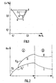
- FIG. 1 represents the diagram of the compositions in the plane Ox, y, where the abscissa Ox represents the weight percentage in Mn of the alloy of Al, and where the ordinate Oy represents the weight percentage in Cu of the alloy Al.
- the polygon ABCD delimits the domain of the Mn and Cu compositions of the aluminum alloys corresponding to the uses according to the invention.
- the polygon EFGH delimits the preferred domain of the Mn and Cu compositions of the aluminum alloys corresponding to the uses according to the invention.
- FIG. 2 is a qualitative illustration of the variation of the mechanical characteristics Rm (on the ordinate), as a function of the height H (on the abscissa) of the aerosol can obtained for the same starting pawn, on the left part A of the diagram, as a function of the heat treatment time for baking varnishes and inks (on the abscissa), on the right-hand side B.
- Curve I corresponds to the impact spinning process
- curve II corresponds to a first step F n of impact spinning, followed by a second stretch step E n .
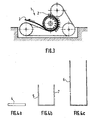
- Figure 3 is a sectional view of a continuous casting device "4R" (1), supplied of liquid metal (2), for the manufacture of strip (3) intended for the manufacture, by stamping, pins (4) before substantially the same thickness as said strip (3).
- FIGS. 4a to 4c are a schematic illustration of the preferred method corresponding to the use according to the invention, comprising the transformation of a starting pawn (4) (FIG. 4a) into a draft spun (5) (FIG. 4b), and the transformation of this blank (5) into an aerosol can (6) by drawing with reduction in thickness of the wall (7) of the blank (5).
- the aluminum alloy corresponding to the use according to the invention has a composition of Cu and Mn which is located inside the polygon EFGH defined by the coordinates of the points EFG and H (% by weight) abscissa (% Mn) ordinate (% Cu) E 0.25 0.6 F 0.45 0.6 G 0.4 0.5 H 0.3 0.5 as shown in figure 1.
- the alloy compositions are particularly advantageous when, on the one hand, the pins (4) are obtained from continuous casting strip (3) as illustrated in FIG. 3, and when, on the other hand, the pins are transformed into aerosol cans by a first step of impact spinning, followed by a second step of drawing, as shown schematically in Figures 4a to 4c.
- Figure 2 illustrates the advantages of this process on the mechanical characteristics (Rm).
- the alloys corresponding to the use according to the invention are less sensitive than the standard alloys or the alloys outside the invention, to the effects of the heat treatment (part B of FIG. 2) and to the reduction of the mechanical characteristics. which results from this treatment.
- the invention makes it possible to obtain aerosol cans having, as desired, either better mechanical characteristics and therefore resistance to higher internal pressure, or a reduced wall thickness which corresponds to a saving in metal.
- the alloy may, in addition to the elements Cu and Mn, comprise other elements: 0.005 to 0.05% by weight of Ti, from 0.2 to 0.5% by weight of Fe, and less than 0.2% by weight of Si.
- the use of titanium is aimed at obtaining relatively fine-grained casting tape (3).
- the elements Fe and Si are most often impurities from aluminum.
- the Fe content results from the fact that this element, at a content greater than 0.2% by weight, plays a role in reducing the size of the grains, while beyond a content of 0.5% in weight, its effect is negative, because it annihilates the effect of manganese by trapping this element.
- Silicon is a simple impurity, the content of which must be kept below 0.2% by weight, otherwise the solubility of manganese will be reduced, which leads in particular to larger grains.
- An object of the invention relates to the use according to the invention of alloys for obtaining aerosol cans produced by shock spinning of pawns (4) of said alloy, said pawns being obtained from continuously cast strip.
- this second object relates to the use according to the invention of the alloys for obtaining aerosol cans produced by shock spinning of pins (4) of said alloy and subsequent drawing of the blank (5) obtained, said pins being obtained from continuous casting tape.
- the selection of alloys is particularly suitable in the case of pawns obtained from continuously cast strip, and more particularly advantageous when these pawns are transformed into aerosol cans by impact spinning followed by a step d 'drawing.
- Another object of the invention is constituted by the aerosol cans obtained by shock spinning of pins (4) of said alloy, said pins being obtained from continuously cast strip.
- this other object consists of aerosol cans obtained by impact shocking of pawns of said alloy followed by at least one drawing step, said pawns being obtained from continuously cast strip.
Landscapes
- Chemical & Material Sciences (AREA)
- Engineering & Computer Science (AREA)
- Materials Engineering (AREA)
- Mechanical Engineering (AREA)
- Metallurgy (AREA)
- Organic Chemistry (AREA)
- Containers And Packaging Bodies Having A Special Means To Remove Contents (AREA)
- Cosmetics (AREA)
- Extrusion Of Metal (AREA)
- Shaping Metal By Deep-Drawing, Or The Like (AREA)
Description
Selon cet état de la technique, les pions sont obtenus à partir de bande par laminage à chaud, puis laminage à froid.
De manière connue en soi, les boítiers filés par choc sont ensuite typiquement dégraissés, vernis intérieurement et/ou imprimés extérieurement, traités dans un four de manière à cuire les encres et sécher les vernis, et finalement conifiés.
| abscisse (Mn%) | ordonnée (Cu %) | |
| A | 0,075 | 0,65 |
| B | 0,50 | 0,65 |
| C | 0,35 | 0,4 |
| D | 0,25 | 0,4 |
Cette composition d'alliage a éte trouvée particulièrement adaptée à la fabrication de pions à partir de bande coulée en continu.
En ce qui concerne les teneurs en Mn, elles visent surtout à diminuer l'adoucissement du métal lors du recuit (les laques et vernis des boítiers aérosols. Les essais conduits par la demanderesse ont montré qu'une teneur en Mn se situant en-deça de la limite imposée par la droite AD conduirait à un pion à grain trop gros, entraínant in fine la formation de plis lors de la conification de l'aérosol final. Par ailleurs, une teneur en Mn se situant en-deça de la limite imposée par la droite AD conduirait en plus à un aérosol de caractéristiques mécaniques insuffisantes compte tenu notamment de la nécessité de diminuer l'épaisseur des parois de boítiers d'aérosols pour diminuer notablement les coûts de métal.
En particulier quand la teneur en Mn est comprise entre 0,2 et 0,4% en poids, il a été observé un fort effet anti-adoucissant du Mn qui entraíne une augmentation très marquée des caractéristiques mécaniques. Cet effet est particulièrement remarquable dans le cas d'alliages contenant aussi du Cu, en effet ces alliages d'aluminium avec Cu s'adoucissent très vite on peut ainsi considérer que l'ajout de 0,3% de Mn à un alliage d'aluminium 1050 (désignation de l'Aluminum Association) fait gagner 15 MPa, alors que le même ajout à un alliage 1050 contenant 0,5% de Cu fait gagner 30 MPa. Ainsi, il a été observé une forte synergie entre les éléments Cu et Mn.
Pour de fortes teneurs en Mn, typiquement supérieures à 0,5%, l'ajout supplémentaire de Mn n'apporte rien car l'alliage ne s'adoucit quasiment plus lors des recuits des laques ou vernis des boítiers d'aérosols, et généralement d'ailleurs, un ajout de Mn au-dessus de 0,5 % en poids ne fait que dégrader la structure du métal.
En ce qui concerne la teneurs en cuivre, les essais ont montré qu'il y avait intérêt, pour obtenir une tenue élevée à la corrosion, à ce que la teneur en Cu soit inférieure à 0,65 % (ordonnée de la droite AB), mais qu'elle soit supérieure à 0,4% (ordonnée de la droite CD) pour obtenir un aérosol final de caractéristiques mécaniques élevées pour pouvoir réduire l'épaisseur des parois de boítiers d'aérosols.
Le polygone ABCD délimite le domaine des compositions en Mn et Cu des alliages d'aluminium correspondant aux utilisations selon l'invention.
Le polygone EFGH délimite le domaine préféré des compositions en Mn et Cu des alliages d'aluminium correspondant aux utilisations selon l'invention.
La courbe I correspond au procédé de filage par choc, alors que la courbe II correspond à une première étape Fn de filage par choc, suivie d'une seconde étape d'étirage En.
| abscisse (%Mn) | ordonnée (%Cu) | |
| E | 0,25 | 0,6 |
| F | 0,45 | 0,6 |
| G | 0,4 | 0,5 |
| H | 0,3 | 0,5 |
Les compositions d'alliage sont particulièrement avantageuses quand, d'une part, les pions (4) sont obtenus à partir de bande coulée en continu (3) comme illustré à la figure 3, et quand, d'autre part, les pions sont transformés en boítiers d'aérosols par une première étape de filage par choc, suivie d'une seconde étape d'étirage, comme schématisé aux figures 4a a 4c.
La figure 2 illustre les avantages de ce procédé sur les caractéristiques mécaniques (Rm). Il est à noter aussi que les alliages correspondant à l'utilisation selon l'invention sont moins sensibles que les alliages standards ou les alliages hors invention, aux effets du traitement thermique (partie B de la figure 2) et à la diminution des caractéristiques mécaniques qui résulte de ce traitement.
Ainsi, l'invention permet d'obtenir des boítiers d'aérosols présentant, au choix, soit de meilleures caractéristiques mécaniques et donc une tenue à la pression interne supérieure, soit une épaisseur de paroi moindre ce qui correspond à une économie de métal.
L'alliage peut, outre les éléments Cu et Mn, comprendre d'autres éléments : 0,005 à 0,05 % en poids de Ti, de 0,2 à 0,5 % en poids de Fe, et moins de 0,2 % en poids de Si.
L'emploi de titane vise à obtenir de la bande (3) de coulée à grains relativement fins.
Quant aux éléments Fe et Si, ce sont le plus souvent des impuretés de l'aluminium. La teneur en Fe résulte du fait que cet élément, à une teneur supérieure à 0,2% en poids, joue un rôle pour faire baisser la taille des grains, alors qu'au-delà d'une teneur de 0,5% en poids, son effet est négatif, car il annihile l'effet du manganèse en piégeant cet élément.
Le silicium est une simple impureté dont la teneur doit être tenue infériéure à 0,2% en poids sous peine de faire baisser la solubilité du manganèse, ce qui conduit notamment à des grains plus gros
De préférence, ce second objet concerne l'utilisation selon l'invention des alliages pour l'obtention de boítiers d'aérosols fabriqués par filage par choc de pions (4) dudit alliage et étirage subséquent de l'ébauche (5) obtenue, lesdits pions étant obtenus à partir de bande coulée en continu.
Comme déjà indiqué, la sélection d'alliages est particulièrement adaptée dans le cas de pions obtenus à partir de bande coulée en continu, et plus particulièrement avantageuse quand ces pions sont transformés en boítiers d'aérosol par filage par choc suivi d'une étape d'étirage.
De préférence, cet autre objet est constitué par des boítiers d'aérosols obtenus par filage par choc de pions dudit alliage suivi d'au moins une étape d'étirage, lesdits pions étant obtenus à partir de bande coulée en continu.
- diamètre : 45 mm
- hauteur : 290 mm
- épaisseur de paroi 0.28 mm
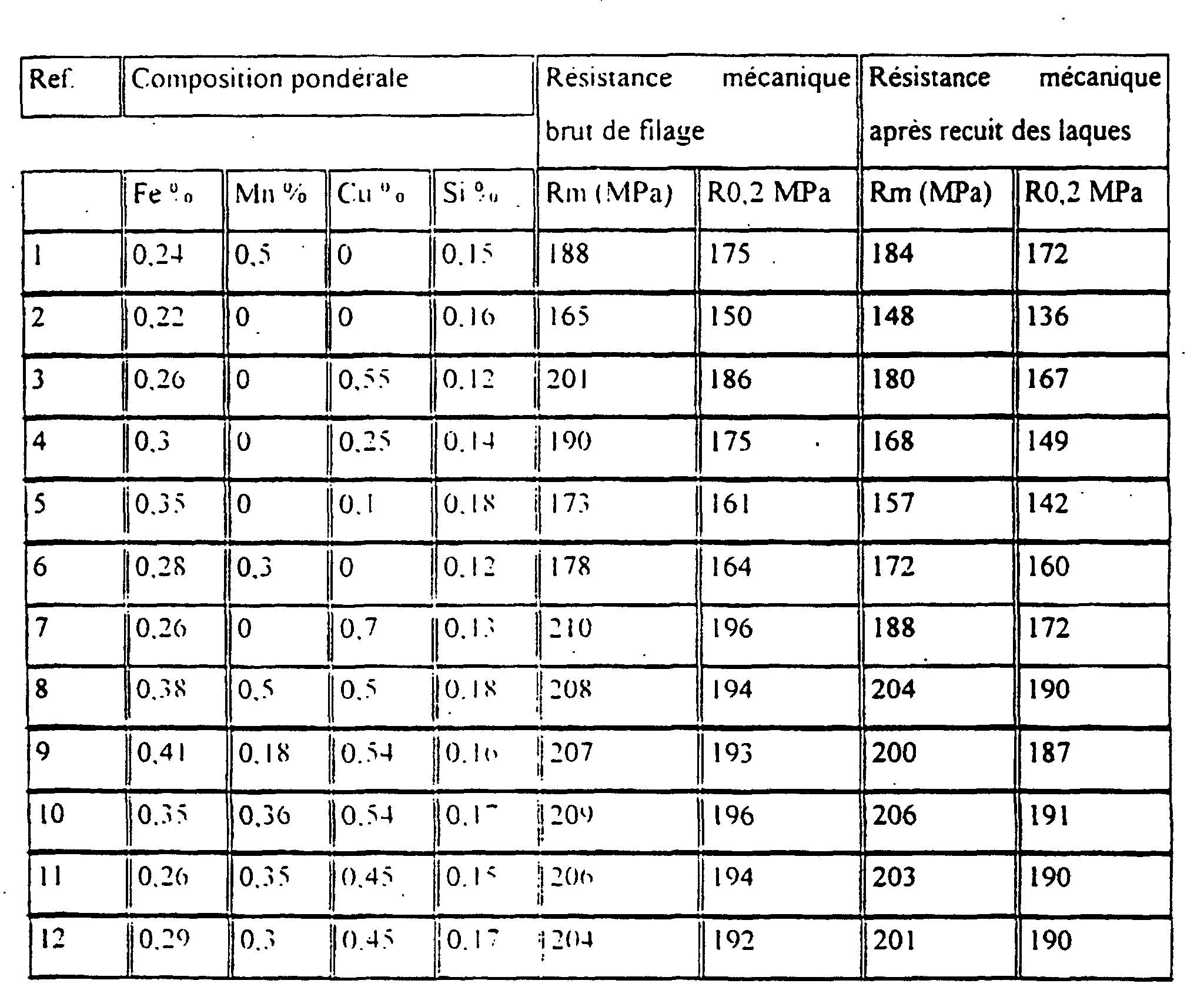
La comparaison des essais 8 et 10 montre bien un plafonnement des caractéristiques mécaniques, une augmentation de la teneur en Mn, au-delà des teneurs correspondant aux compositions en Cu et Mn situées à l'intérieur du polygone ABCD, n'améliore pas les caractéristiques mécaniques.
| Réf. | Résistance à la corrosion | Mise en forme (filage + étirage) | |
| Taille des grains µm | Aptitude à la conification | ||
| 1 | comme Al 1050 | 300 | Plis |
| 2 | Idem | 50 | Pas de plis |
| 3 | Idem | 30 | Pas de plis |
| 4 | Idem | 40 | Pas de plis |
| 5 | idem | 40 | Pas de plis |
| 6 | idem | 220 | Début de plis |
| 7 | Piqûres | 30 | Pas de plis |
| 8 | comme Al 1050 | 300 | Plis |
| 9 | comme Al 1050 | 70 | Pas de plis |
| 10 | comme Al 1050 | 120 | Pas de plis |
| 11 | comme Al 1050 | 135 | Pas de plis |
| 12 | comme Al 1050 | 120 | Pas de plis |
Claims (6)
- Utilisation d'alliages d'aluminium pour la fabrication de boítiers d'aérosols par filage par choc de pions dudit alliage suivi d'un étirage, alliages comprenant du cuivre et du manganèse, et dont la composition consiste en: une teneur en Cu et Mn située à l'intérieur du polygone ABCD défini, dans un système d'axes de coordonnées où la teneur en Mn (% en poids) figure en abscisse et où celle en Cu (% en poids) figure en ordonnée, par les coordonnées des points A, B, C et D:
abscisse ordonnée A 0,075 0,65 B 0,50 0,65 C 0,35 0,4 D 0,25 0,4
le reste étant de l'aluminium et des impuretés inévitables. - Utilisation d'alliages d'aluminium pour la fabrication de boítiers d'aérosols par filage par choc de pions dudit alliage ou par filage par choc suivi d'un étirage, alliages comprenant du cuivre et du manganèse, et dont la composition consiste en: une teneur en Cu et Mn située à l'intérieur du polygone EFGH défini, dans un système d'axes de coordonnées où la teneur en Mn (% en poids) figure en abscisse et où celle en Cu (% en poids) figure en ordonnée, par les coordonnées des points E, F, G et H :
abscisse ordonnée E 0,25 0,6 F 0,45 0,6 G 0,4 0,5 H 0,3 0,5
le reste étant de l'aluminium et des impuretés inévitables. - Utilisation d'alliages selon une quelconque des revendications 1 à 2 pour l'obtention de boítiers d'aérosols par filage par choc de pions desdits alliages, lesdits pions étant obtenus à partir de bande coulée en continu.
- Utilisation d'alliages selon une quelconque des revendications 1 à 2 pour l'obtention de boítiers d'aérosols par filage par choc de pions desdits alliages et étirage subséquent de l'ébauche obtenue, lesdits pions étant obtenus à partir de bande coulée en continu.
- Boítiers d'aérosols en alliages d'aluminium utilisés selon une quelconque des revendications 1 à 4, obtenus par filage par choc de pions constitués desdits alliages, lesdits pions étant obtenus à partir de bande coulée en continu.
- Boítiers d'aérosols en alliages d'aluminium utilisés selon une quelconque des revendications 1 à 4, obtenus par filage par choc de pions constitués desdits alliages, ledit filage étant suivi d'au moins une étape d'étirage, lesdits pions étant obtenus à partir de bande coulée en continu.
Priority Applications (1)
| Application Number | Priority Date | Filing Date | Title |
|---|---|---|---|
| SI9930081T SI1064413T1 (en) | 1998-01-22 | 1999-01-20 | Aluminium alloy for aerosol housing |
Applications Claiming Priority (3)
| Application Number | Priority Date | Filing Date | Title |
|---|---|---|---|
| FR9800869 | 1998-01-22 | ||
| FR9800869A FR2773819B1 (fr) | 1998-01-22 | 1998-01-22 | Alliage d'aluminium pour boitier d'aerosol |
| PCT/FR1999/000106 WO1999037826A1 (fr) | 1998-01-22 | 1999-01-20 | Alliage d'aluminium pour boitier d'aerosol |
Publications (2)
| Publication Number | Publication Date |
|---|---|
| EP1064413A1 EP1064413A1 (fr) | 2001-01-03 |
| EP1064413B1 true EP1064413B1 (fr) | 2002-04-24 |
Family
ID=9522227
Family Applications (1)
| Application Number | Title | Priority Date | Filing Date |
|---|---|---|---|
| EP99900964A Expired - Lifetime EP1064413B1 (fr) | 1998-01-22 | 1999-01-20 | Alliage d'aluminium pour boitier d'aerosol |
Country Status (15)
| Country | Link |
|---|---|
| EP (1) | EP1064413B1 (fr) |
| KR (1) | KR20010024776A (fr) |
| CN (1) | CN1288487A (fr) |
| AR (1) | AR014420A1 (fr) |
| AT (1) | ATE216738T1 (fr) |
| AU (1) | AU2060599A (fr) |
| BR (1) | BR9907215A (fr) |
| CA (1) | CA2318389A1 (fr) |
| CZ (1) | CZ20002512A3 (fr) |
| DE (1) | DE69901341T2 (fr) |
| ES (1) | ES2175929T3 (fr) |
| FR (1) | FR2773819B1 (fr) |
| HU (1) | HUP0100376A3 (fr) |
| PL (1) | PL341380A1 (fr) |
| WO (1) | WO1999037826A1 (fr) |
Cited By (6)
| Publication number | Priority date | Publication date | Assignee | Title |
|---|---|---|---|---|
| US7954354B2 (en) | 2006-06-26 | 2011-06-07 | Alcoa Inc. | Method of manufacturing containers |
| US8322183B2 (en) | 2006-05-16 | 2012-12-04 | Alcoa Inc. | Manufacturing process to produce a necked container |
| US9327338B2 (en) | 2012-12-20 | 2016-05-03 | Alcoa Inc. | Knockout for use while necking a metal container, die system for necking a metal container and method of necking a metal container |
| DE102018215243A1 (de) * | 2018-09-07 | 2020-03-12 | Neumann Aluminium Austria Gmbh | Aluminiumlegierung, Halbzeug, Dose, Verfahren zur Herstellung eines Butzen, Verfahren zur Herstellung einer Dose sowie Verwendung einer Aluminiumlegierung |
| DE102018215254A1 (de) * | 2018-09-07 | 2020-03-12 | Neuman Aluminium Austria Gmbh | Aluminiumlegierung, Halbzeug, Dose, Verfahren zur Herstellung eines Butzen, Verfahren zur Herstellung einer Dose sowie Verwendung einer Aluminiumlegierung |
| DE102020119466A1 (de) | 2020-07-23 | 2022-01-27 | Nussbaum Matzingen Ag | Aluminiumlegierung und Verfahren zur Herstellung einer Aluminiumlegierung |
Families Citing this family (12)
| Publication number | Priority date | Publication date | Assignee | Title |
|---|---|---|---|---|
| AR032233A1 (es) | 2002-01-09 | 2003-10-29 | Maria Eugenia Barrera | Un procedimiento para conformar un envase de alta resistencia, particularmente un envase para aerosoles y a un envase obtenido mediante dicho procedimiento |
| EP3851223B1 (fr) | 2010-08-20 | 2024-09-11 | Kaiser Aluminum Warrick, LLC | Récipient métallique façonné |
| CA2979863C (fr) | 2011-09-16 | 2019-11-12 | Ball Corporation | Contenants files par choc a partir de dechets d'aluminium recycles |
| JP6255084B2 (ja) | 2013-04-09 | 2017-12-27 | ボール コーポレイションBall Corporation | 再利用アルミニウム合金から作られる、ネジ込みネックを有するアルミニウム衝撃押出成形ボトル及びその製法 |
| SI24969A (sl) * | 2015-04-03 | 2016-10-28 | TALUM d.d. KidriÄŤevo | Aluminijeva zlitina za izdelavo aluminijevih aerosol doz s protismernim izstiskovanjem in postopek za njeno izdelavo |
| US20180044155A1 (en) | 2016-08-12 | 2018-02-15 | Ball Corporation | Apparatus and Methods of Capping Metallic Bottles |
| RU2736632C1 (ru) | 2016-12-30 | 2020-11-19 | Болл Корпорейшн | Алюминиевый сплав для контейнеров, получаемых ударным выдавливанием, и способ его получения |
| EP3681654A4 (fr) | 2017-09-15 | 2021-06-09 | Ball Corporation | Système et procédé de formation d'une fermeture métallique pour un récipient fileté |
| EP3940100A1 (fr) | 2020-07-16 | 2022-01-19 | Envases Metalúrgicos De Álava, S.A. | Alliages d'aluminium pour la fabrication de boîtes d'aluminium par extrusion par percussion |
| EP3940099A1 (fr) | 2020-07-16 | 2022-01-19 | Envases Metalúrgicos De Álava, S.A. | Alliages d'aluminium pour la fabrication de boîtes d'aluminium par extrusion par percussion |
| EP3940098A1 (fr) | 2020-07-16 | 2022-01-19 | Envases Metalúrgicos De Álava, S.A. | Alliages d'aluminium pour la fabrication de canettes d'aluminium par extrusion par percussion |
| CA3243709A1 (fr) | 2022-02-04 | 2023-08-10 | Ball Corporation | Procédé de formation d'une boucle et récipient métallique fileté comprenant celle-ci |
Family Cites Families (6)
| Publication number | Priority date | Publication date | Assignee | Title |
|---|---|---|---|---|
| FR2457328A1 (fr) * | 1979-05-25 | 1980-12-19 | Cebal | Alliage d'aluminium de type a-gs |
| JPH01149939A (ja) * | 1987-12-05 | 1989-06-13 | Kobe Steel Ltd | 耐孔蝕性に優れたインパクト加工用アルミニウム合金 |
| WO1991014794A1 (fr) * | 1990-03-27 | 1991-10-03 | Alcan International Limited | Amelioration d'alliage d'aluminium |
| JPH0733559B2 (ja) * | 1990-03-29 | 1995-04-12 | 住友軽金属工業株式会社 | ろう付性及び耐食性の優れたアルミニウム合金ブレージングシートの製造方法 |
| JP3256904B2 (ja) * | 1992-04-03 | 2002-02-18 | 古河電気工業株式会社 | O材タイプの熱交換器用アルミニウム合金押出しチューブ |
| JPH05320798A (ja) * | 1992-05-26 | 1993-12-03 | Furukawa Alum Co Ltd | 熱交換器用アルミニウム合金押し出しチューブ |
-
1998
- 1998-01-22 FR FR9800869A patent/FR2773819B1/fr not_active Expired - Fee Related
-
1999
- 1999-01-18 AR ARP990100183A patent/AR014420A1/es unknown
- 1999-01-20 DE DE69901341T patent/DE69901341T2/de not_active Expired - Fee Related
- 1999-01-20 CZ CZ20002512A patent/CZ20002512A3/cs unknown
- 1999-01-20 CN CN99802118A patent/CN1288487A/zh active Pending
- 1999-01-20 BR BR9907215-7A patent/BR9907215A/pt not_active Application Discontinuation
- 1999-01-20 AU AU20605/99A patent/AU2060599A/en not_active Abandoned
- 1999-01-20 HU HU0100376A patent/HUP0100376A3/hu unknown
- 1999-01-20 ES ES99900964T patent/ES2175929T3/es not_active Expired - Lifetime
- 1999-01-20 WO PCT/FR1999/000106 patent/WO1999037826A1/fr not_active Ceased
- 1999-01-20 AT AT99900964T patent/ATE216738T1/de not_active IP Right Cessation
- 1999-01-20 PL PL99341380A patent/PL341380A1/xx unknown
- 1999-01-20 KR KR1020007006788A patent/KR20010024776A/ko not_active Withdrawn
- 1999-01-20 EP EP99900964A patent/EP1064413B1/fr not_active Expired - Lifetime
- 1999-01-20 CA CA002318389A patent/CA2318389A1/fr not_active Abandoned
Cited By (8)
| Publication number | Priority date | Publication date | Assignee | Title |
|---|---|---|---|---|
| US8322183B2 (en) | 2006-05-16 | 2012-12-04 | Alcoa Inc. | Manufacturing process to produce a necked container |
| US7954354B2 (en) | 2006-06-26 | 2011-06-07 | Alcoa Inc. | Method of manufacturing containers |
| US8555692B2 (en) | 2006-06-26 | 2013-10-15 | Alcoa Inc. | Expanding die and method of shaping containers |
| US9327338B2 (en) | 2012-12-20 | 2016-05-03 | Alcoa Inc. | Knockout for use while necking a metal container, die system for necking a metal container and method of necking a metal container |
| DE102018215243A1 (de) * | 2018-09-07 | 2020-03-12 | Neumann Aluminium Austria Gmbh | Aluminiumlegierung, Halbzeug, Dose, Verfahren zur Herstellung eines Butzen, Verfahren zur Herstellung einer Dose sowie Verwendung einer Aluminiumlegierung |
| DE102018215254A1 (de) * | 2018-09-07 | 2020-03-12 | Neuman Aluminium Austria Gmbh | Aluminiumlegierung, Halbzeug, Dose, Verfahren zur Herstellung eines Butzen, Verfahren zur Herstellung einer Dose sowie Verwendung einer Aluminiumlegierung |
| US12157933B2 (en) | 2018-09-07 | 2024-12-03 | Tubex Holding Gmbh | Aluminium alloy, semi-finished product, can, method of producing a slug, method of producing a can, and use of an aluminium alloy |
| DE102020119466A1 (de) | 2020-07-23 | 2022-01-27 | Nussbaum Matzingen Ag | Aluminiumlegierung und Verfahren zur Herstellung einer Aluminiumlegierung |
Also Published As
| Publication number | Publication date |
|---|---|
| ATE216738T1 (de) | 2002-05-15 |
| ES2175929T3 (es) | 2002-11-16 |
| AU2060599A (en) | 1999-08-09 |
| CA2318389A1 (fr) | 1999-07-29 |
| EP1064413A1 (fr) | 2001-01-03 |
| AR014420A1 (es) | 2001-02-28 |
| CN1288487A (zh) | 2001-03-21 |
| DE69901341D1 (de) | 2002-05-29 |
| WO1999037826A1 (fr) | 1999-07-29 |
| BR9907215A (pt) | 2000-10-24 |
| DE69901341T2 (de) | 2002-11-28 |
| PL341380A1 (en) | 2001-04-09 |
| FR2773819B1 (fr) | 2000-03-10 |
| HUP0100376A3 (en) | 2001-07-30 |
| CZ20002512A3 (cs) | 2001-12-12 |
| KR20010024776A (ko) | 2001-03-26 |
| HUP0100376A2 (hu) | 2001-05-28 |
| FR2773819A1 (fr) | 1999-07-23 |
Similar Documents
| Publication | Publication Date | Title |
|---|---|---|
| EP1064413B1 (fr) | Alliage d'aluminium pour boitier d'aerosol | |
| EP2516687B1 (fr) | Pièce moulée en alliage d'aluminium au cuivre à haute résistance mécanique et au fluage à chaud | |
| EP2997171B1 (fr) | Tôle en alliage d'aluminium pour bouteille métallique ou boîtier d'aérosol | |
| WO2004001079A2 (fr) | Piece moulee en alliage d'aluminium a haute resistance a chaud | |
| CA2851592A1 (fr) | Procede de transformation ameliore de toles en alliage al-cu-li | |
| EP0679199A1 (fr) | Alliage de type aluminium-silicon-magnesium a ductilite et emboutissabilite ameliorees et procede d'obtention | |
| FR2816534A1 (fr) | Procede de fabrication d'une bande plaquee en alliage d'aluminium pour la fabrication d'echangeurs de chaleur brases | |
| CA2144757C (fr) | Procede de fabrication d'une feuille mince apte a la confection d'elements constitutifs de boites | |
| EP0521808B1 (fr) | Procédé de fabrication de tôles minces destinées à l'emboutissage | |
| EP1578548B1 (fr) | Vis en acier a tete creuse | |
| EP0474530B1 (fr) | Procédé d'élaboration de produits à très haute charge à la rupture à partir d'un acier austénitique instable, et produits en résultant | |
| EP0070790B1 (fr) | Méthode de fabrication de corps creux sous pression en alliages d'aluminium | |
| EP0119180B1 (fr) | Alliages à base de zinc à ductilité améliorée | |
| JP2007191760A (ja) | Ppキャップ用アルミニウム合金板およびその製造方法 | |
| EP0896637B1 (fr) | Alliage aluminium-silicium-magnesium pour carrosserie automobile | |
| CH627788A5 (en) | Nickel alloy with a high boron content | |
| FR2557144A1 (fr) | Alliage d'aluminium a proprietes ameliorees | |
| JP2001181772A5 (fr) | ||
| CN113106365B (zh) | 2219铝合金铸锭的退火方法及2219铝合金变形件 | |
| EP1488021B1 (fr) | Procédé de traitement thermique d'une pièce de fonderie en alliage a base d'aluminium et pièce de fonderie | |
| JP2005042195A (ja) | 耐胴切れ性に優れるボトル缶用アルミニウム合金板 | |
| EP0064468B1 (fr) | Procédé de fabrication de feuilles en alliages d'aluminium-fer hypoeutectiques | |
| JPH05270225A (ja) | アルミニウム合金製サスペンションアームの製造方法 | |
| JPH05263175A (ja) | ステイオンタブ用アルミニウム合金板 | |
| JPH0762223B2 (ja) | 深絞りクロ−ジヤ−の製造法 |
Legal Events
| Date | Code | Title | Description |
|---|---|---|---|
| PUAI | Public reference made under article 153(3) epc to a published international application that has entered the european phase |
Free format text: ORIGINAL CODE: 0009012 |
|
| 17P | Request for examination filed |
Effective date: 20000720 |
|
| AK | Designated contracting states |
Kind code of ref document: A1 Designated state(s): AT CH DE ES FI FR GB GR IT LI NL |
|
| AX | Request for extension of the european patent |
Free format text: SI PAYMENT 20000720 |
|
| GRAG | Despatch of communication of intention to grant |
Free format text: ORIGINAL CODE: EPIDOS AGRA |
|
| 17Q | First examination report despatched |
Effective date: 20010522 |
|
| GRAG | Despatch of communication of intention to grant |
Free format text: ORIGINAL CODE: EPIDOS AGRA |
|
| GRAH | Despatch of communication of intention to grant a patent |
Free format text: ORIGINAL CODE: EPIDOS IGRA |
|
| REG | Reference to a national code |
Ref country code: GB Ref legal event code: IF02 |
|
| GRAH | Despatch of communication of intention to grant a patent |
Free format text: ORIGINAL CODE: EPIDOS IGRA |
|
| GRAA | (expected) grant |
Free format text: ORIGINAL CODE: 0009210 |
|
| AK | Designated contracting states |
Kind code of ref document: B1 Designated state(s): AT CH DE ES FI FR GB GR IT LI NL |
|
| AX | Request for extension of the european patent |
Free format text: SI PAYMENT 20000720 |
|
| PG25 | Lapsed in a contracting state [announced via postgrant information from national office to epo] |
Ref country code: GR Free format text: LAPSE BECAUSE OF FAILURE TO SUBMIT A TRANSLATION OF THE DESCRIPTION OR TO PAY THE FEE WITHIN THE PRESCRIBED TIME-LIMIT Effective date: 20020424 Ref country code: FI Free format text: LAPSE BECAUSE OF FAILURE TO SUBMIT A TRANSLATION OF THE DESCRIPTION OR TO PAY THE FEE WITHIN THE PRESCRIBED TIME-LIMIT Effective date: 20020424 Ref country code: AT Free format text: LAPSE BECAUSE OF FAILURE TO SUBMIT A TRANSLATION OF THE DESCRIPTION OR TO PAY THE FEE WITHIN THE PRESCRIBED TIME-LIMIT Effective date: 20020424 |
|
| REF | Corresponds to: |
Ref document number: 216738 Country of ref document: AT Date of ref document: 20020515 Kind code of ref document: T |
|
| REG | Reference to a national code |
Ref country code: GB Ref legal event code: FG4D Free format text: NOT ENGLISH |
|
| REG | Reference to a national code |
Ref country code: CH Ref legal event code: EP |
|
| REF | Corresponds to: |
Ref document number: 69901341 Country of ref document: DE Date of ref document: 20020529 |
|
| GBT | Gb: translation of ep patent filed (gb section 77(6)(a)/1977) |
Effective date: 20020718 |
|
| REG | Reference to a national code |
Ref country code: ES Ref legal event code: FG2A Ref document number: 2175929 Country of ref document: ES Kind code of ref document: T3 |
|
| PG25 | Lapsed in a contracting state [announced via postgrant information from national office to epo] |
Ref country code: GB Free format text: LAPSE BECAUSE OF NON-PAYMENT OF DUE FEES Effective date: 20030120 |
|
| PG25 | Lapsed in a contracting state [announced via postgrant information from national office to epo] |
Ref country code: ES Free format text: LAPSE BECAUSE OF NON-PAYMENT OF DUE FEES Effective date: 20030121 |
|
| PG25 | Lapsed in a contracting state [announced via postgrant information from national office to epo] |
Ref country code: LI Free format text: LAPSE BECAUSE OF NON-PAYMENT OF DUE FEES Effective date: 20030131 Ref country code: CH Free format text: LAPSE BECAUSE OF NON-PAYMENT OF DUE FEES Effective date: 20030131 |
|
| PLBE | No opposition filed within time limit |
Free format text: ORIGINAL CODE: 0009261 |
|
| STAA | Information on the status of an ep patent application or granted ep patent |
Free format text: STATUS: NO OPPOSITION FILED WITHIN TIME LIMIT |
|
| 26N | No opposition filed |
Effective date: 20030127 |
|
| GBPC | Gb: european patent ceased through non-payment of renewal fee | ||
| REG | Reference to a national code |
Ref country code: CH Ref legal event code: PL |
|
| REG | Reference to a national code |
Ref country code: FR Ref legal event code: CJ Ref country code: FR Ref legal event code: CD Ref country code: FR Ref legal event code: CA |
|
| REG | Reference to a national code |
Ref country code: ES Ref legal event code: FD2A Effective date: 20030121 |
|
| REG | Reference to a national code |
Ref country code: FR Ref legal event code: TP |
|
| REG | Reference to a national code |
Ref country code: SI Ref legal event code: IF |
|
| PG25 | Lapsed in a contracting state [announced via postgrant information from national office to epo] |
Ref country code: IT Free format text: LAPSE BECAUSE OF NON-PAYMENT OF DUE FEES;WARNING: LAPSES OF ITALIAN PATENTS WITH EFFECTIVE DATE BEFORE 2007 MAY HAVE OCCURRED AT ANY TIME BEFORE 2007. THE CORRECT EFFECTIVE DATE MAY BE DIFFERENT FROM THE ONE RECORDED. Effective date: 20050120 |
|
| NLT1 | Nl: modifications of names registered in virtue of documents presented to the patent office pursuant to art. 16 a, paragraph 1 |
Owner name: CEBAL S.A.S. |
|
| REG | Reference to a national code |
Ref country code: SI Ref legal event code: SP73 Owner name: CEBAL AEROSOL FRANCE; FR Effective date: 20050509 |
|
| PGFP | Annual fee paid to national office [announced via postgrant information from national office to epo] |
Ref country code: NL Payment date: 20070131 Year of fee payment: 9 |
|
| PGFP | Annual fee paid to national office [announced via postgrant information from national office to epo] |
Ref country code: DE Payment date: 20070209 Year of fee payment: 9 |
|
| PGFP | Annual fee paid to national office [announced via postgrant information from national office to epo] |
Ref country code: FR Payment date: 20070130 Year of fee payment: 9 |
|
| NLV4 | Nl: lapsed or anulled due to non-payment of the annual fee |
Effective date: 20080801 |
|
| PG25 | Lapsed in a contracting state [announced via postgrant information from national office to epo] |
Ref country code: NL Free format text: LAPSE BECAUSE OF NON-PAYMENT OF DUE FEES Effective date: 20080801 Ref country code: DE Free format text: LAPSE BECAUSE OF NON-PAYMENT OF DUE FEES Effective date: 20080801 |
|
| REG | Reference to a national code |
Ref country code: SI Ref legal event code: KO00 Effective date: 20080822 |
|
| REG | Reference to a national code |
Ref country code: FR Ref legal event code: ST Effective date: 20081029 |
|
| PG25 | Lapsed in a contracting state [announced via postgrant information from national office to epo] |
Ref country code: FR Free format text: LAPSE BECAUSE OF NON-PAYMENT OF DUE FEES Effective date: 20080131 |
|
| PGFP | Annual fee paid to national office [announced via postgrant information from national office to epo] |
Ref country code: IT Payment date: 20071130 Year of fee payment: 9 |
|
| PGRI | Patent reinstated in contracting state [announced from national office to epo] |
Ref country code: IT Effective date: 20091201 |
|
| PGRI | Patent reinstated in contracting state [announced from national office to epo] |
Ref country code: IT Effective date: 20091201 |