EP1063042A1 - Schneidvorrichtung für Bleche - Google Patents
Schneidvorrichtung für Bleche Download PDFInfo
- Publication number
- EP1063042A1 EP1063042A1 EP00113232A EP00113232A EP1063042A1 EP 1063042 A1 EP1063042 A1 EP 1063042A1 EP 00113232 A EP00113232 A EP 00113232A EP 00113232 A EP00113232 A EP 00113232A EP 1063042 A1 EP1063042 A1 EP 1063042A1
- Authority
- EP
- European Patent Office
- Prior art keywords
- plate
- knife
- column
- cutting
- guide
- Prior art date
- Legal status (The legal status is an assumption and is not a legal conclusion. Google has not performed a legal analysis and makes no representation as to the accuracy of the status listed.)
- Granted
Links
- 238000005520 cutting process Methods 0.000 title claims description 33
- 239000002184 metal Substances 0.000 title claims description 10
- 238000005096 rolling process Methods 0.000 claims description 5
- 239000000463 material Substances 0.000 description 2
- 238000000034 method Methods 0.000 description 2
- 238000003860 storage Methods 0.000 description 2
- 230000009286 beneficial effect Effects 0.000 description 1
- 238000010276 construction Methods 0.000 description 1
- 230000003292 diminished effect Effects 0.000 description 1
- 238000006073 displacement reaction Methods 0.000 description 1
- 230000000694 effects Effects 0.000 description 1
- 238000004519 manufacturing process Methods 0.000 description 1
- 238000005555 metalworking Methods 0.000 description 1
- 239000002699 waste material Substances 0.000 description 1
Images

Classifications
-
- B—PERFORMING OPERATIONS; TRANSPORTING
- B23—MACHINE TOOLS; METAL-WORKING NOT OTHERWISE PROVIDED FOR
- B23D—PLANING; SLOTTING; SHEARING; BROACHING; SAWING; FILING; SCRAPING; LIKE OPERATIONS FOR WORKING METAL BY REMOVING MATERIAL, NOT OTHERWISE PROVIDED FOR
- B23D15/00—Shearing machines or shearing devices cutting by blades which move parallel to themselves
- B23D15/06—Sheet shears
Definitions
- the invention relates to a cutting device for sheets with at least one firmly arranged on a knife structure of a base Lower knife and at least one in a column guide of a head plate vertically movable upper knife.
- Cutting devices of the generic type described above are generally known, for example from DE 34 31 111 C2, in which one Plate shears for cutting sheet metal strips is disclosed, and DE 42 31 479 A1, in which a shear device is described, and in all Areas of metalworking and manufacturing used everywhere, where sheet metal plates are to be broken down into smaller units.
- the column guides the movable head plates of such cutting devices ensure within certain tolerances that the movable Upper knife precisely for the lower part of the tool or a cutting die is led.
- the object of the present invention is therefore a cutting device of the generic type so that the increased Requirements regarding cutting quality, speed and tolerances enough.
- This construction according to the invention ensures that Upper knife independent of the column guide of the head plate separately is guided, resulting in the cut edges of the sheet metal to be processed especially small cutting gaps and precise fit tolerances as well as a larger cutting zone.
- the harmful Influence of shear forces within the tool diminished as they do for example through the guide play on the press ram and relocations can occur due to the springing of the press frame.
- the floating plate is fixed to the head plate with holding elements, which allow her a movement of approx. 0.1 to 0.2 mm horizontal play.
- the exact guidance of the floating plate and the attached upper knife is through the separate guideways in which the floating plate can perform an upward and downward movement.
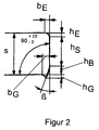
- FIG. 2 shows the cut edge of a workpiece enlarged with then registered characteristic reference values.
- the cutting device shown in the figure has an anchored to the floor Underframe 1 on which a knife assembly 8 is arranged which in turn has a lower knife 10 is fixed.
- the entire cutter is designed as a column structure, with in the outer areas the cutting device two column guides are arranged, one vertical up and down movement of one on the upper, facing away from the base 1 Allow end plate 2 arranged at the end of the column guides.
- the column guides essentially consist of a column block 3, in which a guide column 4 is fixed.
- the guide column 4 is in her upper end facing the head plate 2 in a guide bushing 6 recorded in a receiving block 5 on the head plate 2 is arranged.
- a floating plate 23 on the underside of the head plate 2, which is fixed to the head plate 2 with several holding elements 17 such that there is a slight horizontal mobility in the range from 01 to 0 between the floating plate 23 and the head plate 2 , 2 mm results.
- the floating plate 23 itself is received in two guideways 12 which allow the floating plate to move up and down vertically.
- a knife assembly 21 is fixed, which has a holder for an upper knife 19. The sheet metal plates to be processed are cut by a downward movement of the upper knife 19, the sheet metal plate being held on the cutting table of the cutting device by a hold-down device 16.
- the hold-down device 16 is resiliently supported on the head plate 2 and presses the plate to be cut against the lower knife during the cutting process in order to prevent deformation or displacement of the sheet metal plate. At the same time, the holding-down device (s) hold down the workpiece or waste from the cutting punch after the cutting process.
- the separate guideways 12, 15 of the floating floating plate decouple the upper knife from the column guide between the top plate 2 and the base frame 1.
- the guideways 12 and 15 each consist of a column block 11, in which a guide column 12 is fixed, the column block 11 in turn is set to Subordinate. This structure corresponds essentially to the column guide from the top plate 2 to the base 1 already discussed above.
- the upper end of the guide column 12 is guided by a rolling element guide bush 14, which in turn is received in a receiving block 13 on the floating plate 23.
- the extremely small tolerances of the rolling element guide bushings used ensure that the upper knife 19 is guided very precisely, which results in very small cutting gaps and dimensionally accurate fitting tolerances as well as a larger cutting zone for the entire cutting device. In addition, the quality of the cut edge of a workpiece to be machined is improved.
- a single cutting process essentially follows the following described procedure.
- the head plate 2 with the arranged thereon Floating plate 23 is initially in its upper starting position, so that a strip of material can be fed.
- the upper knife 19 and the or Hold-down devices 16 move in the direction of the lower knife 10 first the column guides of the base frame 1 into the guide bushings 6 immerse the head plate 2 and thus a pre-centering of the Effect head part 2 arranged floating plate 23 with the upper knife 19.
- the further downward movement of the head plate 2 then leads to the fact that the guide columns 12 and 15 in the respective assigned rolling element guide bushings Immerse 14 on the floating plate 23 and the final cause precise guidance of the floating plate 23.
- the workpiece itself is at this stage by the hold-down device against the lower knife pressed, so that a further downward movement of the floating plate Cutting process caused by the upper knife 19. Then there is a Stripping the material and ejecting the trimmed workpiece out of the cutter while the head plate 2 is back in its upper starting position to prepare for the next cutting process brought.
Landscapes
- Engineering & Computer Science (AREA)
- Mechanical Engineering (AREA)
- Shearing Machines (AREA)
- Perforating, Stamping-Out Or Severing By Means Other Than Cutting (AREA)
- Control And Other Processes For Unpacking Of Materials (AREA)
- Details Of Cutting Devices (AREA)
- Formation And Processing Of Food Products (AREA)
Abstract
Description
| - Schnittgradhöhe: | hG < 0,1 x s | für s = 0,5 - 1,0 mm |
| hG < 0,05 x s | für s = 1,1 - 3,0 mm | |
| - Bruchflächenwinkel: | β < 3° | für s = 0,5 - 3,0 mm |
| - Kanteneinzugshöhe: | hE < 0,1 x s | für s = 0,5 - 1,0 mm |
| hE < 0,2 x s | für s = 1,1 - 3,0 mm | |
| - Glattschnittfläche: | hS > ¾ x s | |
| - Schnittgeradheit: | SG < 0,03 mm für s = 0,5-1,0 mm auf 1 m Schnittkantenlänge bezogen | |
| SG < 0,04 mm für s = 1,1-3,0 mm auf 1 m Schnittkantenlänge bezogen |
- 1.
- Untergestell
- 2.
- Kopfplatte
- 3.
- Säulenblock
- 4.
- Führungssäule
- 5.
- Aufnahmeblock
- 6.
- Führungsbuchse
- 8.
- Messeraufbau
- 10.
- Untermesser
- 11.
- Säulenblock
- 12.
- Führungssäule
- 13.
- Aufnahmeblock
- 14.
- Wälzkörper-Führungsbuchse
- 15.
- Führungssäule
- 16.
- Niederhalter
- 17.
- Halteelement
- 19.
- Obermesser
- 21.
- Messeraufbau
- 23.
- Schwebeplatte
Claims (3)
- Schneidvorrichtung für Bleche, mit mindestens einem fest an einem Messeraufbau eines Untergestells angeordneten Untermesser und mindestens einem in einer Säulenführung einer Kopfplatte vertikal verfahrbaren Obermesser, dadurch gekennzeichnet, dass das Obermesser (19) an einer an der Kopfplatte (2) schwimmend gelagerten separaten Schwebeplatte (23) festgelegt ist, wobei die Schwebeplatte (23) in mindestens zwei Führungsbahnen (12, 15) vertikal verschieblich aufgenommen ist.
- Schneidvorrichtung nach Anspruch 1, dadurch gekennzeichnet, dass die Führungsbahnen (12, 15) als runde Säulenführungen gestaltet sind, wobei die Säulenführungen in Wälzkörper-Führungsbuchsen (14) vertikal verschieblich gelagert sind.
- Schneidvorrichtung nach Anspruch 1 oder 2, dadurch gekennzeichnet, dass das Obermesser (19) in einem Messerhalter (8) an der Schwebeplatte (23) auswechselbar festgelegt ist.
Applications Claiming Priority (2)
| Application Number | Priority Date | Filing Date | Title |
|---|---|---|---|
| DE19928841 | 1999-06-24 | ||
| DE19928841A DE19928841C1 (de) | 1999-06-24 | 1999-06-24 | Schneidvorrichtung für Bleche |
Publications (2)
| Publication Number | Publication Date |
|---|---|
| EP1063042A1 true EP1063042A1 (de) | 2000-12-27 |
| EP1063042B1 EP1063042B1 (de) | 2005-04-20 |
Family
ID=7912311
Family Applications (1)
| Application Number | Title | Priority Date | Filing Date |
|---|---|---|---|
| EP00113232A Expired - Lifetime EP1063042B1 (de) | 1999-06-24 | 2000-06-21 | Schneidvorrichtung für Bleche |
Country Status (5)
| Country | Link |
|---|---|
| EP (1) | EP1063042B1 (de) |
| AT (1) | ATE293509T1 (de) |
| DE (2) | DE19928841C1 (de) |
| ES (1) | ES2238223T3 (de) |
| PT (1) | PT1063042E (de) |
Cited By (4)
| Publication number | Priority date | Publication date | Assignee | Title |
|---|---|---|---|---|
| CN104416071A (zh) * | 2013-09-05 | 2015-03-18 | 北汽福田汽车股份有限公司 | 用于汽车全景天窗顶盖的修翻模具 |
| CN107414163A (zh) * | 2017-08-01 | 2017-12-01 | 浙江弘道科技有限公司 | 一种金属薄板切割装置 |
| CN112692348A (zh) * | 2020-12-25 | 2021-04-23 | 浙江银安人防设备有限公司 | 一种剪板机以及应用该剪板机的防爆波活门生产工艺 |
| CN119973214A (zh) * | 2025-03-31 | 2025-05-13 | 航天科工火箭技术有限公司 | 一种异形金属管切割装置及使用方法 |
Families Citing this family (6)
| Publication number | Priority date | Publication date | Assignee | Title |
|---|---|---|---|---|
| DE10217026C1 (de) * | 2002-04-12 | 2003-12-04 | Fraunhofer Ges Forschung | Schneideinrichtung |
| DE10359488A1 (de) * | 2003-12-18 | 2005-07-14 | Bayerische Motoren Werke Ag | Schnittwerkzeug |
| DE102004017019A1 (de) * | 2004-04-02 | 2005-10-20 | Volkswagen Ag | Verfahren und Vorrichtung zum Schneiden eines Bleches |
| CN102847775B (zh) * | 2012-08-21 | 2016-05-18 | 无锡美业机械制造有限公司 | 一种剪板模 |
| CN105945167A (zh) * | 2016-06-20 | 2016-09-21 | 天津理工大学 | 一种用于级进模的精确送料导料板装置 |
| CN109500444A (zh) * | 2018-11-18 | 2019-03-22 | 湖南新融创科技有限公司 | 一种手机电池加工用切片机 |
Citations (2)
| Publication number | Priority date | Publication date | Assignee | Title |
|---|---|---|---|---|
| US2846278A (en) * | 1955-11-08 | 1958-08-05 | Lempco Products Inc | Positioning means for guide assemblies of punch press die sets |
| US5490317A (en) * | 1994-06-16 | 1996-02-13 | Microtek Industries, Inc. | Tapered alignment guide arrangement for self aligning part excision die members in tape automated bonding apparatus |
Family Cites Families (5)
| Publication number | Priority date | Publication date | Assignee | Title |
|---|---|---|---|---|
| DE41753C (de) * | J. MÜLLER in Remscheid - Hasten | Parallelscheere | ||
| DE2814190A1 (de) * | 1978-04-03 | 1979-10-04 | Wilhelm Schneider | Tisch- und messerbalkenkonstruktion zum verwindungsfreien schneiden an tafelscheren |
| DE3431111A1 (de) * | 1984-08-24 | 1986-03-06 | Steiner, Richard, 5901 Wilnsdorf | Tafelschere |
| DE3909925A1 (de) * | 1989-03-25 | 1990-09-27 | Oxytechnik Ges Systemtech | Bandschweissanlage |
| US5237901A (en) * | 1992-04-06 | 1993-08-24 | Rohrer Special Machinery Inc. | Shear |
-
1999
- 1999-06-24 DE DE19928841A patent/DE19928841C1/de not_active Expired - Fee Related
-
2000
- 2000-06-21 PT PT00113232T patent/PT1063042E/pt unknown
- 2000-06-21 AT AT00113232T patent/ATE293509T1/de not_active IP Right Cessation
- 2000-06-21 DE DE50010080T patent/DE50010080D1/de not_active Expired - Fee Related
- 2000-06-21 ES ES00113232T patent/ES2238223T3/es not_active Expired - Lifetime
- 2000-06-21 EP EP00113232A patent/EP1063042B1/de not_active Expired - Lifetime
Patent Citations (2)
| Publication number | Priority date | Publication date | Assignee | Title |
|---|---|---|---|---|
| US2846278A (en) * | 1955-11-08 | 1958-08-05 | Lempco Products Inc | Positioning means for guide assemblies of punch press die sets |
| US5490317A (en) * | 1994-06-16 | 1996-02-13 | Microtek Industries, Inc. | Tapered alignment guide arrangement for self aligning part excision die members in tape automated bonding apparatus |
Cited By (5)
| Publication number | Priority date | Publication date | Assignee | Title |
|---|---|---|---|---|
| CN104416071A (zh) * | 2013-09-05 | 2015-03-18 | 北汽福田汽车股份有限公司 | 用于汽车全景天窗顶盖的修翻模具 |
| CN104416071B (zh) * | 2013-09-05 | 2016-08-24 | 北汽福田汽车股份有限公司 | 用于汽车全景天窗顶盖的修翻模具 |
| CN107414163A (zh) * | 2017-08-01 | 2017-12-01 | 浙江弘道科技有限公司 | 一种金属薄板切割装置 |
| CN112692348A (zh) * | 2020-12-25 | 2021-04-23 | 浙江银安人防设备有限公司 | 一种剪板机以及应用该剪板机的防爆波活门生产工艺 |
| CN119973214A (zh) * | 2025-03-31 | 2025-05-13 | 航天科工火箭技术有限公司 | 一种异形金属管切割装置及使用方法 |
Also Published As
| Publication number | Publication date |
|---|---|
| EP1063042B1 (de) | 2005-04-20 |
| DE19928841C1 (de) | 2001-01-18 |
| ES2238223T3 (es) | 2005-09-01 |
| HK1036241A1 (en) | 2001-12-28 |
| PT1063042E (pt) | 2005-09-30 |
| ATE293509T1 (de) | 2005-05-15 |
| DE50010080D1 (de) | 2005-05-25 |
Similar Documents
| Publication | Publication Date | Title |
|---|---|---|
| EP2008736B1 (de) | Werkzeugmaschine und Verfahren zum Ausschleusen eines Werkstückteils | |
| DE19928841C1 (de) | Schneidvorrichtung für Bleche | |
| DE69128660T2 (de) | Einrichtung zum Sortieren von kleinen, aus Blechen gestanzten Werkstücken | |
| DE69508314T2 (de) | Bewegliches Oberwerkzeug zur Trennung der Schnittschablonen von einem Bogen, der durch eine Presse zur Herstellung von Verpackungsmaterial bearbeitet ist | |
| EP0438736B1 (de) | Vorrichtung zum Schneiden von gestapeltem, blattförmigem Gut mit einem Frontaufstosser zum Ausrichten des Gutes an einer Vorschubeinheit | |
| EP1205268B1 (de) | Werkzeugmaschine mit Vorschubeinrichtung | |
| EP0557866B1 (de) | Schere zum Trennen von Schrott | |
| DE4320397C2 (de) | Einrichtung zum Beschicken von Werkzeugmaschinen | |
| CH655041A5 (de) | Schneidpresse zur bearbeitung plattenfoermiger bauteile. | |
| EP0270493A2 (de) | Winkelschere | |
| EP0074041B1 (de) | Schneidpresse zur Bearbeitung von tafelförmigen Werkstücken | |
| DE3149621A1 (de) | Stanzvorrichtung | |
| DE3526950C1 (de) | Fräseinrichtung zum Bearbeiten der Kanten von Blechplatten oder Blechbändern | |
| EP1731256A1 (de) | Laser-Bearbeitungstisch mit bewegbaren Werkstückauflagen | |
| DE3544899A1 (de) | Stuetzvorrichtung fuer abzutrennende streifen bei scher- bzw. schneidmaschinen | |
| EP1402968A1 (de) | Boerdelvorrichtung | |
| DE102016119464B4 (de) | Werkzeug und Werkzeugmaschine sowie Verfahren zur Bearbeitung von plattenförmigen Werkstücken | |
| AT528213B1 (de) | Plattensäge zum Trennen von Werkstücken in mehrere Abschnitte | |
| DE102023111540B3 (de) | Spindel-Pendel-Presse | |
| DE9115347U1 (de) | Vertikale Stanzvorrichtung | |
| EP2726227B1 (de) | Biegepresse mit einer falzvorrichtung und verfahren zur durchführung einer falzung | |
| DE3025552A1 (de) | Lochstanzvorrichtung in betriebsmitteln | |
| DE19617704C2 (de) | Einrichtung zur Verarbeitung von Blechtafeln an geneigt ausgebildeten C- Gestellpressen | |
| EP4735191A1 (de) | Handlingsvorrichtung und verfahren zur entnahme von einem restgitter-teileverbund | |
| DE10226473B4 (de) | Pressenwerkzeug |
Legal Events
| Date | Code | Title | Description |
|---|---|---|---|
| PUAI | Public reference made under article 153(3) epc to a published international application that has entered the european phase |
Free format text: ORIGINAL CODE: 0009012 |
|
| AK | Designated contracting states |
Kind code of ref document: A1 Designated state(s): AT BE CH CY DE DK ES FI FR GB GR IE IT LI LU MC NL PT SE |
|
| AX | Request for extension of the european patent |
Free format text: AL;LT;LV;MK;RO;SI |
|
| 17P | Request for examination filed |
Effective date: 20010601 |
|
| AKX | Designation fees paid |
Free format text: AT BE CH CY DE DK ES FI FR GB GR IE IT LI LU MC NL PT SE |
|
| AXX | Extension fees paid |
Free format text: LT PAYMENT 20010601;LV PAYMENT 20010601 |
|
| 17Q | First examination report despatched |
Effective date: 20040329 |
|
| GRAP | Despatch of communication of intention to grant a patent |
Free format text: ORIGINAL CODE: EPIDOSNIGR1 |
|
| GRAS | Grant fee paid |
Free format text: ORIGINAL CODE: EPIDOSNIGR3 |
|
| GRAA | (expected) grant |
Free format text: ORIGINAL CODE: 0009210 |
|
| AK | Designated contracting states |
Kind code of ref document: B1 Designated state(s): AT BE CH CY DE DK ES FI FR GB GR IE IT LI LU MC NL PT SE |
|
| AX | Request for extension of the european patent |
Extension state: LT LV |
|
| PG25 | Lapsed in a contracting state [announced via postgrant information from national office to epo] |
Ref country code: NL Free format text: LAPSE BECAUSE OF FAILURE TO SUBMIT A TRANSLATION OF THE DESCRIPTION OR TO PAY THE FEE WITHIN THE PRESCRIBED TIME-LIMIT Effective date: 20050420 Ref country code: IE Free format text: LAPSE BECAUSE OF FAILURE TO SUBMIT A TRANSLATION OF THE DESCRIPTION OR TO PAY THE FEE WITHIN THE PRESCRIBED TIME-LIMIT Effective date: 20050420 |
|
| REG | Reference to a national code |
Ref country code: GB Ref legal event code: FG4D Free format text: NOT ENGLISH |
|
| REG | Reference to a national code |
Ref country code: CH Ref legal event code: EP Ref country code: CH Ref legal event code: NV Representative=s name: KATZAROV S.A. |
|
| GBT | Gb: translation of ep patent filed (gb section 77(6)(a)/1977) |
Effective date: 20050420 |
|
| REG | Reference to a national code |
Ref country code: IE Ref legal event code: FG4D Free format text: LANGUAGE OF EP DOCUMENT: GERMAN |
|
| REF | Corresponds to: |
Ref document number: 50010080 Country of ref document: DE Date of ref document: 20050525 Kind code of ref document: P |
|
| PG25 | Lapsed in a contracting state [announced via postgrant information from national office to epo] |
Ref country code: LU Free format text: LAPSE BECAUSE OF NON-PAYMENT OF DUE FEES Effective date: 20050621 Ref country code: CY Free format text: LAPSE BECAUSE OF FAILURE TO SUBMIT A TRANSLATION OF THE DESCRIPTION OR TO PAY THE FEE WITHIN THE PRESCRIBED TIME-LIMIT Effective date: 20050621 |
|
| PG25 | Lapsed in a contracting state [announced via postgrant information from national office to epo] |
Ref country code: MC Free format text: LAPSE BECAUSE OF NON-PAYMENT OF DUE FEES Effective date: 20050630 |
|
| PG25 | Lapsed in a contracting state [announced via postgrant information from national office to epo] |
Ref country code: GR Free format text: LAPSE BECAUSE OF FAILURE TO SUBMIT A TRANSLATION OF THE DESCRIPTION OR TO PAY THE FEE WITHIN THE PRESCRIBED TIME-LIMIT Effective date: 20050720 Ref country code: DK Free format text: LAPSE BECAUSE OF FAILURE TO SUBMIT A TRANSLATION OF THE DESCRIPTION OR TO PAY THE FEE WITHIN THE PRESCRIBED TIME-LIMIT Effective date: 20050720 |
|
| REG | Reference to a national code |
Ref country code: SE Ref legal event code: TRGR |
|
| REG | Reference to a national code |
Ref country code: ES Ref legal event code: FG2A Ref document number: 2238223 Country of ref document: ES Kind code of ref document: T3 |
|
| LTIE | Lt: invalidation of european patent or patent extension |
Effective date: 20050420 |
|
| REG | Reference to a national code |
Ref country code: PT Ref legal event code: SC4A Effective date: 20050713 |
|
| NLV1 | Nl: lapsed or annulled due to failure to fulfill the requirements of art. 29p and 29m of the patents act | ||
| REG | Reference to a national code |
Ref country code: IE Ref legal event code: FD4D |
|
| REG | Reference to a national code |
Ref country code: HK Ref legal event code: GR Ref document number: 1036241 Country of ref document: HK |
|
| ET | Fr: translation filed | ||
| PLBE | No opposition filed within time limit |
Free format text: ORIGINAL CODE: 0009261 |
|
| STAA | Information on the status of an ep patent application or granted ep patent |
Free format text: STATUS: NO OPPOSITION FILED WITHIN TIME LIMIT |
|
| 26N | No opposition filed |
Effective date: 20060123 |
|
| PGFP | Annual fee paid to national office [announced via postgrant information from national office to epo] |
Ref country code: FI Payment date: 20060605 Year of fee payment: 7 |
|
| PGFP | Annual fee paid to national office [announced via postgrant information from national office to epo] |
Ref country code: CH Payment date: 20060719 Year of fee payment: 7 |
|
| PG25 | Lapsed in a contracting state [announced via postgrant information from national office to epo] |
Ref country code: FI Free format text: LAPSE BECAUSE OF NON-PAYMENT OF DUE FEES Effective date: 20070621 |
|
| REG | Reference to a national code |
Ref country code: CH Ref legal event code: PL |
|
| PG25 | Lapsed in a contracting state [announced via postgrant information from national office to epo] |
Ref country code: LI Free format text: LAPSE BECAUSE OF NON-PAYMENT OF DUE FEES Effective date: 20070630 Ref country code: CH Free format text: LAPSE BECAUSE OF NON-PAYMENT OF DUE FEES Effective date: 20070630 |
|
| PGFP | Annual fee paid to national office [announced via postgrant information from national office to epo] |
Ref country code: ES Payment date: 20080411 Year of fee payment: 9 |
|
| PGFP | Annual fee paid to national office [announced via postgrant information from national office to epo] |
Ref country code: AT Payment date: 20080617 Year of fee payment: 9 |
|
| PGFP | Annual fee paid to national office [announced via postgrant information from national office to epo] |
Ref country code: IT Payment date: 20080626 Year of fee payment: 9 Ref country code: PT Payment date: 20080609 Year of fee payment: 9 Ref country code: BE Payment date: 20080416 Year of fee payment: 9 |
|
| PGFP | Annual fee paid to national office [announced via postgrant information from national office to epo] |
Ref country code: DE Payment date: 20080611 Year of fee payment: 9 Ref country code: SE Payment date: 20080609 Year of fee payment: 9 |
|
| PGFP | Annual fee paid to national office [announced via postgrant information from national office to epo] |
Ref country code: FR Payment date: 20080328 Year of fee payment: 9 |
|
| PGFP | Annual fee paid to national office [announced via postgrant information from national office to epo] |
Ref country code: GB Payment date: 20080609 Year of fee payment: 9 |
|
| BERE | Be: lapsed |
Owner name: HEINZ *SCHWARZ G.M.B.H. & CO. K.G. Effective date: 20090630 |
|
| REG | Reference to a national code |
Ref country code: PT Ref legal event code: MM4A Free format text: LAPSE DUE TO NON-PAYMENT OF FEES Effective date: 20091221 |
|
| GBPC | Gb: european patent ceased through non-payment of renewal fee |
Effective date: 20090621 |
|
| REG | Reference to a national code |
Ref country code: FR Ref legal event code: ST Effective date: 20100226 |
|
| PG25 | Lapsed in a contracting state [announced via postgrant information from national office to epo] |
Ref country code: PT Free format text: LAPSE BECAUSE OF NON-PAYMENT OF DUE FEES Effective date: 20091221 |
|
| PG25 | Lapsed in a contracting state [announced via postgrant information from national office to epo] |
Ref country code: FR Free format text: LAPSE BECAUSE OF NON-PAYMENT OF DUE FEES Effective date: 20090630 |
|
| PG25 | Lapsed in a contracting state [announced via postgrant information from national office to epo] |
Ref country code: GB Free format text: LAPSE BECAUSE OF NON-PAYMENT OF DUE FEES Effective date: 20090621 |
|
| PG25 | Lapsed in a contracting state [announced via postgrant information from national office to epo] |
Ref country code: DE Free format text: LAPSE BECAUSE OF NON-PAYMENT OF DUE FEES Effective date: 20100101 Ref country code: BE Free format text: LAPSE BECAUSE OF NON-PAYMENT OF DUE FEES Effective date: 20090630 Ref country code: AT Free format text: LAPSE BECAUSE OF NON-PAYMENT OF DUE FEES Effective date: 20090621 |
|
| REG | Reference to a national code |
Ref country code: ES Ref legal event code: FD2A Effective date: 20090622 |
|
| PG25 | Lapsed in a contracting state [announced via postgrant information from national office to epo] |
Ref country code: ES Free format text: LAPSE BECAUSE OF NON-PAYMENT OF DUE FEES Effective date: 20090622 |
|
| PG25 | Lapsed in a contracting state [announced via postgrant information from national office to epo] |
Ref country code: IT Free format text: LAPSE BECAUSE OF NON-PAYMENT OF DUE FEES Effective date: 20090621 |
|
| PG25 | Lapsed in a contracting state [announced via postgrant information from national office to epo] |
Ref country code: SE Free format text: LAPSE BECAUSE OF NON-PAYMENT OF DUE FEES Effective date: 20090622 |