EP1060931A2 - Capuchon pour montant en matière élastique - Google Patents
Capuchon pour montant en matière élastique Download PDFInfo
- Publication number
- EP1060931A2 EP1060931A2 EP00110658A EP00110658A EP1060931A2 EP 1060931 A2 EP1060931 A2 EP 1060931A2 EP 00110658 A EP00110658 A EP 00110658A EP 00110658 A EP00110658 A EP 00110658A EP 1060931 A2 EP1060931 A2 EP 1060931A2
- Authority
- EP
- European Patent Office
- Prior art keywords
- web
- cap
- bridge
- anchoring element
- cap according
- Prior art date
- Legal status (The legal status is an assumption and is not a legal conclusion. Google has not performed a legal analysis and makes no representation as to the accuracy of the status listed.)
- Granted
Links
Images

Classifications
-
- B—PERFORMING OPERATIONS; TRANSPORTING
- B60—VEHICLES IN GENERAL
- B60J—WINDOWS, WINDSCREENS, NON-FIXED ROOFS, DOORS, OR SIMILAR DEVICES FOR VEHICLES; REMOVABLE EXTERNAL PROTECTIVE COVERINGS SPECIALLY ADAPTED FOR VEHICLES
- B60J1/00—Windows; Windscreens; Accessories therefor
- B60J1/08—Windows; Windscreens; Accessories therefor arranged at vehicle sides
- B60J1/12—Windows; Windscreens; Accessories therefor arranged at vehicle sides adjustable
- B60J1/16—Windows; Windscreens; Accessories therefor arranged at vehicle sides adjustable slidable
- B60J1/17—Windows; Windscreens; Accessories therefor arranged at vehicle sides adjustable slidable vertically
-
- B—PERFORMING OPERATIONS; TRANSPORTING
- B60—VEHICLES IN GENERAL
- B60J—WINDOWS, WINDSCREENS, NON-FIXED ROOFS, DOORS, OR SIMILAR DEVICES FOR VEHICLES; REMOVABLE EXTERNAL PROTECTIVE COVERINGS SPECIALLY ADAPTED FOR VEHICLES
- B60J10/00—Sealing arrangements
- B60J10/15—Sealing arrangements characterised by the material
- B60J10/17—Sealing arrangements characterised by the material provided with a low-friction material on the surface
-
- B—PERFORMING OPERATIONS; TRANSPORTING
- B60—VEHICLES IN GENERAL
- B60J—WINDOWS, WINDSCREENS, NON-FIXED ROOFS, DOORS, OR SIMILAR DEVICES FOR VEHICLES; REMOVABLE EXTERNAL PROTECTIVE COVERINGS SPECIALLY ADAPTED FOR VEHICLES
- B60J10/00—Sealing arrangements
- B60J10/70—Sealing arrangements specially adapted for windows or windscreens
- B60J10/74—Sealing arrangements specially adapted for windows or windscreens for sliding window panes, e.g. sash guides
- B60J10/78—Sealing arrangements specially adapted for windows or windscreens for sliding window panes, e.g. sash guides adjacent to corner pieces, mirror supports or quarter windows
-
- B—PERFORMING OPERATIONS; TRANSPORTING
- B60—VEHICLES IN GENERAL
- B60J—WINDOWS, WINDSCREENS, NON-FIXED ROOFS, DOORS, OR SIMILAR DEVICES FOR VEHICLES; REMOVABLE EXTERNAL PROTECTIVE COVERINGS SPECIALLY ADAPTED FOR VEHICLES
- B60J10/00—Sealing arrangements
- B60J10/70—Sealing arrangements specially adapted for windows or windscreens
- B60J10/74—Sealing arrangements specially adapted for windows or windscreens for sliding window panes, e.g. sash guides
- B60J10/79—Sealing arrangements specially adapted for windows or windscreens for sliding window panes, e.g. sash guides for flush-glass windows, i.e. for windows flush with the vehicle body or the window frame
Definitions
- the present invention relates to a web cap made of rubber-elastic Material for fastening on a web of a frameless door, in particular a door of a motor vehicle.
- the object of the present invention is therefore to provide a web cap, which can be securely attached to the bridge.
- the web cap means at least one centrally located anchoring element on the Bridge is attached.
- This anchoring element enables a secure attachment of the Bridge cap on the bridge. Accidental peeling or peeling in operation are reliably avoided. To what was previously required Overlap can be omitted, so that there is also a better one overall visual impression can be achieved.
- the anchoring element is advantageously concealed from the surroundings. This concealment can be caused by the web cap and / or the web itself done so that the anchoring element is not from the outside is visible. This enables the use of differently designed Anchoring elements without affecting the overall impression.
- the anchoring element is on attached to the bridge cap. Losing the anchoring element will thereby reliably excluded.
- the web cap has a foot that engages in undercuts of the web.
- the foot becomes beneficial extruded together with the web cap, so that the manufacturing cost is low.
- the web is at least provided with an essentially club-shaped attachment in cross section, which is encompassed by the bridge cap.
- the at least one club-shaped Approach prevents the web cap from being pulled off, so that a improved fastening effect is achieved.
- the web cap has an insert with a snap-on foot for attachment to the web.
- This Locking foot provides a reliable attachment of the bridge cap to the Bridge safe even with larger loads.
- the latching foot has an elastically movable Locking tongue for snapping into a recess in the web.
- the bar cap is simply placed on the bar and opposite this moved until the locking tongue in the recess snaps into place. This is a tool-free and quick assembly possible.
- the insert is advantageously vulcanized into the web cap. Vulcanization leads to a high-strength connection between the insert and the bridge cap. At the same time, the stake is captive on the Fixed bridge cap. As a result, storage and assembly continue simplified.
- the web cap is from covers a cap which is attached to the Bridge is attached.
- the bridge cap is thus on a large part of it Outside or all of the outside of the cap reliably held.
- the anchoring element advantageously extends through the web cap.
- the web cap is then not only removed from the cap on its outside held, but at the same time on the inside by the anchoring element, so that the attachment is improved.
- the cap is made from a metal, especially made of aluminum.
- a metal for the cap allows adaptation to the color of the bridge without Variations of the bridge cap itself.
- the bridge cap can therefore be larger Quantities are produced.
- results from the color adjustment to the web a much improved optical Overall impression.
- the anchoring element is on attached to a central region of the web.
- the middle range is known There are webs and used for stiffening. An additional Components or major changes to known webs are not required.
- the web cap advantageously closes on the outside and / or the inside the door flush with the web. This will make it smooth Outside and / or inside achieved the visual impression significantly improved.
- Figure 1 shows a schematic side view of a frameless door 10.
- two disks 11, 12 are provided, which are in the direction of the arrow 13 are movable.
- the web 14 is used for mounting and guidance of the disks 11, 12.
- the web 14 On its upper side, the web 14 has a Provide web cap 15.
- the web cap 15 is used to seal against a door opening, not shown.
- Figure 2 shows a cross section through the web 14 below the guide area for the disc 11.
- the web 14 has two each other opposite side areas 22 that over a central area 21 are connected. An approximately H-shaped cross section results.
- On the web 14 two profiles 16, 17 are attached. Profile 16 is about Lips 20 and a bolt 23 immovably on the web 14 held. This profile 16 is used to guide the disc 11.
- At the opposite side is the profile 17 for guiding the disk 12 arranged.
- This profile 17 is also attached via lips 20.
- For Sealing of the disc 12 serve sealing lips 18.
- Another is a friction-reducing Coating 19 to increase the mobility of the Washer 12 and provided to avoid squeaking noises.
- Both profiles 16, 17 protrude slightly above the web 14 and are therefore visible from the outside.
- the web cap 15 is connected to the profiles 16, 17, for example by heating up. This will make a smooth transition reached between the profiles 16, 17 and the web cap 15.
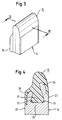
- FIG. 3 and 4 is a first embodiment of the invention Web cap 15 shown.
- the web cap 15 made of elastomer Material has a foot 24. This foot 24 extends to Web 14 and engages in undercuts 25 of the web. The Web cap 15 is thereby reliably prevented from being pulled off Web 14 secured.
- the web 14 has two cross sections provided essentially club-shaped approaches 26. These will encompassed by the web cap 15. Because of the essentially club-shaped The cross-sections act on pulling off the Bridge cap 15 counter.
- the web cap 15 closes both on the outside 27 and the inside 28 flush with the web 14. This will create a continuous smooth surface provided that the overall visual impression significantly improved.
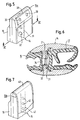
- FIGS. 5 and 6 show a further embodiment of an inventive one Web cap 15a shown in a view according to Figure 3.
- An insert 30 is vulcanized into the web cap 15a.
- This Insert 30 has a latching foot 31 for attachment to the web 14 on.
- the insert 30 has recesses 33 for reducing weight Mistake. At the same time, the recesses 33 improve the connection between the insert 30 and the web cap 15a.
- An elastically movable latching tongue is attached to the latching foot 31 32 arranged. As shown in Figure 6, this latching tongue engages 32 in the assembled state of the web cap 15a in a recess 34 of the web 15 a. For assembly, the web cap 15a is opened from above placed the web 14 and then moved down. The The latching tongue 32 automatically engages in the recess 34. An additional assembly tool is not required. The bridge cap 15a is reliably attached to the web 14 after it has snapped into place.
- the anchoring element is 24, 31 attached to the web cap 15.
- FIG. 7 shows a third embodiment of an inventive Bridge cap 15b.
- the web cap 15b is covered by a cap 40 and is only visible in its edge area.
- the cap 40 connects directly to the web 14 and is made of aluminum. This allows the color of the cap 40 to match that of the web be adjusted so that a continuous uniform for the viewer Surface arises.
- the cap 40 has an anchoring element 41, which passes through the web cap 15b.
- the anchoring element 41 is with schematically illustrated recesses 42 Mistake. These recesses 42 reduce the weight of the anchoring element 41.
- a locking tongue can be used for attachment to the web 14.
- the anchoring elements 24, 31, 41 with respect to the environment covered and not visible from the outside.
- the outside the web cap 15 can be independent of the anchoring elements 24, 31, 41 designed and adapted to the web 14. Therefore, a secure anchoring of the web cap 15 is improved overall visual impression achieved.
Landscapes
- Engineering & Computer Science (AREA)
- Mechanical Engineering (AREA)
- Seal Device For Vehicle (AREA)
- Gates (AREA)
- Body Structure For Vehicles (AREA)
- Vehicle Interior And Exterior Ornaments, Soundproofing, And Insulation (AREA)
Applications Claiming Priority (2)
| Application Number | Priority Date | Filing Date | Title |
|---|---|---|---|
| DE19926955A DE19926955B4 (de) | 1999-06-14 | 1999-06-14 | Stegkappe aus gummielastischem Material |
| DE19926955 | 1999-06-14 |
Publications (3)
| Publication Number | Publication Date |
|---|---|
| EP1060931A2 true EP1060931A2 (fr) | 2000-12-20 |
| EP1060931A3 EP1060931A3 (fr) | 2002-01-02 |
| EP1060931B1 EP1060931B1 (fr) | 2003-11-05 |
Family
ID=7911103
Family Applications (1)
| Application Number | Title | Priority Date | Filing Date |
|---|---|---|---|
| EP00110658A Expired - Lifetime EP1060931B1 (fr) | 1999-06-14 | 2000-05-18 | Capuchon pour montant en matière élastique |
Country Status (4)
| Country | Link |
|---|---|
| US (1) | US6422639B1 (fr) |
| EP (1) | EP1060931B1 (fr) |
| DE (2) | DE19926955B4 (fr) |
| ES (1) | ES2209718T3 (fr) |
Cited By (2)
| Publication number | Priority date | Publication date | Assignee | Title |
|---|---|---|---|---|
| DE102008027926A1 (de) * | 2008-06-12 | 2009-12-24 | Küster Holding GmbH | Vorrichtung zur Anhebung und Absenkung einer vorderen Dreiecksscheibe einer rahmenlosen Kraftfahrzeugtüre, Verstelleinrichtung sowie Verfahren zum Betrieb einer Verstelleinrichtung |
| EP2363310A1 (fr) * | 2010-02-24 | 2011-09-07 | Audi AG | Véhicule automobile avec une porte pivotante dotée d'une fenêtre sans cadre |
Families Citing this family (15)
| Publication number | Priority date | Publication date | Assignee | Title |
|---|---|---|---|---|
| DE19906927B4 (de) * | 1999-02-19 | 2007-09-06 | Audi Ag | Fenstersteg für ein Fahrzeug |
| DE102004019115B3 (de) * | 2004-04-20 | 2006-01-05 | Metzeler Automotive Profile Systems Gmbh | Verfahren zum Herstellen eines Dicht- oder Zierstreifens, insbesondere für ein Kraftfahrzeug, sowie ein solcher Dicht- oder Zierstreifen |
| DE102004019116B3 (de) * | 2004-04-20 | 2006-01-05 | Metzeler Automotive Profile Systems Gmbh | Verfahren zum Herstellen eines Dicht- oder Zierstreifens, insbesondere für ein Kraftfahrzeug, sowie ein solcher Dicht- oder Zierstreifen |
| GB2419371A (en) * | 2004-10-20 | 2006-04-26 | Gdx Automotive Rehburg Gmbh & | Sealing, trimming or guiding strips |
| JP4704067B2 (ja) | 2005-02-25 | 2011-06-15 | マツダ株式会社 | 車両のガラスガイド構造 |
| JP4640023B2 (ja) * | 2005-08-02 | 2011-03-02 | 三菱自動車工業株式会社 | ドア構造 |
| JP4701911B2 (ja) * | 2005-08-08 | 2011-06-15 | 三菱自動車工業株式会社 | 車両用ドアの窓開口構造 |
| CA2619865A1 (fr) * | 2005-08-18 | 2007-02-22 | Cooper-Standard Automotive Inc. | Joint d'etancheite comprenant un capteur de pincement, nouveaux capteurs de pincement et procedes associes |
| JP4478711B2 (ja) * | 2007-12-10 | 2010-06-09 | 片山工業株式会社 | 車両用ドアにおける窓ガラス用センターチャンネル |
| DE102008057995A1 (de) * | 2008-11-19 | 2010-05-20 | Dr. Ing. H.C. F. Porsche Aktiengesellschaft | Kraftfahrzeugtür |
| DE102010061103A1 (de) * | 2010-12-08 | 2012-06-14 | Richard Fritz Gmbh + Co. Kg | Scheibeneinheit und Verfahren zu deren Herstellung |
| JP5705530B2 (ja) * | 2010-12-22 | 2015-04-22 | 西川ゴム工業株式会社 | 格納式ルーフ車用ウェザーストリップのシール構造 |
| DE202011000804U1 (de) * | 2011-04-06 | 2012-07-09 | Richard Fritz Gmbh + Co. Kg | Scheibeneinheit für Fenster an Kraftfahrzeugen |
| US9211781B2 (en) * | 2012-08-31 | 2015-12-15 | Honda Motor Co., Ltd. | Vehicle door |
| DE102017222067A1 (de) * | 2017-12-06 | 2019-06-06 | Bayerische Motoren Werke Aktiengesellschaft | Stabilisierungsvorrichtung für die abdichtung eines spiegeldreiecks sowie damit versehene abdichtungsanordnung |
Family Cites Families (8)
| Publication number | Priority date | Publication date | Assignee | Title |
|---|---|---|---|---|
| JPS5373726A (en) * | 1976-12-09 | 1978-06-30 | Toyota Motor Corp | Door window frame structure for vehicle |
| US4348046A (en) * | 1979-07-16 | 1982-09-07 | Toyo Kogyo Co., Ltd. | Rear side door structure for a four-door type automobile |
| DE3029765A1 (de) * | 1980-08-06 | 1982-03-04 | Dr.Ing.H.C. F. Porsche Ag, 7000 Stuttgart | Haltesteg zur aufnahme von zwei aneinandergesetzten sichtscheiben, insbesondere an vorderen kraftfahrzeugtueren |
| DE3525540A1 (de) * | 1985-07-17 | 1987-01-29 | Bosch Siemens Hausgeraete | Mit einer dichtung versehene tuer, insbesondere doppelseitig verkleidete, waermeisolierte tuer fuer kuehlschraenke und dgl. |
| GB8725836D0 (en) * | 1987-11-04 | 1987-12-09 | Avon Ind Polymers | Grips for handles |
| FR2694243B1 (fr) * | 1992-07-29 | 1994-10-21 | Technistan Gie | Ensemble d'habillage de portière. |
| DE19701681C1 (de) * | 1997-01-18 | 1998-04-23 | Webasto Tuersysteme Gmbh | Dichtungssystem für eine Tür, vorzugsweise an einem Fahrzeug |
| DE19906927B4 (de) * | 1999-02-19 | 2007-09-06 | Audi Ag | Fenstersteg für ein Fahrzeug |
-
1999
- 1999-06-14 DE DE19926955A patent/DE19926955B4/de not_active Expired - Fee Related
-
2000
- 2000-05-18 EP EP00110658A patent/EP1060931B1/fr not_active Expired - Lifetime
- 2000-05-18 DE DE50004298T patent/DE50004298D1/de not_active Expired - Fee Related
- 2000-05-18 ES ES00110658T patent/ES2209718T3/es not_active Expired - Lifetime
- 2000-06-13 US US09/592,626 patent/US6422639B1/en not_active Expired - Fee Related
Non-Patent Citations (1)
| Title |
|---|
| None |
Cited By (3)
| Publication number | Priority date | Publication date | Assignee | Title |
|---|---|---|---|---|
| DE102008027926A1 (de) * | 2008-06-12 | 2009-12-24 | Küster Holding GmbH | Vorrichtung zur Anhebung und Absenkung einer vorderen Dreiecksscheibe einer rahmenlosen Kraftfahrzeugtüre, Verstelleinrichtung sowie Verfahren zum Betrieb einer Verstelleinrichtung |
| DE102008027926B4 (de) * | 2008-06-12 | 2014-05-28 | Küster Holding GmbH | Vorrichtung zur Anhebung und Absenkung einer vorderen Dreiecksscheibe einer rahmenlosen Kraftfahrzeugtüre, Verstelleinrichtung sowie Verfahren zum Betrieb einer Verstelleinrichtung |
| EP2363310A1 (fr) * | 2010-02-24 | 2011-09-07 | Audi AG | Véhicule automobile avec une porte pivotante dotée d'une fenêtre sans cadre |
Also Published As
| Publication number | Publication date |
|---|---|
| DE19926955B4 (de) | 2004-09-30 |
| EP1060931A3 (fr) | 2002-01-02 |
| US6422639B1 (en) | 2002-07-23 |
| EP1060931B1 (fr) | 2003-11-05 |
| DE50004298D1 (de) | 2003-12-11 |
| DE19926955A1 (de) | 2001-04-05 |
| ES2209718T3 (es) | 2004-07-01 |
Similar Documents
| Publication | Publication Date | Title |
|---|---|---|
| EP1060931A2 (fr) | Capuchon pour montant en matière élastique | |
| EP0338974B1 (fr) | Dispositif d'étanchéité pour portes sans seuil | |
| EP2463134B1 (fr) | Joint d'étanchéité pour un moudle de vitrage y compris le procédé de fabrication | |
| DE4309088C2 (de) | Ortsfest einbaubare Scheibe für Kraftfahrzeuge | |
| DE3901093C2 (de) | Kraftfahrzeugtür | |
| DE19711487A1 (de) | Dichtungsprofil für Kraftfahrzeuge | |
| DE19745750C5 (de) | Kämpfer-Verbinder für Fenster- und Türrahmen | |
| DE19961873C2 (de) | Eckenausbildung am Fensterrahmen einer Fahrzeugtür | |
| DE19854775B4 (de) | Kraftfahrzeugtür mit einem Tür-Rahmenmodul | |
| EP4146886B1 (fr) | Boîtier pour utilisations associées à un véhicule automobile | |
| DE19832379C2 (de) | Schiebedach für ein Kraftfahrzeug | |
| DE10066168B4 (de) | Dichtungsanordnung für ein Kraftfahrzeug und Verfahren zur Montage eines Führungs- und Dichtungsprofils an einem Rahmen | |
| DE19514963A1 (de) | Kraftfahrzeugtür | |
| DE10230682B4 (de) | Dichtungsanordnung zum Abdichten eines Spalts, insbesondere an einem Kraftfahrzeug | |
| EP2947228B1 (fr) | Fenêtre de toit | |
| DE19816690A1 (de) | Dichtungsprofil zur Abdichtung des Fensterschachts | |
| DE3149189A1 (de) | Fenster, insbesondere nach aussen zu oeffnendes fenster | |
| DE102017000276A1 (de) | Kraftfahrzeugtür mit Türrahmen | |
| EP1260667B1 (fr) | Connexion d'un seuil à un dormant de porte | |
| DE4325696C1 (de) | Verbindungselement | |
| DE202008011771U1 (de) | Dichtungsanordnung | |
| DE4225974C2 (de) | Kurbelfenster in der Fahrerhaustür eines Lkw | |
| EP4026979A1 (fr) | Installation de porte hermétique | |
| DE10350144B3 (de) | Dichtungsanordnung für eine Fensterscheibe eines Fahrzeugs | |
| DE19857384C2 (de) | Befestigungsmittel zum Verbinden eines Flügelrahmens mit einem Blendrahmen zu einem nicht öffenbaren Fenster |
Legal Events
| Date | Code | Title | Description |
|---|---|---|---|
| PUAI | Public reference made under article 153(3) epc to a published international application that has entered the european phase |
Free format text: ORIGINAL CODE: 0009012 |
|
| AK | Designated contracting states |
Kind code of ref document: A2 Designated state(s): DE ES FR GB IT Kind code of ref document: A2 Designated state(s): AT BE CH CY DE DK ES FI FR GB GR IE IT LI LU MC NL PT SE |
|
| AX | Request for extension of the european patent |
Free format text: AL;LT;LV;MK;RO;SI |
|
| PUAL | Search report despatched |
Free format text: ORIGINAL CODE: 0009013 |
|
| AK | Designated contracting states |
Kind code of ref document: A3 Designated state(s): AT BE CH CY DE DK ES FI FR GB GR IE IT LI LU MC NL PT SE |
|
| AX | Request for extension of the european patent |
Free format text: AL;LT;LV;MK;RO;SI |
|
| 17P | Request for examination filed |
Effective date: 20020322 |
|
| 17Q | First examination report despatched |
Effective date: 20020625 |
|
| AKX | Designation fees paid |
Free format text: DE ES FR GB IT |
|
| RAP1 | Party data changed (applicant data changed or rights of an application transferred) |
Owner name: METZELER AUTOMOTIVE PROFILE SYSTEMS GMBH |
|
| GRAH | Despatch of communication of intention to grant a patent |
Free format text: ORIGINAL CODE: EPIDOS IGRA |
|
| GRAA | (expected) grant |
Free format text: ORIGINAL CODE: 0009210 |
|
| GRAS | Grant fee paid |
Free format text: ORIGINAL CODE: EPIDOSNIGR3 |
|
| AK | Designated contracting states |
Kind code of ref document: B1 Designated state(s): DE ES FR GB IT |
|
| REG | Reference to a national code |
Ref country code: GB Ref legal event code: FG4D Free format text: NOT ENGLISH |
|
| REF | Corresponds to: |
Ref document number: 50004298 Country of ref document: DE Date of ref document: 20031211 Kind code of ref document: P |
|
| REG | Reference to a national code |
Ref country code: IE Ref legal event code: FG4D Free format text: GERMAN |
|
| GBT | Gb: translation of ep patent filed (gb section 77(6)(a)/1977) |
Effective date: 20040204 |
|
| REG | Reference to a national code |
Ref country code: IE Ref legal event code: FD4D |
|
| REG | Reference to a national code |
Ref country code: ES Ref legal event code: FG2A Ref document number: 2209718 Country of ref document: ES Kind code of ref document: T3 |
|
| ET | Fr: translation filed | ||
| PLBE | No opposition filed within time limit |
Free format text: ORIGINAL CODE: 0009261 |
|
| STAA | Information on the status of an ep patent application or granted ep patent |
Free format text: STATUS: NO OPPOSITION FILED WITHIN TIME LIMIT |
|
| 26N | No opposition filed |
Effective date: 20040806 |
|
| PGFP | Annual fee paid to national office [announced via postgrant information from national office to epo] |
Ref country code: ES Payment date: 20070525 Year of fee payment: 8 |
|
| PGFP | Annual fee paid to national office [announced via postgrant information from national office to epo] |
Ref country code: DE Payment date: 20070531 Year of fee payment: 8 |
|
| PGFP | Annual fee paid to national office [announced via postgrant information from national office to epo] |
Ref country code: GB Payment date: 20070523 Year of fee payment: 8 |
|
| PGFP | Annual fee paid to national office [announced via postgrant information from national office to epo] |
Ref country code: IT Payment date: 20070526 Year of fee payment: 8 |
|
| PGFP | Annual fee paid to national office [announced via postgrant information from national office to epo] |
Ref country code: FR Payment date: 20070518 Year of fee payment: 8 |
|
| GBPC | Gb: european patent ceased through non-payment of renewal fee |
Effective date: 20080518 |
|
| REG | Reference to a national code |
Ref country code: FR Ref legal event code: ST Effective date: 20090119 |
|
| PG25 | Lapsed in a contracting state [announced via postgrant information from national office to epo] |
Ref country code: FR Free format text: LAPSE BECAUSE OF NON-PAYMENT OF DUE FEES Effective date: 20080602 Ref country code: DE Free format text: LAPSE BECAUSE OF NON-PAYMENT OF DUE FEES Effective date: 20081202 |
|
| PG25 | Lapsed in a contracting state [announced via postgrant information from national office to epo] |
Ref country code: GB Free format text: LAPSE BECAUSE OF NON-PAYMENT OF DUE FEES Effective date: 20080518 |
|
| REG | Reference to a national code |
Ref country code: ES Ref legal event code: FD2A Effective date: 20080519 |
|
| PG25 | Lapsed in a contracting state [announced via postgrant information from national office to epo] |
Ref country code: IT Free format text: LAPSE BECAUSE OF NON-PAYMENT OF DUE FEES Effective date: 20080518 |
|
| PG25 | Lapsed in a contracting state [announced via postgrant information from national office to epo] |
Ref country code: ES Free format text: LAPSE BECAUSE OF NON-PAYMENT OF DUE FEES Effective date: 20080519 |