EP1060923A2 - Vehicle roof - Google Patents
Vehicle roof Download PDFInfo
- Publication number
- EP1060923A2 EP1060923A2 EP00112517A EP00112517A EP1060923A2 EP 1060923 A2 EP1060923 A2 EP 1060923A2 EP 00112517 A EP00112517 A EP 00112517A EP 00112517 A EP00112517 A EP 00112517A EP 1060923 A2 EP1060923 A2 EP 1060923A2
- Authority
- EP
- European Patent Office
- Prior art keywords
- roof
- vehicle
- roof part
- locking
- cassette
- Prior art date
- Legal status (The legal status is an assumption and is not a legal conclusion. Google has not performed a legal analysis and makes no representation as to the accuracy of the status listed.)
- Granted
Links
- 241000446313 Lamella Species 0.000 claims description 2
- 230000007246 mechanism Effects 0.000 abstract description 4
- 238000010168 coupling process Methods 0.000 description 19
- 230000008878 coupling Effects 0.000 description 15
- 238000005859 coupling reaction Methods 0.000 description 15
- 238000006073 displacement reaction Methods 0.000 description 12
- 239000000523 sample Substances 0.000 description 7
- 238000005192 partition Methods 0.000 description 6
- 230000006835 compression Effects 0.000 description 5
- 238000007906 compression Methods 0.000 description 5
- 238000001514 detection method Methods 0.000 description 4
- 230000001939 inductive effect Effects 0.000 description 4
- 241001422033 Thestylus Species 0.000 description 3
- 230000009471 action Effects 0.000 description 3
- 238000013459 approach Methods 0.000 description 2
- 230000000295 complement effect Effects 0.000 description 2
- 239000000463 material Substances 0.000 description 2
- 239000004575 stone Substances 0.000 description 2
- 238000012546 transfer Methods 0.000 description 2
- 230000008901 benefit Effects 0.000 description 1
- 230000000903 blocking effect Effects 0.000 description 1
- 230000001419 dependent effect Effects 0.000 description 1
- 238000013461 design Methods 0.000 description 1
- 238000010586 diagram Methods 0.000 description 1
- 230000000694 effects Effects 0.000 description 1
- 238000004049 embossing Methods 0.000 description 1
- 230000003993 interaction Effects 0.000 description 1
- 238000000034 method Methods 0.000 description 1
- 238000012806 monitoring device Methods 0.000 description 1
- 230000036316 preload Effects 0.000 description 1
- 238000003825 pressing Methods 0.000 description 1
- 230000008569 process Effects 0.000 description 1
- 239000007787 solid Substances 0.000 description 1
- 238000012549 training Methods 0.000 description 1
Images


Classifications
-
- B—PERFORMING OPERATIONS; TRANSPORTING
- B60—VEHICLES IN GENERAL
- B60J—WINDOWS, WINDSCREENS, NON-FIXED ROOFS, DOORS, OR SIMILAR DEVICES FOR VEHICLES; REMOVABLE EXTERNAL PROTECTIVE COVERINGS SPECIALLY ADAPTED FOR VEHICLES
- B60J7/00—Non-fixed roofs; Roofs with movable panels, e.g. rotary sunroofs
- B60J7/0053—Collapsible lateral roof side beams
-
- B—PERFORMING OPERATIONS; TRANSPORTING
- B60—VEHICLES IN GENERAL
- B60J—WINDOWS, WINDSCREENS, NON-FIXED ROOFS, DOORS, OR SIMILAR DEVICES FOR VEHICLES; REMOVABLE EXTERNAL PROTECTIVE COVERINGS SPECIALLY ADAPTED FOR VEHICLES
- B60J7/00—Non-fixed roofs; Roofs with movable panels, e.g. rotary sunroofs
- B60J7/02—Non-fixed roofs; Roofs with movable panels, e.g. rotary sunroofs of sliding type, e.g. comprising guide shoes
- B60J7/06—Non-fixed roofs; Roofs with movable panels, e.g. rotary sunroofs of sliding type, e.g. comprising guide shoes with non-rigid element or elements
- B60J7/061—Non-fixed roofs; Roofs with movable panels, e.g. rotary sunroofs of sliding type, e.g. comprising guide shoes with non-rigid element or elements sliding and folding
Definitions
- the invention relates to a vehicle roof with at least one of one Drive motor operable openable roof part and at least one temporarily fixed roof part, which the openable roof part in its Open position.
- an electric drive is arranged, which Unlocking the side rails from the cross member causes a second electrical Drive in the rear roof part takes over the shifting of the openable Roof part and another, also attached in the area of the rear roof part electric drive serves to pivot the side rails. Furthermore, a Hydraulic cylinder in the area of the rear vehicle side walls available for a pivoting of the rear roof part together with that of the rear Roof part of the openable roof part, attached to the rear roof part pivoted side rails and rear pillars (C pillars) on which the rear roof part rests on both sides, ensures.
- the invention specified in claim 1 is based on the object To create vehicle roof of the type mentioned, without an expensive Actuating mechanism works, convenient to use and universal can be used.
- the temporarily fixed roof part is preferably a rear roof part and the at least temporarily fixed roof part especially around the rear side pillars (B or C pillars) of the vehicle.
- the openable can be used to increase the operational safety of the vehicle roof Roof part can be locked in the open position in the temporarily fixed roof part, the locking of the openable roof part in the temporarily fixed Roof part is preferably operated by the drive motor.
- the design effort of the vehicle roof can be kept low if the Drive motor is fixed on the temporarily fixed roof part.
- the rear roof part is temporary fixed roof part after unlocking it at least temporarily fixed roof part, especially after unlocking from the rear pillars (B or C pillars), can be lowered.
- the rear roof section can be made using a Four-bar arrangement are lowered, preferably to the extent that one Top of the rear roof part at about the level of the belt line of the vehicle comes to lie.
- the temporarily fixed Roof part after it has been unlocked from the at least temporarily fixed roof part completely removed from the vehicle.
- the rear pillars of the vehicle can be lowered, one can Convertible roof opening without the belt line protruding upwards Body parts in the rear area of the vehicle are released.
- an automatic extension of the rear pillars can be provided, as soon as an electronic monitoring device threatens to roll over of the vehicle registered.
- the drive motor which is used to actuate the opening and closing movement of the openable roof part and for actuating the lock and / or Unlocking the temporarily fixed roof part with respect to the at least temporarily used roof part can also be used to operate a Locking the rear roof part in the lowered position and / or a release same from the lowered position.
- Actuated in particular the drive motor is a locking device, which is preferably at times fixed roof part is fixed and not only the locking / unlocking of the temporarily fixed roof part with respect to the at least temporarily fixed roof part, but also with reference, for example, to the Lowering movement of the temporarily fixed roof part Four-joint arrangement is used.
- at least at times fixed roof part and arranged a counter bearing on the four-bar arrangement be, which interacts with the closure device.
- a rear part of the vehicle can be fixed on the rear roof part includes a rear window. If the rear roof section is designed to be lowerable, then so the rear window is preferably made of a foldable plastic material.
- Is an underside of the rear part of the vehicle attached to the rear roof part Can be placed on a rear door of the vehicle and folded upwards in particular the accessibility to one located in the area of the rear of the vehicle Improve storage space.
- the openable roof part can be a while driving Openable roof part like a folding roof or a lamella roof in principle act in a known manner. It is understood that within the scope of the present Invention as an openable roof part also a sunroof or Sunroof with one or more lids, preferably with two Lids that can be used.
- a vehicle 10 with a vehicle roof 1 which a drive motor designed as an electric motor 222 openable roof part, a temporarily fixed roof part, at least one temporarily fixed roof part, a rear part 6 and side rails 28 includes.
- the openable roof part is a folding roof 30, which in guides of the temporarily fixed roof part and in those of the side rails 28 in opening or Closing direction 32 slidably received and in any Intermediate positions between its open position (see FIGS. 2, 3 and 5) and its closed position (see FIGS. 1 and 6) can be brought.
- Folding roof 30 in the temporarily fixed roof part which in the illustrated embodiment designed as a roof cassette 12 rear roof part of the vehicle roof 1 is mounted, all in the guides displaceable parts of the folding roof 30 arranged in the roof cassette 12 Guides are included and can be locked with reference to the roof cassette 12, as described below in connection with FIGS. 7 to 12 is explained in more detail.
- the folding roof 30 is in the open position as far back in the opening direction 32 moved that its rooftop 149 is essentially flush with one Front edge of the roof cassette 12 closes.
- the guides arranged in the roof cassette 12 are by Guide rail sections 22 formed on the locking devices 14th are attached, which in turn are fixed to the roof cassette 12, the Guide rail sections 22 with front guide rail sections 26 in Alignment if the roof cassette 12 at least temporarily with respect to that fixed roof part is locked.
- the front guide rail sections 26 form the existing guides in the side rails 28 and are floating in the side rails 28 added.
- the side rails 28 are detachable with the Vehicle 10 connected, for which purpose in the area of the joint between a front, above the windshield crossmember 2 and front side Pillars (A pillars 3) front side rail bearing 13 and in the area of the upper End of an at least temporarily fixed additional roof part rear pillars (B pillars 20) rear side rail bearings 15 are provided.
- the expanded Side rails 28 can be in the vehicle 10 in corresponding Place cradles, for example in a tailgate 5.
- the rear side pillars i.e. the B-pillars 20, at least temporarily fixed roof part.
- a rear cross member 4 in the manner of a roll bar extend.
- One closure device 14 is on the attached to the left and right side of the roof cassette 12 in the direction of travel and interacts with a counter bearing 11 which is close to an upper end of each of the B-pillars 20 is fixed to be actuated via the electric motor 222 Locking and unlocking the roof cassette 12 with respect to the B-pillars 20 to effect.
- the rear part 6 of the vehicle roof 1 is fixed to the roof cassette 12 and includes a rear window 18 made of foldable plastic material as well foldable side parts 16.
- the roof cassette 12 is over a not shown Four-joint arrangement connected to the vehicle body and after unlocking from the counter bearing 11 of the B-pillars 20 so far that an upper side of the Roof cassette 12 to lie essentially at the level of the vehicle belt line is coming.
- the Four-joint arrangement itself also provided a counter bearing, with which the Locking device 14 in a similar manner as with the counter bearing 11 interacts.
- An underside 7 of the rear part 6 can be placed against a rear door 5 and can, as shown in Fig.
- the tailgate 5 in turn, its underside is pivotally connected to the vehicle body and can be independent of the position which the underside 7 of the rear part 6 occupies and also folded back with the roof cassette 12 lowered become.
- a Lock latch for the tailgate 5 can be on the bottom 7 of the rear part 6
- Cross member may be arranged.
- FIGS. 7 to 12 two embodiments of the Closure device 14 described in detail, with two on the roof cassette 12 mirror-image closure devices are attached, but only the Left closure device 14 seen in the direction of travel in the figures is reproduced. All versions regarding the left locking device 14 also refer to the mirror image rights Locking device. It should also be noted that the in Fig. 7 to 11 with X designated axis in the opening direction of the folding roof 30, i.e. in the same Direction as the arrow 32 pointing towards the vehicle in FIG. 2 points.
- the two closure devices are symmetrical to one in Vehicle longitudinal axis of symmetry inside the roof cassette 12 mounted near their lateral outer surfaces in such a way that they are attached to the other B pillars 20 attached counter bearings 11 can be set, wherein at the same time with the guide rail sections 22 of the closure devices 14 the front guide rail sections 26 of the side rails 20 in alignment be aligned by one fixed on the guide rail section 22 Alignment bar 24 as an alignment member in engagement with the front Guide rail sections 26 is brought.
- the closure device 14 comprises a bearing plate 34 with an as Recording groove 48 trained receiving member into which a bolt 46 of the the B-pillar 20 attached counter bearing 11 in the direction of displacement 50 (see FIG. 9) inserted and by means of a locking groove 42 of a locking hook 36 can be locked.
- the locking groove 42 is in a front arm 38 of the locking hook 36 is placed, which is pivotable about a bearing pin 56 in a bent bearing lever 58 is added.
- the bearing pin 56 of the Locking hook 36 is approximately in the middle between which the locking groove 42 comprising front arm 38 and a rear arm 40, the Locking hook 36 about the axis of the bearing pin 56 in the pivoting direction 44 (see Fig. 7) between one in Figs. 7, 9 and 10 shown locking and a release position is pivotable, in the locked position Locking hook 36 also between a broken line in Fig. 9 reproduced front locking position 52 and a rear locking position 54 in Sliding direction 50 slidable.
- the bearing lever 58 is formed in two parts and comprises two in the Y direction Thickness of a sleeve 62 spaced congruent halves, the spacing so is dimensioned that the locking hook 36 and one described below Control lever 84 can be added between them.
- the socket 62 is open an axis 60 slid on the arm 64 of the bearing lever 58 in the Y direction enforced that it projects beyond the halves of the bearing lever 58 on both sides and on the one hand in the bearing plate 34 and on the other hand in an arm 64 encompassing bearing bracket 59 is held, which in turn on the bearing plate 34th is set.
- the bearing lever 58 is by means of one on its second arm 66 fixed control pin 68 pivotable about the axis 60, the control pin 68 protrudes beyond the bearing lever in the Y direction and into a control track 72 Switching slot 74 engages in which it is guided over a sliding block 70.
- the switching link 74 is integrated in a link body 80, the second Has shifting gate 78, in the control path 76 thereof on the control lever 84 fixed control pin 82 is slidably received and its Swiveling movement about the axis of the bearing pin 56 causes by means of Control lever 84 together with the locking hook 36 in the bearing lever 58 is mounted, the control lever in the direction of the front arm 38 of the Locking hook 36 extends.
- a bend 92 of the control lever 84 engages a recess 85 of the locking hook 36 which is open in the -Z direction and serves to carry the locking hook 36 when the control lever 84 over its control pin 82 is pivoted clockwise by the control track 78 (The terms used clockwise and counterclockwise each refer to an observation in the Y direction).
- a holding lever 89 is pivotable approximately in the middle by a shoulder bolt 91 on the Locking hook 36 in the area between the recess 85 and the Locking groove 42 mounted, with a tension spring 90 between one on one first arm 93 of the holding lever 89 located projection 88 and a bend 86 of the control lever 84 is provided.
- the in first arm 93 of the holding lever 89 above a substantially in the X direction open locking area 98 arranged inclined surface 95 is formed such that about the prestressed contact of the inclined surface 95 on the retaining bolt 87 Force is exerted on the locking hook 36, the latter in Counterclockwise around the axis of the bearing pin 56 rotates, and the Locking hook 36 seen in the longitudinal direction of the vehicle 10 located behind the locking groove 42 (i.e., starting from the locking groove 42 offset in the positive X direction), 50 in the displacement direction extending sliding surface 190 rests on a bend 188 of the bearing plate 34.
- the Retaining pin 87 also serves as a catching device into which the latching area 98 of the Holding lever 89 engages when the locking hook 36 is in its Release position is.
- a second arm 94 of the holding lever 89 which is located below the shoulder bolt 91 (i.e., offset with respect to this in the negative Z direction), has an im Projection 97 projecting substantially in the X direction, which in order to Control lever 84 set with respect to the locking hook 36 to one Bottom of the bend 92 of the control lever 84 can be applied as soon as the Locking hook 36 approaches its rear latching position 54.
- a total of 100, essentially in the X direction extending alignment plate is with the bearing plate 34 via a plurality of screws 99 connected, which is simultaneously a lower area of the guide rail section 22, which also has blind rivets (not shown) in its upper section Area is fixed directly to the bearing plate 34, with a solid cohesion achieved by bearing plate 34, guide rail section 22 and alignment plate 100 becomes.
- the guide rail section 22 has a lower and an upper slideway 101 or 102, which by a partition 104 extending in the X-Z plane are separated from each other.
- the lower slideway 101 is laterally from the partition 104 and a rear wall of the bearing plate 34 and up and down through Legs that extend from the partition 104 in the -Y direction, limited and open in +/- X direction.
- the link body 80 is in the +/- X direction slidable between a rear and a front end position.
- the slideway 102 is up and down by extending in the Y direction Limits 112 and 110 and by means of perpendicular to the legs 110 and 112 arranged webs 109 divided into at least two open chambers 111, 113, of which the inner chamber 111 of receiving a driving slider 114 and the outer chamber 113 serves to receive a roof glider 116.
- Both Gliders 114 and 116 can be moved in the +/- X direction, with the driving glider 114 the pressure-resistant cable 174 is attached, which over the on the Roof cassette 12 fixed electric motor 222 (see FIG. 2) is movable and in a cable duct 118 is guided, the side next to the slideway 102 in the Partition 104 is added.
- a tactile slide 120 which can be displaced in the +/- X direction as part of a Counter bearing detection device added by the action of an intermediate the slide slider 120 and the alignment plate 100 attached tension spring 122 in the -X direction is biased such that its stylus tip 124 has a leading edge 125 of the guide rail section 22 protrudes.
- a release 126 arranged with a release arm 128 of a bent locking lever 130 interacts, which in turn is pivotable about an axis 131 between the Bearing plate 34 and the alignment plate 100 is mounted.
- a locking lug 133 is provided, which is designed in a complementary shaped, not shown leading edge on the underside of the Link body 80 to engage when the link body 80 is in a behind warning position located in its front end position.
- the Warning position of the link body 80 with respect to the bearing plate 34 on a Place arranged between the front and rear end positions of the Link body 80 is located the front end position of a smaller X coordinate corresponds to the rear end position.
- the locking lever 130 is by means of a spring arm 134 a two spring arms 134 and 136 comprehensive combination spring 138 loaded counterclockwise, so that the Locking lug 133 biased when the link body 80 is in the warning position bears against its leading edge and prevents the link body 80 from being reaches the front end position if the counter bearing 11 is not in its desired position Regarding the closure device 14 is located.
- the backdrop body is in this Fall only between its rear end position and its warning position.
- the second spring arm 136 of the Combi spring 138 is biased upwards in the Z direction and can counteract it Bias down from the rear arm 40 of the locking hook 36 be deflected when the locking hook 36 is in its release position located.
- the spring arm 136 is biased in its upward direction Home position actuated an electrical microswitch 140, which together with the Combination spring 138 is fixed to the bearing plate 34, the microswitch 140 being a Corresponding signal "locking hook in locking position" delivers.
- This The signal is used as an input variable in a motorized operation of the Electronic control 218 controlling closure device 14 (see FIG. 13) fed, which also control the motorized operation of the opening and Closing movement of the folding roof 30 takes over.
- the spring arm 136 instead of its resilient Preload upwards with the rear arm 40 of the To connect locking hook 36 so that the latter the spring arm 136 in both Directions, i.e., up and down, operated.
- the tactile glider 120 when Coupling process of the closure device 14 to the counter bearing from Side spar 28 operated and moved in the X direction so far that the Locking lug 133 of the locking lever 130 no longer holds the link body 80 in its Warning position locked.
- the side rail 28 is removed from the vehicle or for some other reason it is not in its target position with respect to the locking device 14 in the coupling position, the probe tip 124 at Coupling process not operated or not operated far enough in the X direction and the Link body 80 locked when it reaches its warning position, even if that Counter bearing is in the target position.
- the counter bearing detection device used in principle for side post recognition. This has the further advantage that when coupling the closure device 14 to the further counter bearing, which is attached to the four-bar linkage, the link body 80 no further than into it Warning position can be moved, because that is at the four-bar linkage The intended counter bearing is in the target position, but a side rail is not available is. This prevents the locking of the Rooftop glider 116 is released with respect to the closure device 14, when the locking device 14 is coupled to the counter bearing of the four-bar linkage becomes.
- An alignment fork 152 at a front end of the alignment plate 100 is used for Alignment of the closure device 14 in the Y and Z directions with respect to the front guide rail section 26, for which purpose the alignment fork 152 engages in a complementarily shaped alignment bearing, which is a unit with the front guide rail section 26 floating in the side rail 28 forms.
- the on the guide rail section 22 of the closure device 14 fixed alignment bar 24, which is in the Z direction above the alignment fork 152 is located and brought into engagement with the front guide rail section 26 prevents tilting around the X axis of the front Guide rail section 26 with respect to the guide rail section 22.
- An alignment surface 150 is on a side surface of the alignment fork 152 in the X-Z plane located and on the end face of the bolt 46 on the B-pillar 20th attached counter bearing 11 can be applied, so that in cooperation with the mirror-image right locking device and the right bolt one in the Y direction seen symmetrical alignment of the entire roof cassette 12 with Reference is made to the two bolts 46 of the counter bearing 11.
- End position spring 146 which comprises two spring arms 142 and 144, one of which the spring arm 142 engages from below into the chamber 113 in which the Rooftop glider 116 is included, which with a rooftop 149 of the Folding roof 30 is connected and the opening and closing movement of the same causes.
- the second spring arm 144 is designed, an electrical microswitch 148 to operate mechanically when the Dachspitze glider 116 in a Stop position, the microswitch 148 the signal "Dachspitzeglider in Stop position "to the electronic control 218 (see FIG. 13).
- the rooftop glider 116 is fully in that position Guide rail section 22 of the closure device 14 and can be locked with respect to the guide rail section 22. With the Dachspitzengliter 116 are all movable parts of the folding roof 30 in the Guide rail section 22 held and together with the roof cassette 12th be decoupled from the counter bearing 11.
- the controller 218 receives for the vehicle roof in addition to the signals of two switch positions ("open” and “close") having actuating switch 224 also the signals of two sensors 226 and 228 as input variables.
- the operating switch 224 can be operated by the operator and serves to initiate both the opening and closing movement of the folding roof as well as the coupling and uncoupling movement of the closure device, with about the swiveling and sliding movements of the locking hook Locking and unlocking the roof cassette 12 with respect to the counter bearing 11 on the B-pillars 20 is effected.
- Two actuation switches can be provided, one of which is the opening and Closing movement of the folding roof and one when the folding roof is fully open initiates the coupling and uncoupling movement of the closure device.
- Both both sensors 226 and 228 are in the case of the first embodiment the locking device (shown in FIGS. 7 to 11) around the microswitch 148 or 140.
- an inductive sensor 216 is used.
- the roof tip glider 116 and the Driving sliders 114 in the front guide rail section 26 and positively connected to one another by means of a locking block 164, in the Z direction is slidably received in the roof tip glider 116.
- the Roof cassette 12 is on the locking devices 14 on the B-pillars 20 of the Vehicle 10 fixed, the locking hook 36 in Locking position stops in its rear latching position 54.
- the backdrop body 80 is in its front end position and is in this in the Y direction Slidably mounted locking block 156, which by means of a compression spring 160 loaded ball 158 can be locked in its end positions, in a recess 162 Bearing plate 34 held.
- the control pin 82 is Control lever 84 in a holding area 206 of the control track 76 for the Pivoting movement of the locking hook 36 responsible shifting gate 78.
- Der Retaining lever 89 is by abutting its inclined surface 95 on the retaining bolt 87 pivoted counterclockwise so far that its projection 97 the bend 92 of the control lever 84 engages and this with reference to the Locking hook 36 sets.
- the locking hook 36 is ultimately in his Locked position blocked. So that the backdrop body 80 in its front End position must, of course, as described above Counter bearing 11 or the side rail 28 are in the desired position, the key slide 120 actuated and the locking lug 133 of the locking lever 130 out of engagement with respect to the be arranged on the underside of the link body 80 leading edge.
- the folding roof 30 can be opened by the roof tip glider 116 in the opening direction 32 is moved behind.
- the sliding movement becomes the rooftop glider 116 impressed by the slider 114, which in turn by means of the known per se rigid cable 174 is moved over the electric motor 222, which in the Roof cassette 12 is added.
- Both the rooftop glider 116 and the Carriage gliders 114 eventually get from the front Guide rail section 26 in the guide rail section 22 of the Locking device 14, the roof tip glider 116 as soon as it is in its Stop position is reached, abuts a stop 168, which in the Guide rail section 22 is provided and a further displacement of the Rooftop glider 116 prevented to the rear (in the X direction) (see Fig. 11), wherein also, as described above, the electrical microswitch 148 from the spring arm 144 is operated.
- the driving glider 114 now has its one shown in FIG. 11 Transfer position reached.
- the operator continues to operate the switch position "Opening" of the actuation switch 224, then at the control 218 applied signal "rooftop glider in stop position" of the microswitch 148 the Decoupling movement of the closure device initiated, namely preferably only after certain safety conditions have been met. For this can e.g. count that the vehicle may not be moved and / or that the Operator operates switch 224 during a predetermined actuation time must hold in the "Open" switch position.
- the entrainment slider 114 When the uncoupling process is initiated, the entrainment slider 114 first becomes from the electric motor 222 via the compression-resistant cable 174 with a force in the X direction applied so that an inclined surface 170 in the locking block 164th receiving recess 166 in the driving slider 114 a force in the Z direction exercises on the bolt 164, which is sufficient, the latter so far in the Z direction move the latch 164 out of engagement with respect to the recess 166 arrives in the driving glider 114 and with it the driving glider 114 opposite end into a recess 172 in the guide rail section 22 is pushed.
- the roof top glider 116 is thus positively in the Guide rail section held, and the driving slider 114 for another Displacement in the X direction is released, the roof tip glider 116 facing side of the driving slider 114 is designed so that a release of the Positive connection between the roof tip glider 116 and the Guide rail section 22 by moving the locking block 164 in Rooftop glider 116 in the -Z direction is excluded.
- the driving glider 114 comes by means of its Coupling surface 176 on the leading edge 108 of the in the front end position according to Fig.
- the Riegelstein 156 releases the positive connection of the link body 80 with the Bearing plate 34 and at the same time forms one between the link body 80 and the driving glider 114, which the link body 80 in the direction of which rear end position.
- the front detent position is 52 reached when the sliding block 70 is in the lowest point of the ramp-shaped Sliding area 208 of the control path is located and in a front stopping area 212 passes over, in which it is guided essentially horizontally, so that the Bearing lever 58 no longer pivots.
- the catch area 98 comes of the holding lever 89 free from the holding bolt 87, and the locking hook 36 can in pivot its locking position without the control pin 82 this Swiveling movement is hindered because it is outside the control path 76.
- the Locking hook 36 As soon as the Inclined surface 95 of the holding lever 89 rests on the holding bolt, the Locking hook 36, as already described, by the tension spring 90 in the direction biased to the locking position.
- the microswitch 140 is actuated and delivers as Sensor 228 of controller 218 receives the input signal "locking hook in Locking position ".
- the controller 218 releases the automatic The locking hook 36 from closing by the electric motor 222 controls, which in turn the displacement of the link body 80 forward in Actuated towards its front end position.
- the take-along glider 114 is still subjected to a force in the -X direction by the electric motor 222, which has the consequence that the locking block 156 of an inclined surface 182 in the Recess 180 of the driving glider 114 in the -Y direction into the recess 162 in the bearing plate 34 is shifted and at the same time the driving slider 114 from Link body 80 is released.
- the locking block 156 is made by the compression spring 160 loaded ball 158 held in this position, and the automatic The closing device 14 is closed by switching off the Electric motor 222 ended.
- the electric motor 222 is reactivated and moves the slider 114 further forward into the transfer position, where it is connected by means of a coupling surface 184 comes to rest on the rooftop glider 116. It is about compression-resistant cable 174 on the rooftop glider 116 a force forward exercised, sufficient over an inclined surface 186 on a front of the Recess 172 in the guide rail section 22 the locking block 164 of the Rooftop glider 116 in the -Z direction out of the recess 172 and into the To push recess 166 of the driving slider 114 into it.
- FIG. 12 shows an alternative embodiment of a closure device illustrates which differs from that shown in FIGS. 7 to 11 reproduced in The main difference is only that corresponding to a holding lever the holding lever 89 of the first embodiment is omitted and a Locking hook 192 does not have a rear arm corresponding to rear arm 40 of the locking hook 36.
- the resilient bias of the Locking hook 192 in the direction of its locking position is by a tension spring 196 applied, which is between a bend 194 on Locking hook 192 and a retaining lug 198 extends to the bearing plate 34.
- a modified control lever 200 instead of the control pin 82 des Control lever 84 integrally formed on the control lever 200 Control flap 202, which interacts with the control path 76 to the To control pivoting movement of the locking hook 192.
- the fold 92 of the Control lever 200 is located, as is the control lever 84 of the first Embodiment of the closure device is the case, clockwise pretensioned from below on the locking hook 192, but the Biasing force in the second embodiment according to FIG. 12 from the tension spring 90 which, in contrast to the first embodiment, is located between the Bend 86 on the control lever 200 and the bend 194 on the locking hook 192 extends.
- the inductive sensor 216 is used instead, which is actuated by the bolt 46 of the thrust bearing 11 when the bolt 46 is in a position within the receiving groove 48, in which it from the Locking groove 42 of the located in the front locking position 52 Locking hook 192 can be locked. Whether the locking hook 192 actually is pivoted back into the locking position by the inductive sensor 216, which instead of the microswitch 140 as a sensor 228 on the controller 218 is connected, not detected. However, if this is not the case, the The locking hook 192 does not pull toward the counter bearing 11 transmitted so that this does not reach the target position and the probe tip 124 also in principle in the second embodiment of the closure device Counter bearing detection device adopted unchanged not or not far enough in the X direction.
Abstract
Die Erfindung betrifft ein Fahrzeugdach mit wenigstens einem von einem Antriebsmotor (222) betätigbaren öffnungsfähigen Dachteil (30) und wenigstens einem zeitweise feststehenden Dachteil (12), welches das öffnungsfähige Dachteil (30) in dessen Öffnungsstellung lagert. Ein Fahrzeugdach, das ohne eine aufwendige Betätigungsmechanik auskommt, auf komfortable Weise zu bedienen und universell einsetzbar ist, wird geschaffen, indem der Antriebsmotor (222) eine Verriegelung und/oder eine Entriegelung des zeitweise feststehenden Dachteils (12) mit Bezug auf ein zumindest zeitweise feststehendes Dachteil, beispielsweise mit Bezug auf hintere seitliche Säulen (B-Säulen 20) des Fahrzeugs betätigt. Vorzugsweise sind Seitenholme (28), die sich zwischen dem hinteren Dachteil (12) und einem oberhalb der Windschutzscheibe verlaufenden vorderen Querträger (2) zu beiden Seiten des öffnungsfähigen Dachteils (30) erstrecken und welche Führungen (26) für das öffnungsfähige Dachteil (30) umfassen, lösbar mit dem Fahrzeug (10) verbunden. <IMAGE>The invention relates to a vehicle roof with at least one openable roof part (30) which can be actuated by a drive motor (222) and at least one temporarily fixed roof part (12) which supports the openable roof part (30) in its open position. A vehicle roof that does not require any complex actuation mechanism, is easy to operate and can be used universally is created by the drive motor (222) locking and / or unlocking the temporarily fixed roof part (12) with respect to an at least temporarily fixed part Roof part actuated, for example with respect to rear side pillars (B pillars 20) of the vehicle. Side spars (28) which extend between the rear roof part (12) and a front cross member (2) running above the windshield on both sides of the openable roof part (30) and which guides (26) for the openable roof part (30) are preferred. comprise, releasably connected to the vehicle (10). <IMAGE>
Description
Die Erfindung bezieht sich auf ein Fahrzeugdach mit wenigstens einem von einem Antriebsmotor betätigbaren öffnungsfähigen Dachteil und wenigstens einem zeitweise feststehenden Dachteil, welches das öffnungsfähige Dachteil in dessen Öffnungsstellung lagert.The invention relates to a vehicle roof with at least one of one Drive motor operable openable roof part and at least one temporarily fixed roof part, which the openable roof part in its Open position.
Bei einem derartigen, aus der DE 42 03 229 C2 bekannten Fahrzeugdach ist das öffnungsfähige Dachteil während der Fahrt in Führungen von Seitenholmen in Fahrzeuglängsrichtung in beliebige Öffnungspositionen verfahrbar, wobei die Seitenholme an einem hinteren Dachteil als zeitweise feststehendem Dachteil schwenkbar angelenkt, mit einem vorderen oberhalb der Windschutzscheibe verlaufenden vorderen Querträger lösbar verbunden und nach Entriegelung von dem vorderen Querträger an das hintere Dachteil anschwenkbar sind. Das komplette Fahrzeugdach inklusive einer mit dem hinteren Dachteil verbundenen Heckscheibe ist zur Freigabe einer cabrioartigen Dachöffnung in einen Stauraum im hinteren Teil des Fahrzeugs mittels einer aufwendigen Mechanik absenkbar, die mehrere Antriebe umfasst. Im vorderen Querträger ist ein elektrischer Antrieb angeordnet, der die Entriegelung der Seitenholme von dem Querträger bewirkt, ein zweiter elektrischer Antrieb im hinteren Dachteil übernimmt die Verschiebung des öffnungsfähigen Dachteils und ein weiterer, ebenfalls im Bereich des hinteren Dachteils angebrachter elektrischer Antrieb dient der Verschwenkung der Seitenholme. Ferner ist ein Hydraulikzylinder im Bereich der hinteren Fahrzeugseitenwände vorhanden, der für eine Verschwenkung des hinteren Dachteils zusammen mit dem vom hinteren Dachteil aufgenommenen öffnungsfähigen Dachteil, der an das hintere Dachteil angeschwenkten Seitenholme sowie hinterer Säulen (C-Säulen), auf denen das hintere Dachteil beidseitig ruht, sorgt.In such a vehicle roof known from DE 42 03 229 C2 that is Openable roof section while driving in side rail guides in Vehicle longitudinal direction can be moved into any opening positions, the Side bars on a rear roof part as a temporarily fixed roof part hinged, with a front above the windshield extending front cross member releasably connected and after unlocking the front cross member can be pivoted to the rear roof part. The complete Vehicle roof including a rear window connected to the rear roof section is to release a convertible roof opening in a storage space in the rear part the vehicle can be lowered by means of an elaborate mechanism, the multiple drives includes. In the front cross member, an electric drive is arranged, which Unlocking the side rails from the cross member causes a second electrical Drive in the rear roof part takes over the shifting of the openable Roof part and another, also attached in the area of the rear roof part electric drive serves to pivot the side rails. Furthermore, a Hydraulic cylinder in the area of the rear vehicle side walls available for a pivoting of the rear roof part together with that of the rear Roof part of the openable roof part, attached to the rear roof part pivoted side rails and rear pillars (C pillars) on which the rear roof part rests on both sides, ensures.
Der im Anspruch 1 angegebenen Erfindung liegt die Aufgabe zugrunde, ein Fahrzeugdach der eingangs genannten Art zu schaffen, das ohne eine aufwendige Betätigungsmechanik auskommt, auf komfortable Weise zu bedienen und universell einsetzbar ist.The invention specified in claim 1 is based on the object To create vehicle roof of the type mentioned, without an expensive Actuating mechanism works, convenient to use and universal can be used.
Diese Aufgabe wird bei einem Fahrzeugdach mit den Merkmalen des Oberbegriffs des Anspruchs 1 dadurch gelöst, dass der Antriebsmotor eine Verriegelung und/oder eine Entriegelung des zeitweise feststehenden Dachteils mit Bezug auf ein zumindest zeitweise feststehendes Dachteil betätigt. Vorteilhafte Weiterbildungen der Erfindung sind Gegenstand der Unteransprüche.This task is performed on a vehicle roof with the features of the generic term of claim 1 solved in that the drive motor has a lock and / or an unlocking of the temporarily fixed roof part with reference to at least temporarily activated roof part. Advantageous further training the invention are the subject of the dependent claims.
Durch Verwendung des ohnehin für die Öffnungs- und Schließbewegung des öffnungsfähigen Dachteils notwendigen Antriebsmotors auch für die Verriegelung und/oder Entriegelung des zeitweise feststehenden Dachteils mit Bezug auf das zumindest zeitweise feststehende Dachteil wird die Komplexität des Fahrzeugdachs unter Beibehaltung seiner Funktionalität verringert.By using the anyway for the opening and closing movement of the openable roof part necessary drive motor also for locking and / or unlocking the temporarily fixed roof part with reference to the at least temporarily fixed roof part becomes the complexity of the vehicle roof reduced while maintaining its functionality.
Bei dem zeitweise feststehende Dachteil handelt es sich vorzugsweise um ein hinteres Dachteil und bei dem zumindest zeitweise feststehende Dachteil insbesondere um seitliche hintere Säulen (B- oder C-Säulen) des Fahrzeugs.The temporarily fixed roof part is preferably a rear roof part and the at least temporarily fixed roof part especially around the rear side pillars (B or C pillars) of the vehicle.
Zur Erhöhung der Betriebssicherheit des Fahrzeugdachs kann das öffnungsfähige Dachteil in Öffnungsstellung im zeitweise feststehenden Dachteil arretierbar sein, wobei die Arretierung des öffnungsfähigen Dachteils im zeitweise feststehenden Dachteil bevorzugt vom Antriebsmotor betätigt wird.The openable can be used to increase the operational safety of the vehicle roof Roof part can be locked in the open position in the temporarily fixed roof part, the locking of the openable roof part in the temporarily fixed Roof part is preferably operated by the drive motor.
Der konstruktive Aufwand des Fahrzeugdachs lässt sich gering halten, wenn der Antriebsmotor am zeitweise feststehenden Dachteil festgelegt ist.The design effort of the vehicle roof can be kept low if the Drive motor is fixed on the temporarily fixed roof part.
In weiterer Ausgestaltung der Erfindung ist das hintere Dachteil als zeitweise feststehendes Dachteil nach seiner Entriegelung vom zumindest zeitweise feststehenden Dachteil, insbesondere nach Entriegelung von den hinteren Säulen (B- oder C-Säulen), absenkbar. Dabei kann das hintere Dachteil mittels einer Viergelenkanordnung abgesenkt werden, und zwar bevorzugt soweit, dass eine Oberseite des hinteren Dachteils etwa in Höhe der Gürtelline des Fahrzeugs zu liegen kommt.In a further embodiment of the invention, the rear roof part is temporary fixed roof part after unlocking it at least temporarily fixed roof part, especially after unlocking from the rear pillars (B or C pillars), can be lowered. The rear roof section can be made using a Four-bar arrangement are lowered, preferably to the extent that one Top of the rear roof part at about the level of the belt line of the vehicle comes to lie.
Alternativ zu oder in Kombination mit der Möglichkeit der Absekung des zeitweise feststehenden Dachteils kann auch vorgesehen sein, das zeitweise feststehende Dachteil nach seiner Entriegelung vom zumindest zeitweise feststehenden Dachteil vollständig von dem Fahrzeug abzunehmen.As an alternative to or in combination with the possibility of submerging the temporarily fixed roof part can also be provided, the temporarily fixed Roof part after it has been unlocked from the at least temporarily fixed roof part completely removed from the vehicle.
Sind auch die hinteren Säulen des Fahrzeugs absenkbar ausgebildet, kann eine cabrioartige Dachöffnung ohne die Gürtellinie nach oben überragende Karosserieteile im Heckbereich des Fahrzeugs freigegeben werden. Zur Erhöhung der Sicherheit lässt sich ein automatisches Ausfahren der hinteren Säulen vorsehen, sobald eine elektronische Überwachungseinrichtung einen drohendem Überschlag des Fahrzeugs registriert.If the rear pillars of the vehicle can be lowered, one can Convertible roof opening without the belt line protruding upwards Body parts in the rear area of the vehicle are released. To increase for safety, an automatic extension of the rear pillars can be provided, as soon as an electronic monitoring device threatens to roll over of the vehicle registered.
Der Antriebsmotor, der zur Betätigung der Öffnungs- und Schließbewegung des öffnungsfähigen Dachteils sowie zur Betätigung der Verriegelung und/oder Entriegelung des zeitweise feststehenden Dachteils mit Bezug auf das zumindest zeitweise feststehende Dachteil verwendet wird, kann auch zur Betätigung einer Arretierung des hinteren Dachteils in abgesenkter Position und/oder einer Freigabe desselben aus der abgesenkten Position eingesetzt werden. Insbesondere betätigt der Antriebsmotor eine Verschlussvorrichtung, die vorzugsweise am zeitweise feststehenden Dachteil festgelegt ist und nicht nur der Verriegelung/Entriegelung des zeitweise feststehenden Dachteils mit Bezug auf das zumindest zeitweise feststehende Dachteil, sondern auch mit Bezug beispielsweise auf die die Absenkbewegung des zeitweise feststehenden Dachteils steuernde Viergelenkanordnung dient. Zu diesem Zweck kann an dem zumindest zeitweise feststehenden Dachteil und an der Viergelenkanordnung ein Gegenlager angordnet sein, welches mit der Verschlussvorrichtung wechselwirkt.The drive motor, which is used to actuate the opening and closing movement of the openable roof part and for actuating the lock and / or Unlocking the temporarily fixed roof part with respect to the at least temporarily used roof part can also be used to operate a Locking the rear roof part in the lowered position and / or a release same from the lowered position. Actuated in particular the drive motor is a locking device, which is preferably at times fixed roof part is fixed and not only the locking / unlocking of the temporarily fixed roof part with respect to the at least temporarily fixed roof part, but also with reference, for example, to the Lowering movement of the temporarily fixed roof part Four-joint arrangement is used. For this purpose, at least at times fixed roof part and arranged a counter bearing on the four-bar arrangement be, which interacts with the closure device.
An dem hinteren Dachteil kann ein Heckteil des Fahrzeugs festgelegt sein, welches eine Heckscheibe umfasst. Ist das hintere Dachteil absenkbar ausgebildet, so besteht die Heckscheibe vorzugsweise aus einem faltbaren Kunststoffmaterial.A rear part of the vehicle can be fixed on the rear roof part includes a rear window. If the rear roof section is designed to be lowerable, then so the rear window is preferably made of a foldable plastic material.
Ist eine Unterseite des am hinteren Dachteil festgelegten Heckteils des Fahrzeugs an eine Hecktür des Fahrzeugs anlegbar sowie nach oben klappbar, lässt sich insbesondere die Zugänglichkeit zu einem im Bereich des Fahrzeughecks gelegenen Stauraum verbessern.Is an underside of the rear part of the vehicle attached to the rear roof part Can be placed on a rear door of the vehicle and folded upwards in particular the accessibility to one located in the area of the rear of the vehicle Improve storage space.
Zweckmäßig erstrecken sich zwischen dem hinteren Dachteil und dem oberhalb der Windschutzscheibe verlaufenden vorderen Querträger zu beiden Seiten des öffnungsfähigen Dachteils Seitenholme, die Führungen umfassen, in denen das öffnungsfähige Dachteil zwischen seiner Öffnungsstellung und seiner Schließstellung zumindest zum Teil verschiebbar aufgenommen ist, wobei die Seitenholme bevorzugt lösbar mit dem vorderen Querträger und den seitlichen hinteren Säulen des Fahrzeugs verbunden sind. Dabei ist es von Vorteil, die Führungen der Seitenholme bei Verriegelung des hinteren Dachteils an dem zumindest zeitweise feststehenden Dachteil in Fluchtung mit Führungen zu bringen, die im hinteren Dachteil zur verschiebbaren Aufnahme und Lagerung des öffnungsfähigen Dachteils in Öffnungsstellung festgelegt sind.Expediently extend between the rear roof part and the one above Front cross member extending to both sides of the windshield openable roof part side rails, which include guides in which the openable roof part between its open position and its closed position is at least partially slidably received, the side rails preferably detachable with the front cross member and the side rear pillars connected to the vehicle. It is advantageous to take the guides of the Side bars when locking the rear roof part at least at times bring the fixed roof part into alignment with guides in the rear Roof part for slidably receiving and storing the openable roof part are set in the open position.
Bei dem öffnungsfähigen Dachteil kann es sich um ein während der Fahrt öffnungsfähiges Dachteil wie ein Faltdach oder ein Lamellendach prinzipiell bekannter Art handeln. Es versteht sich, dass im Rahmen der vorliegenden Erfindung als öffnungsfähiges Dachteil auch ein Schiebedach oder Schiebehebedach mit einem oder mehreren Deckeln, vorzugsweise mit zwei Deckeln, eingesetzt werden kann.The openable roof part can be a while driving Openable roof part like a folding roof or a lamella roof in principle act in a known manner. It is understood that within the scope of the present Invention as an openable roof part also a sunroof or Sunroof with one or more lids, preferably with two Lids that can be used.
Nachfolgend sind vorteilhafte Ausführungsformen des Erfindungsgegenstandes anhand der Zeichnungen näher erläutert.Below are advantageous embodiments of the subject matter of the invention explained in more detail with reference to the drawings.
Es zeigt:
- Fig. 1
- eine perspektivische Darstellung eines Fahrzeugs mit einem als Dachkassette ausgebildeten, zeitweise feststehenden Dachteil und einem Faltdach als öffnungsfähigem Dachteil, wobei die Dachkassette mittels einer Verschlussvorrichtung an einem an einer B-Säule des Fahrzeugs befestigten Gegenlager festgelegt ist und das Faltdach sich in seiner geschlossenen Position befindet;
- Fig. 2
- eine perspektivische Darstellung des Fahrzeugs der Fig. 1 mit sich in Öffnungsstellung befindendem Faltdach;
- Fig. 3
- eine perspektivische Darstellung des Fahrzeugs der Fig. 1, wobei die Dachkassette mitsamt dem sich in Öffnungsstellung befindendem Faltdach in eine Ablageposition abgesenkt ist;
- Fig. 4
- eine perspektivische Darstellung des Fahrzeugs der Fig. 1, bei dem aus Übersichtlichkeitsgründen die Dachkassette nicht dargestellt ist, wobei der Ausbau von Seitenholmen veranschaulicht wird, die sich zwischen den B-Säulen und einem vorderen, oberhalb der Windschutzscheibe verlaufenden Querträger erstrecken;
- Fig. 5
- eine perspektivische Darstellung des Fahrzeugs der Fig. 1 mit ausgebauten Seitenholmen und abgesenkter Dachkassette;
- Fig. 6
- eine perspektivische Darstellung des Fahrzeugs der Fig. 1 mit geschlossenem Faltdach, wobei eine Unterseite eines die Heckscheibe des Fahrzeugs umfassenden Heckteils von einer Hecktür des Fahrzeugs abgekoppelt und nach oben geschwenkt ist, und sich die Hecktür des Fahrzeugs in geöffneter Position befindet;
- Fig. 7
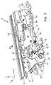
- eine perspektivische Darstellung der Verschlussvorrichtung der Dachkassette, wobei sich ein Verriegelungshaken der Verschlussvorrichtung in seiner hinteren Rastposition in Verriegelungsstellung befindet;
- Fig. 8
- eine Explosionsdarstellung der Verschlussvorrichtung der Fig. 7;
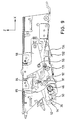
- Fig. 9
- eine Seitenansicht in Richtung auf eine Lagerplatte der Verschlussvorrichtung der Fig. 7;
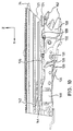
- Fig. 10
- eine Seitenansicht in Richtung auf eine Führungsschiene der Verschlussvorrichtung der Fig. 7;
- Fig. 11
- den schematischen Teilschnitt entlang der Linie XI-XI der Fig. 7, der in Prinzipdarstellung die Riegelsteinankopplungen eines motorisch verschiebbaren Mitnahmegleiters an einen die Bewegung des Verriegelungshakens der Verschlussvorrichtung steuernden Kulissenkörper sowie an einen Dachspitzengleiter des Faltdachs veranschaulicht;
- Fig. 12
- eine perspektivische Darstellung einer abgewandelten Ausführungsform einer Verschlussvorrichtung, wobei sich ein Verriegelungshaken derselben in seiner hinteren Rastposition in Verriegelungsstellung befindet; und
- Fig. 13
- ein Prinzipschaltbild einer Steuerung für das Fahrzeugdach.
- Fig. 1
- a perspective view of a vehicle with a temporarily fixed roof part designed as a roof cassette and a folding roof as an openable roof part, the roof cassette being fixed by means of a locking device to a counter bearing fastened to a B-pillar of the vehicle and the folding roof being in its closed position;
- Fig. 2
- a perspective view of the vehicle of Figure 1 with the folding roof in the open position.
- Fig. 3
- a perspective view of the vehicle of Figure 1, wherein the roof cassette with the folding roof located in the open position is lowered into a storage position.
- Fig. 4
- a perspective view of the vehicle of Figure 1, in which the roof cassette is not shown for reasons of clarity, the removal of side rails is illustrated, which extend between the B-pillars and a front cross member extending above the windshield.
- Fig. 5
- a perspective view of the vehicle of Figure 1 with removed side rails and lowered roof cassette.
- Fig. 6
- a perspective view of the vehicle of Figure 1 with the folding roof closed, wherein an underside of a rear part comprising the rear window of the vehicle is uncoupled from a rear door of the vehicle and pivoted upward, and the rear door of the vehicle is in the open position;
- Fig. 7
- a perspective view of the locking device of the roof cassette, wherein a locking hook of the locking device is in its rear latching position in the locking position;
- Fig. 8
- an exploded view of the closure device of FIG. 7;
- Fig. 9
- a side view towards a bearing plate of the closure device of FIG. 7;
- Fig. 10
- a side view towards a guide rail of the closure device of FIG. 7;
- Fig. 11
- the schematic partial section along the line XI-XI of Figure 7, which illustrates in principle the locking bar couplings of a motor-driven sliding glider to a link body controlling the movement of the locking hook of the locking device and to a rooftop glider of the folding roof;
- Fig. 12
- a perspective view of a modified embodiment of a locking device, wherein a locking hook of the same is in its rear latching position in the locking position; and
- Fig. 13
- a schematic diagram of a controller for the vehicle roof.
In den Fign. 1 bis 6 ist ein Fahrzeug 10 mit einem Fahrzeugdach 1 gezeigt, welches
ein von einem als Elektromotor 222 ausgebildeten Antriebsmotor betätigbares
öffnungsfähiges Dachteil, ein zeitweise feststehendes Dachteil, ein zumindest
zeitweise feststehendes Dachteil, ein Heckteil 6 sowie Seitenholme 28 umfasst.
Dabei ist das öffnungsfähige Dachteil ein Faltdach 30, welches in Führungen des
zeitweise feststehenden Dachteils sowie in solchen der Seitenholme 28 in Öffnungs- bzw.
Schließrichtung 32 verschiebbar aufgenommen und in beliebige
Zwischenstellungen zwischen seiner Öffnungsstellung (vgl. Fign. 2, 3 und 5) und
seiner Schließstellung (siehe Fign. 1 und 6) bringbar ist. In Öffnungsstellung ist das
Faltdach 30 in dem zeitweise feststehenden Dachteil, welches in dem
veranschaulichten Ausführungsbeispiel ein als Dachkassette 12 ausgebildetes
hinteres Dachteil des Fahrzeugdachs 1 ist, gelagert, wobei alle in den Führungen
verschiebbaren Teile des Faltdachs 30 in den in der Dachkassette 12 angeordneten
Führungen aufgenommen und mit Bezug auf die Dachkassette 12 arretierbar sind,
wie dies weiter unten im Zusammenhang mit den Fign. 7 bis 12 näher erläutert wird.
Dabei ist das Faltdach 30 in Öffnungsstellung soweit nach hinten in Öffnungsrichtung
32 verschoben, dass seine Dachspitze 149 im Wesentlichen bündig mit einer
Vorderkante der Dachkassette 12 abschließt.In Figs. 1 to 6, a
Die in der Dachkassette 12 angeordneten Führungen werden von
Führungsschienenabschnitten 22 gebildet, die an Verschlussvorrichtungen 14
angebracht sind, welche ihrerseits an der Dachkassette 12 festgelegt sind, wobei die
Führungsschienenabschnitte 22 mit vorderen Führungsschienenabschnitten 26 in
Fluchtung stehen, wenn die Dachkassette 12 mit Bezug auf das zumindest zeitweise
feststehende Dachteil verriegelt ist. Die vorderen Führungsschienenabschnitte 26
bilden die in den Seitenholmen 28 vorhandenen Führungen und sind schwimmend in
den Seitenholmen 28 aufgenommen. Die Seitenholme 28 sind lösbar mit dem
Fahrzeug 10 verbunden, wozu im Bereich der Stoßstelle zwischen einem vorderen,
oberhalb der Windschutzscheibe verlaufenden Querträger 2 und vorderen seitlichen
Säulen (A-Säulen 3) vordere Seitenholmlager 13 sowie im Bereich des oberen
Endes von ein zumindestens zeitweise feststehendes weiteres Dachteil bildenden
hinteren Säulen (B-Säulen 20) hintere Seitenholmlager 15 vorgesehen sind. Zum
Ausbau der Seitenholme 28 werden, wie dies in Fig. 4 zu erkennen ist, zunächst die
hinteren Seitenholmlager 15 entriegelt, die Seitenholme 28 an ihrem hinteren Ende
in Richtung des Pfeils 8 angehoben und dann in Richtung des Pfeils 9 nach hinten
aus den vorderen Seitenholmlagern 13 herausgezogen. Die ausgebauten
Seitenholme 28 lassen sich im Fahrzeug 10 in entsprechenden
Aufnahmevorrichtungen, beispielsweise in einer Hecktür 5, ablegen.The guides arranged in the
In der Ausführungsform des Fahrzeugdachs 1 nach den Fign. 1 bis 6 bilden die
hinteren seitlichen Säulen, d.h. die B-Säulen 20, das zumindest zeitweise
feststehende Dachteil. Zwischen den starr mit der Fahrzeugkarosserie verbundenen
B-Säulen 20 kann sich in der Art eines Überrollbügels ein hinterer Querträger 4
erstrecken. Alternativ zur starren Anordnung der B-Säulen 20 können diese auch
nach unten absenkbar ausgebildet sein. Je eine Verschlussvorrichtung 14 ist an der
in Fahrtrichtung linken und rechten Seite der Dachkassette 12 angebracht und
wechselwirkt mit einem Gegenlager 11, welches nahe einem oberen Ende jeder der
B-Säulen 20 festgelegt ist, um die über den Elektromotor 222 betätigbare
Verriegelung und Entriegelung der Dachkassette 12 mit Bezug auf die B-Säulen 20
zu bewirken.In the embodiment of the vehicle roof 1 according to FIGS. 1 to 6 form the
rear side pillars, i.e. the B-
Die Betätigung sowohl der Verriegelung und Entriegelung der Dachkassette 12 mit
Bezug auf die Gegenlager 11 als auch die Betätigung der Öffnungs- und
Schließbewegung des Faltdachs 30 wird letztendlich von einem Mitnahmegleiter 114
bewirkt, der über ein drucksteifes Kabel 174 vom dem im mittleren hinteren Bereich
der Dachkassette 12 angeordneten Elektromotor 222 bewegt wird, und dessen
Funktionsweise ausführlich weiter unten insbesondere unter Bezugnahme auf Fig.
11 erläutert wird. The actuation of both the locking and unlocking of the
Das Heckteil 6 des Fahrzeugdachs 1 ist an der Dachkassette 12 festgelegt und
umfasst eine Heckscheibe 18 aus faltbarem Kunststoffmaterial sowie ebenfalls
faltbare Seitenteile 16. Die Dachkassette 12 ist über eine nicht gezeigte
Viergelenkanordnung mit der Fahrzeugkarosserie verbunden und nach Entriegelung
von dem Gegenlager 11 der B-Säulen 20 soweit absenkbar, dass eine Oberseite der
Dachkassette 12 im Wesentlichen auf der Höhe der Fahrzeuggürtellinie zu liegen
kommt. Um die Dachkassette 12 in abgesenkter Position zu arretieren, ist an der
Viergelenkanordnung selbst ebenfalls ein Gegenlager vorgesehen, mit dem die
Verschlussvorrichtung 14 in ähnlicher Weise wie mit dem Gegenlager 11
wechselwirkt. Eine Unterseite 7 des Heckteils 6 ist an eine Hecktür 5 anlegbar und
kann, wie dies in Fig. 6 gezeigt ist, nach oben geklappt werden, um den Zugang zu
einem im Fahrzeugheck gelegenen Stauraum zu verbessern. Die Hecktür 5
ihrerseits ist mit ihrer Unterseite schwenkbar mit der Fahrzeugkarosserie verbunden
und kann unabhängig von der Position, welche die Unterseite 7 des Heckteils 6
einnimmt sowie auch bei abgesenkter Dachkassette 12 nach hinten geklappt
werden. Zur Erhöhung der Stabilität des Heckteils und zur Anbringung einer
Schlossfalle für die Hecktür 5 kann an der Unterseite 7 des Heckteils 6 ein
Querträger angeordnet sein.The rear part 6 of the vehicle roof 1 is fixed to the
Nachfolgend werden anhand der Fign. 7 bis 12 zwei Ausführungsbeispiele der
Verschlussvorrichtung 14 detailliert beschrieben, wobei an der Dachkassette 12 zwei
spiegelbildlich ausgeführte Verschlussvorrichtungen angebracht sind, jedoch nur die
in Fahrtrichtung gesehen linke Verschlussvorrichtung 14 in den Figuren
wiedergegeben ist. Alle Ausführungen hinsichtlich der linken Verschlussvorrichtung
14 beziehen sich sinngemäß auch auf die spiegelbildliche rechte
Verschlussvorrichtung. Es sei ferner angemerkt, dass die in Fign. 7 bis 11 mit X
bezeichnete Achse in Öffnungsrichtung des Faltdachs 30, d.h., in die gleiche
Richtung wie der auf das Fahrzeug heck gerichtete Pfeil 32 in Fig. 2 weist.In the following, using FIGS. 7 to 12 two embodiments of the
Die beiden Verschlussvorrichtungen sind symmetrisch zu einer in
Fahrzeuglängsrichtung verlaufenden Symmetrieachse im Inneren der Dachkassette
12 nahe deren seitlichen Außenflächen dergestalt montiert, dass sie an den an den
B-Säulen 20 angebrachten Gegenlagern 11 festgelegt werden können, wobei
gleichzeitig die Führungsschienenabschnitte 22 der Verschlussvorrichtungen 14 mit
den vorderen Führungsschienenabschnitten 26 der Seitenholme 20 fluchtend
ausgerichtet werden, indem eine am Führungsschienenabschnitt 22 festgelegte
Ausrichtleiste 24 als Ausrichtorgan in Eingriff mit den vorderen
Führungsschienenabschnitten 26 gebracht wird.The two closure devices are symmetrical to one in
Vehicle longitudinal axis of symmetry inside the
Die Verschlussvorrichtung 14 umfasst eine Lagerplatte 34 mit einem als
Aufnahmenut 48 ausgebildeten Aufnahmeorgan, in welches ein Bolzen 46 des an
der B-Säule 20 angebrachten Gegenlagers 11 in Verschieberichtung 50 (vgl. Fig. 9)
eingeführt und mittels einer Verriegelungsnut 42 eines Verriegelungshakens 36
verriegelt werden kann. Dabei ist die Verriegelungsnut 42 in einem vorderen Arm 38
des Verriegelungshakens 36 plaziert, der über einen Lagerstift 56 schwenkbar in
einem geknickten Lagerhebel 58 aufgenommen ist. Der Lagerstift 56 des
Verriegelungshakens 36 ist etwa mittig zwischen dem die Verriegelungsnut 42
umfassenden vorderen Arm 38 und einem hinteren Arm 40 angeordnet, wobei der
Verriegelungshaken 36 um die Achse des Lagerstifts 56 in Schwenkrichtung 44
(siehe Fig. 7) zwischen einer in den Fign. 7, 9 und 10 dargestellten Verriegelungs- und
einer Freigabestellung schwenkbar ist, In Verriegelungsstellung ist der
Verriegelungshaken 36 ferner zwischen einer in Fig. 9 in unterbrochenen Linien
wiedergegebenen vorderen Rastposition 52 und einer hinteren Rastposition 54 in
Verschieberichtung 50 verschiebbar.The
Der Lagerhebel 58 ist zweiteilig ausgebildet und umfasst zwei in Y-Richtung um die
Dicke einer Buchse 62 beabstandete deckungsgleiche Hälften, deren Abstand so
bemessen ist, dass der Verriegelungshaken 36 sowie ein weiter unten beschriebener
Steuerhebel 84 zwischen ihnen aufgenommen werden kann. Die Buchse 62 ist auf
eine Achse 60 aufgeschoben, die einen Arm 64 des Lagerhebels 58 dergestalt in Y-Richtung
durchsetzt, dass sie die Hälften des Lagerhebels 58 beidseitig überragt und
zum einen in der Lagerplatte 34 und zum anderen in einem den Arm 64
umgreifenden Lagerbügel 59 gehalten ist, welcher seinerseits an der Lagerplatte 34
festgelegt ist. Der Lagerhebel 58 ist mittels eines an seinem zweiten Arm 66
festgelegten Steuerstifts 68 um die Achse 60 schwenkbar, wobei der Steuerstift 68
den Lagerhebel in Y-Richtung überragt und in eine Steuerbahn 72 einer
Schaltkulisse 74 eingreift, in der er über einen Gleitstein 70 geführt ist.The bearing
Die Schaltkulisse 74 ist in einem Kulissenkörper 80 integriert, der eine zweite
Schaltkulisse 78 aufweist, in deren Steuerbahn 76 ein an dem Steuerhebel 84
festgelegter Steuerbolzen 82 verschiebbar aufgenommen ist und dessen
Schwenkbewegung um die Achse des Lagerstifts 56 bewirkt, mittels dem der
Steuerhebel 84 gemeinsam mit dem Verriegelungshaken 36 in dem Lagerhebel 58
gelagert ist, wobei sich der Steuerhebel in Richtung auf den vorderen Arm 38 des
Verriegelungshakens 36 erstreckt. Eine Abkantung 92 des Steuerhebels 84 greift in
eine in -Z-Richtung offene Ausnehmung 85 des Verriegelungshakens 36 ein und
dient der Mitnahme des Verriegelungshakens 36, wenn der Steuerhebel 84 über
seinen Steuerbolzen 82 von der Steuerbahn 78 im Uhrzeigersinn geschwenkt wird
(die vorliegend verwendeten Begriffe Uhrzeigersinn und Gegenuhrzeigersinn
beziehen sich jeweils auf eine Betrachtung in Y-Richtung).The switching
Ein Haltehebel 89 ist etwa mittig durch einen Ansatzbolzen 91 schwenkbar auf dem
Verriegelungshaken 36 im Bereich zwischen der Ausnehmung 85 und der
Verriegelungsnut 42 gelagert, wobei eine Zugfeder 90 zwischen einem an einem
ersten Arm 93 des Haltehebels 89 befindlichen Vorsprung 88 und einer Abkantung
86 des Steuerhebels 84 vorgesehen ist. Mittels der Zugfeder 90 wird dem
Steuerhebel 84 eine Vorspannung im Uhrzeigersinn dergestalt aufgeprägt, dass die
Abkantung 92 des Steuerhebels 84 spielfrei in der Ausnehmung 85 des
Verriegelungshakens 36 anliegt, wobei gleichzeitig der Haltehebel 89 ebenfalls im
Uhrzeigersinn geschwenkt wird und dieser mittels einer an seinem ersten Arm 93
vorgesehenen Schrägfläche 95 vorgespannt an einem sich in -Y-Richtung
erstreckenden, an der Lagerplatte 34 festgelegten Haltebolzen 87 anliegt, sofern
sich der Verriegelungshaken 36 außerhalb seiner Freigabestellung befindet. Die im
ersten Arm 93 des Haltehebels 89 oberhalb eines im Wesentlichen in X-Richtung
geöffneten Rastbereichs 98 angeordnete Schrägfläche 95 ist so ausgebildet, dass
über die vorgespannte Anlage der Schrägfläche 95 an dem Haltebolzen 87 eine
Kraft auf den Verriegelungshaken 36 ausgeübt wird, die letzteren im
Gegenuhrzeigersinn um die Achse des Lagerstifts 56 dreht, und der
Verriegelungshaken 36 über eine sich in Längsrichtung des Fahrzeugs 10 gesehen
hinter der Verriegelungsnut 42 liegende (d.h., ausgehend von der Verriegelungsnut
42 in positiver X-Richtung versetzt angeordnete), in Verschieberichtung 50
verlaufende Gleitfläche 190 auf einer Abkantung 188 der Lagerplatte 34 aufliegt. Der
Haltebolzen 87 dient ferner als Fangvorrichtung, in die der Rastbereich 98 des
Haltehebels 89 eingreift, wenn der Verriegelungshaken 36 sich in seiner
Freigabestellung befindet.A holding
Ein zweiter Arm 94 des Haltehebels 89, der sich unterhalb des Ansatzbolzens 91
(d.h., mit Bezug auf diesen in negativer Z-Richtung versetzt) befindet, weist einen im
Wesentlichen in X-Richtung überstehenden Vorsprung 97 auf, der, um den
Steuerhebel 84 mit Bezug auf den Verriegelungshaken 36 festzulegen, an eine
Unterseite der Abkantung 92 des Steuerhebels 84 anlegbar ist, sobald sich der
Verriegelungshaken 36 seiner hinteren Rastposition 54 nähert.A second arm 94 of the holding
Eine insgesamt mit 100 bezeichnete, sich im Wesentlichen in X-Richtung
erstreckende Ausrichtplatte ist mit der Lagerplatte 34 über mehrere Schrauben 99
verbunden, die gleichzeitig einen unteren Bereich des Führungsschienenabschnitts
22 durchsetzten, der überdies über nicht dargestellte Blindniete in seinem oberen
Bereich direkt an der Lagerplatte 34 festgelegt ist, wobei ein fester Zusammenhalt
von Lagerplatte 34, Führungsschienenabschnitt 22 und Ausrichtplatte 100 erzielt
wird. Der Führungsschienenabschnitt 22 weist eine untere und eine obere Gleitbahn
101 bzw. 102 auf, die durch eine in der X-Z-Ebene verlaufende Trennwand 104
voneinander getrennt sind. Die untere Gleitbahn 101 ist seitlich von der Trennwand
104 und einer Rückwand der Lagerplatte 34 sowie nach oben und unten durch
Schenkel, die sich ausgehend von der Trennwand 104 in -Y-Richtung erstrecken,
begrenzt und in +/-X-Richtung offen. Sie dient der in +/-X-Richtung verschieblichen
Aufnahme des Kulsissenkörpers 80, der seinerseits eine in Y-Richtung überstehende
Anlaufkante 108 aufweist, die durch einen Durchbruch 106 in der Trennwand 104 in
den Bereich der Gleitbahn 102 hineinreicht. Dabei ist der Kulissenkörper 80 in +/-X-Richtung
zwischen einer hinteren und einer vorderen Endlage verschiebbar.A total of 100, essentially in the X direction
extending alignment plate is with the bearing
Die Gleitbahn 102 ist nach oben und unten durch sich in Y-Richtung erstreckende
Schenkel 112 bzw. 110 begrenzt und mittels senkrecht auf den Schenkeln 110 und
112 angeordneter Stege 109 in wenigstens zwei offene Kammern 111, 113 unterteilt,
von denen die innere Kammer 111 der Aufnahme eines Mitnahmegleiters 114 und
die äußere Kammer 113 der Aufnahme eines Dachspitzengleiters 116 dient. Beide
Gleiter 114 und 116 sind in +/-X-Richtung verschiebbar, wobei am Mitnahmegleiter
114 das drucksteife Kabel 174 angebracht ist, welches über den an der
Dachkassette 12 festgelegten Elektromotor 222 (siehe Fig. 2) bewegbar ist und in
einem Kabelkanal 118 geführt wird, der seitlich neben der Gleitbahn 102 in der
Trennwand 104 aufgenommen ist.The
Zwischen einer Oberseite 119 der Ausrichtplatte 100 und einer Unterseite des
Schenkels 110 ist ein in +/-X-Richtung verschiebbarer Tastgleiter 120 als Teil einer
Gegenlagererkennungseinrichtung aufgenommen, der durch Wirkung einer zwischen
dem Tastgleiter 120 und der Ausrichtplatte 100 angebrachten Zugfeder 122 in -X-Richtung
dergestalt vorgespannt wird, dass seine Tastspitze 124 eine Vorderkante
125 des Führungsschienenabschnitts 22 überragt. An dem der Tastspitze 124 in X-Richtung
gesehen gegenüberliegenden Ende des Tastgleiters 120 ist ein Ausrücker
126 angeordnet, der mit einem Ausrückarm 128 eines geknickten Sperrhebels 130
wechselwirkt, der seinerseits um eine Achse 131 schwenkbar zwischen der
Lagerplatte 34 und der Ausrichtplatte 100 gelagert ist. An einem sich im
Wesentlichen senkrecht zu dem Ausrückarm 128 erstreckenden Arm 132 des
Sperrhebels 130 ist eine Sperrnase 133 vorgesehen, die ausgelegt ist, in eine
komplementär geformte, nicht dargestellte Anlaufkante an der Unterseite des
Kulissenkörpers 80 einzugreifen, wenn sich der Kulissenkörper 80 in einer hinter
seiner vorderen Endlage befindlichen Warnposition aufhält. Dabei ist die
Warnposition des Kulissenkörpers 80 mit Bezug auf die Lagerplatte 34 an einer
Stelle angeordnet, die sich zwischen der vorderen und der hinteren Endlage des
Kulissenkörpers 80 befindet, wobei die vordere Endlage einer kleineren X-Koordinate
entspricht als die hintere Endlage.Between a top 119 of the
Der Sperrhebel 130 wird mittels eines Federarms 134 einer zwei Federarme 134 und
136 umfassenden Kombifeder 138 im Gegenuhrzeigersinn belastet, so dass die
Sperrnase 133 bei sich in Warnposition befindlichem Kulissenkörper 80 vorgespannt
an dessen Anlaufkante anliegt und verhindert, dass der Kulissenkörper 80 seine
vordere Endlage erreicht, falls sich das Gegenlager 11 nicht in seiner Solllage mit
Bezug auf die Verschlussvorrichtung 14 befindet. Der Kulissenkörper ist in diesem
Fall nur zwischen seiner hinteren Endlage und seiner Warnposition verschiebbar.
Wird hingegen beim Ankopplungsvorgang der Verschlussvorrichtung 14 an das
Gegenlager 11 die Solllage des Gegenlagers 11 relativ zur Verschlussvorrichtung 14
erreicht, kommt die Tastspitze 124 des Tastgleiters 120 an dem Gegenlager 11 zur
Anlage, der Tastgleiter 120 wird in X-Richtung entgegen der Kraft der Zugfeder 122
so weit verschoben, dass der Ausrücker 126 den Ausrückarm 128 des Sperrhebels
130 betätigt und letzteren um die Achse 131 im Uhrzeigersinn entgegen der Wirkung
des Federarms 134 schwenkt, und die Sperrnase 133 des Sperrhebels 130 gelangt
außer Eingriff mit Bezug auf die Anlaufkante an der Unterseite des Kulissenkörpers
80. Der Kulissenkörper 80 ist nun weiter nach vorne (also in -X-Richtung) in
Richtung auf seine vordere Endlage verschiebbar. Der zweite Federarm 136 der
Kombifeder 138 ist nach oben in Z-Richtung vorgespannt und kann entgegen seiner
Vorspannung von dem hinteren Arm 40 des Verriegelungshakens 36 nach unten
ausgelenkt werden, wenn sich der Verriegelungshaken 36 in seiner Freigabestellung
befindet. Dabei wird vom Federarm 136 in seiner nach oben vorgespannten
Grundstellung ein elektrischer Mikroschalter 140 betätigt, der gemeinsam mit der
Kombifeder 138 an der Lagerplatte 34 festgelegt ist, wobei der Mikroschalter 140 ein
entsprechendes Signal "Verriegelungshaken in Verriegelungsstellung" liefert. Dieses
Signal wird als Eingangsgröße in eine die motorische Betätigung der
Verschlussvorrichtung 14 steuernde elektronische Steuerung 218 (vgl. Fig. 13)
eingespeist, die ebenfalls die Steuerung der motorischen Betätigung der Öffnungs- und
Schließbewegung des Faltdachs 30 übernimmt.The locking
Es kann ferner vorgesehen sein, den Federarm 136 anstelle seiner federnden
Vorspannung nach oben formschlüssig mit dem hinteren Arm 40 des
Verriegelungshakens 36 zu verbinden, so dass letzterer den Federarm 136 in beide
Richtungen, d.h., nach oben und unten, betätigt.It can also be provided that the
Alternativ zur Wechselwirkung der Tastspitze 124 des Tastgleiters 120 mit dem
Gegenlager kann auch eine Wechselwirkung der Tastspitze 124 mit dem Seitenholm
28 vorgesehen sein, wobei dann, wenn der Seitenholm 28 sich in Solllage befindet
und er insbesondere mit dem Fahrzeug verriegelt ist, der Tastgleiter 120 beim
Ankopplungsvorgang der Verschlussvorrichtung 14 an das Gegenlager vom
Seitenholm 28 betätigt und in X-Richtung so weit verschoben wird, dass die
Sperrnase 133 des Sperrhebels 130 den Kulissenkörper 80 nicht mehr in seiner
Warnposition arretiert. Ist der Seitenholm 28 hingegen vom Fahrzeug abgenommen
oder befindet er sich aus einem anderen Grund nicht in seiner Solllage mit Bezug auf
die Verschlusseinrichtung 14 in Ankoppelstellung, wird die Tastspitze 124 beim
Ankoppelvorgang nicht oder nicht weit genug in X-Richtung betätigt und der
Kulissenkörper 80 bei Erreichen seiner Warnposition arretiert, auch wenn sich das
Gegenlager in Solllage befindet. Somit wird die Gegenlagererkennungseinrichtung
im Prinzip zur Seitenholmerkennung verwendet. Dies hat den weiteren Vorteil, dass
bei Ankopplung der Verschlussvorrichtung 14 an das weitere Gegenlager, welches
am Viergelenk angebracht ist, der Kulissenkörper 80 nicht weiter als bis in seine
Warnposition verschoben werden kann, da sich zwar das am Viergelenk
vorgesehene Gegenlager in Solllage befindet, ein Seitenholm aber nicht vorhanden
ist. Somit wird verhindert, dass die weiter unten beschriebene Arretierung des
Dachspitzengleiters 116 mit Bezug auf die Verschlusseinrichtung 14 gelöst wird,
wenn die Verschlussvorrichtung 14 am Gegenlager des Viergelenks angekoppelt
wird.As an alternative to the interaction of the
Eine Ausrichtgabel 152 an einem vorderen Ende der Ausrichtplatte 100 dient der
Ausrichtung der Verschlussvorrichtung 14 in Y- und Z-Richtung mit Bezug auf den
vorderen Führungsschienenabschnitt 26, zu welchem Zweck die Ausrichtgabel 152
in ein komplementär geformtes Ausrichtlager eingreift, welches eine Einheit mit dem
schwimmend im Seitenholm 28 gelagerten vorderen Führungsschienenabschnitt 26
bildet. Die am Führungsschienenabschnitt 22 der Verschlussvorrichtung 14
festgelegte Ausrichtleiste 24, die sich in Z-Richtung oberhalb der Ausrichtgabel 152
befindet und in Eingriff mit dem vorderen Führungsschienenabschnitt 26 gebracht
werden kann, verhindert eine Verkippung um die X-Achse des vorderen
Führungsschienenabschnitts 26 mit Bezug auf den Führungsschienenabschnitt 22.
Eine Ausrichtfläche 150 ist an einer Seitenfläche der Ausrichtgabel 152 in der X-Z-Ebene
gelegen und an die Stirnfläche des Bolzens 46 des an der B-Säule 20
angebrachten Gegenlagers 11 anlegbar, so dass im Zusammenwirken mit der
spiegelbildlichen rechten Verschlussvorrichtung und dem rechten Bolzen eine in Y-Richtung
gesehen symmetrische Ausrichtung der gesamten Dachkassette 12 mit
Bezug auf die beiden Bolzen 46 der Gegenlager 11 erfolgt. An
An einer in Y-Richtung verlaufenden Abkantung der Ausrichtplatte 100 ist eine
Endlagenfeder 146 festgelegt, die zwei Federarme 142 und 144 umfasst, von denen
der Federarm 142 von unten in die Kammer 113 eingreift, in der der
Dachspitzengleiter 116 aufgenommen ist, welcher mit einer Dachspitze 149 des
Faltdachs 30 verbunden ist und die Öffnungs- und Schließbewegung desselben
bewirkt. Der zweite Federarm 144 ist ausgelegt, einen elektrischen Mikroschalter 148
mechanisch zu betätigen, wenn sich der Dachspitzengleiter 116 in einer
Halteposition befindet, wobei der Mikroschalter 148 das Signal "Dachspitzengleiter in
Halteposition" an die elektronische Steuerung 218 gibt (siehe Fig. 13). In dieser
Position ist der Dachspitzengleiter 116 vollständig in dem
Führungsschienenabschnitt 22 der Verschlussvorrichtung 14 aufgenommen und
lässt sich mit Bezug auf den Führungsschienenabschnitt 22 arretieren. Mit dem
Dachspitzengliter 116 sind sämtliche verschiebbaren Teile des Faltdachs 30 in dem
Führungsschienenabschnitt 22 gehalten und können mitsamt der Dachkassette 12
von dem Gegenlager 11 abgekoppelt werden.On a bend of the
Wie aus Fig. 13 ersichtlich wird, erhält die Steuerung 218 für das Fahrzeugdach
neben den Signalen eines zwei Schaltpositionen ("Öffnen" und "Schließen")
aufweisenden Betätigungsschalters 224 auch die Signale zweier Sensoren 226 und
228 als Eingangsgrößen. Der Betätigungsschalter 224 ist vom Bediener bedienbar
und dient der Einleitung sowohl der Öffnungs- und Schließbewegung des Faltdachs
als auch der An- und Abkopplungsbewegung der Verschlussvorrichtung, wobei über
die Schwenk- und Verschiebebewegungen des Verriegelungshakens die
Verriegelung und Entriegelung der Dachkassette 12 mit Bezug auf die Gegenlager
11 an der B-Säulen 20 bewirkt wird. Alternativ zu dem einen Betätigungsschalter 224
können zwei Betätigungsschalter vorgesehen sein, von denen einer die Öffnungs- und
Schließbewegung des Faltdachs und einer bei vollständig geöffnetem Faltdach
die An- und Abkopplungsbewegung der Verschlussvorrichtung einleitet. Bei den
beiden Sensoren 226 und 228 handelt es sich im Fall der ersten Ausführungsform
der Verschlussvorrichtung (dargestellt in den Fign. 7 bis 11) um die Mikroschalter
148 bzw. 140. Bei der weiter unten im Zusammenhang mit Fig. 12 beschriebenen
zweiten Ausführungsform der Verschlussvorrichtung wird als Sensor 228 anstelle
des Mikroschalters 140 ein induktiver Sensor 216 eingesetzt.As can be seen from FIG. 13, the
Bei geschlossenem Faltdach 30 befinden sich der Dachspitzengleiter 116 und der
Mitnahmegleiter 114 in dem vorderen Führungsschienenabschnitt 26 und sind
mittels eines Riegelsteins 164 formschlüssig miteinander verbunden, der in Z-Richtung
verschiebbar im Dachspitzengleiter 116 aufgenommen ist. Die
Dachkassette 12 ist über die Verschlussvorrichtungen 14 an den B-Säulen 20 des
Fahrzeugs 10 festgelegt, wobei sich der Verriegelungshaken 36 in
Verriegelungsstellung in seiner hinteren Rastposition 54 aufhält. Der Kulissenkörper
80 steht in seiner vorderen Endlage und ist in dieser durch einen in Y-Richtung
verschiebbar gelagerten Riegelstein 156, der mittels einer über eine Druckfeder 160
belasteten Kugel 158 in seinen Endlagen einrastbar ist, in einer Aussparung 162 der
Lagerplatte 34 gehalten. Während der die Schwenkbewegung des Lagerhebels 58
und damit die Verschiebebewegung des Verriegelungshakens 36 steuernde
Steuerstift 68 mit dem Gleitstein 70 am hinteren Ende eines Haltebereichs 204 der
Steuerbahn 72 der Schaltkulisse 74 steht, befindet sich der Steuerbolzen 82 des
Steuerhebels 84 in einem Haltebereich 206 der Steuerbahn 76 der für die
Schwenkbewegung des Verriegelungshakens 36 zuständigen Schaltkulisse 78. Der
Haltehebel 89 ist durch Anlage seiner Schrägfläche 95 an dem Haltebolzen 87
soweit im Gegenuhrzeigersinn geschwenkt, dass sein Vorsprung 97 die Abkantung
92 des Steuerhebels 84 untergreift und diesen mit Bezug auf den
Verriegelungshaken 36 festlegt. Da die Position des Steuerhebels 84 seinerseits
durch seine Aufnahme sowohl im Lagerhebel 58 (durch den Lagerstift 56) als auch
im Haltebereich 206 der Schalkulisse 78 (durch den Steuerbolzen 82) fest
vorgegeben ist, ist der Verriegelungshaken 36 letztendlich in seiner
Verriegelungsposition blockiert. Damit sich der Kulissenköper 80 in seiner vorderen
Endlage befinden kann, muss selbstverständlich wie oben beschrieben das
Gegenlager 11 bzw. der Seitenholm 28 in Solllage stehen, der Tastgleiter 120
betätigt und die Sperrnase 133 des Sperrhebels 130 außer Eingriff mit Bezug auf die
an der Unterseite des Kulissenkörpers 80 angeordnete Anlaufkante sein. When the
Um die Dachkassette 12 von der B-Säule 20 abzukoppeln, muss zunächst durch
Betätigung der Schaltposition "Öffnen" des Betätigungsschalter 224 das Faltdach 30
geöffnet werden, indem der Dachspitzengleiter 116 in Öffnungsrichtung 32 nach
hinten verschoben wird. Die Verschiebebewegung wird dem Dachspitzengleiter 116
vom Mitnahmegleiter 114 aufgeprägt, der seinerseits mittels der an sich bekannten
drucksteifen Kabel 174 über den Elektromotor 222 bewegt wird, der in der
Dachkassette 12 aufgenommen ist. Sowohl der Dachspitzengleiter 116 als auch der
Mitnahmegleiter 114 gelangen schließlich von dem vorderen
Führungsschienenabschnitt 26 in den Führungsschienenabschnitt 22 der
Verschlussvorrichtung 14, wobei der Dachspitzengleiter 116, sobald er in seiner
Halteposition angelangt ist, an einen Anschlag 168 anstößt, der in dem
Führungsschienenabschnitt 22 vorgesehen ist und eine weitere Verschiebung des
Dachspitzengleiters 116 nach hinten (in X-Richtung) verhindert (siehe Fig. 11), wobei
auch, wie oben beschrieben, der elektrische Mikroschalter 148 vom Federarm 144
betätigt wird. Der Mitnahmegleiter 114 hat jetzt seine in Fig. 11 wiedergegebene
Übergabeposition erreicht. Betätigt der Bediener weiterhin die Schaltposition
"Öffnen" des Betätigungsschalters 224, so wird bei an der Steuerung 218
anliegendem Signal "Dachspitzengleiter in Halteposition" des Mikroschalters 148 die
Abkopplungsbewegung der Verschlussvorrichtung eingeleitet, und zwar
vorzugsweise erst, nachdem bestimmte Sicherheitsbedingungen erfüllt sind. Hierzu
kann z.B. zählen, dass das Fahrzeug nicht bewegt werden darf und/oder dass der
Bediener den Betätigungsschalter 224 während einer vorbestimmten Betätigungszeit
in der Schaltposition "Öffnen" halten muss.In order to uncouple the
Bei Einleitung des Abkopplungsvorgangs wird zunächst der Mitnahmegleiter 114
vom Elektromotor 222 über das drucksteife Kabel 174 mit einer Kraft in X-Richtung
beaufschlagt, so dass eine Schrägfläche 170 in einer den Riegelstein 164
aufnehmenden Aussparung 166 in dem Mitnahmegleiter 114 eine Kraft in Z-Richtung
auf den Riegelstein 164 ausübt, die ausreicht, letzteren in Z-Richtung so weit zu
verschieben, dass der Riegelstein 164 außer Eingriff mit Bezug auf die Aussparung
166 in dem Mitnahmegleiter 114 gelangt und mit seinem dem Mitnahmegleiter 114
abgewandten Ende in eine Aussparung 172 in dem Führungsschienenabschnitt 22
geschoben wird. Damit ist der Dachspitzengleiter 116 formschlüssig in dem
Führungsschienenabschnitt gehalten, und der Mitnahmegleiter 114 für eine weitere
Verschiebung in X-Richtung freigegeben, wobei die dem Dachspitzengleiter 116
zugewandte Seite des Mitnahmegleiters 114 so ausgebildet ist, dass ein Lösen der
Formschlussverbindung zwischen dem Dachspitzengleiter 116 und dem
Führungsschienenabschnitt 22 durch eine Verschiebung des Riegelsteins 164 im
Dachspitzengleiter 116 in -Z-Richtung ausgeschlossen ist. Nach Durchlaufen einer
vorbestimmten Wegstrecke kommt der Mitnahmegleiter 114 mittels seiner
Koppelfläche 176 an der Anlaufkante 108 des sich in der vorderen Endlage gemäß
Fig. 11 befindlichen Kulissenkörpers 80 zur Anlage, wobei gleichzeitig eine
komplementär zum Riegelstein 156 geformte Aussparung 180 in der dem
Kulissenkörper 80 zugewandten Seite des Mitnahmegleiters 114 so zu liegen
kommt, dass bei weiterer Kraftausübung in X-Richtung auf den Mitnahmegleiter 114
dieser den Kulissenkörper 80 über die an der Anlaufkante 108 anliegende
Koppelfläche 176 mitnimmt, wobei eine Schrägfläche 178 in der den Riegelstein 156
aufnehmenden Aussparung 162 in der Lagerplatte 34 eine Kraft in Y-Richtung auf
den Riegelstein 156 ausübt, die den Riegelstein 156 in dem Kulissenkörper 80 in
seine zweite Endlage verschiebt, in der der Riegelstein 156 außer Eingriff mit Bezug
zur Aussparung 162 und in Eingriff mit Bezug zur Aussparung 180 steht. Der
Riegelstein 156 löst die Formschlussverbindung des Kulissenkörpers 80 mit der
Lagerplatte 34 und bildet zur gleichen Zeit eine solche zwischen dem Kulissenkörper
80 und dem Mitnahmegleiter 114, der den Kulissenkörper 80 in Richtung auf dessen
hintere Endlage mitnimmt. Dabei ist eine Verschiebung des Riegelsteins 156 in -Y-Richtung
aus der Aussparung 180 heraus nicht nur aufgrund der federbelasteten
Kugel 158 ausgeschlossen, die den Riegelstein 156 in seiner Endlage hält, sondern
auch dadurch, dass die dem Mitnahmegleiter 114 zugewandte Seite der Lagerplatte
34 hinter der Schrägfläche 178 entsprechend nahe an den Kulissenkörper 80
herangeführt ist.When the uncoupling process is initiated, the
Bei Verschiebung des Kulissenkörpers 80 in X-Richtung auf seine hintere Endlage
hin, gelangt der Gleitstein 70, der auf dem Steuerstift 68 des Lagerhebels 58
aufgenommen ist, zunächst von dem Haltebereich 204 in einen rampenförmig nach
unten verlaufenden Verschiebebereich 208 der Steuerbahn 72. Hierbei wird dem
Lagerhebel 58 um dessen Achse 60 eine Schwenkbewegung im Uhrzeigersinn
aufgezwungen, die über den Lagerstift 56 in eine Verschiebebewegung des
Verriegelungshakens 36 umgeformt wird, wobei der Verriegelungshaken 36 von
seiner hinteren Rastposition 54 in Verschieberichtung 50 nach vorne in -X-Richtung
auf seine vordere Rastposition 52 hin verschoben wird und über seine Gleitfläche
190 auf der Abkantung 188 der Lagerplatte 34 gleitet. Die vordere Rastposition 52 ist
erreicht, wenn sich der Gleitstein 70 in der tiefsten Stelle des rampenförmigen
Verschiebebereichs 208 der Steuerbahn befindet und in einen vorderen Haltebereich
212 übergeht, in dem er im Wesentlichen horizontal geführt wird, so dass der
Lagerhebel 58 keine Schwenkbewegung mehr durchführt.When sliding the
Etwa bei Erreichen der vorderen Rastposition 52 wird durch weitere Verschiebung
des Kulissenkörpers 80 in X-Richtung die Schwenkbewegung des
Verriegelungshakens 36 von seiner Verriegelungs- in seine Freigabestellung
eingeleitet, indem der Steuerbolzen 82 des Steuerhebels 84 den Haltebereich 206
der Steuerbahn 76 verlässt und auf einen aufwärts gerichteten Bereich einer
Schwenknocke 210 trifft, die die Steuerbahn 76 im vorderen Bereich in der Form
eines liegenden Y aufteilt. Der Steuerbolzen 82 folgt dem oberen Schenkel des
liegenden Y und prägt über die Abkantung 92 dem Verriegelungshaken 36 eine
Schwenkbewegung um die Achse des Lagerstifts 56 auf, der auch den Steuerhebel
84 schwenkbar mit dem Lagerhebel 58 verbindet. Sobald der Verriegelungshaken 36
in die Freigabestellung angehoben ist, rastet der Rastbereich 98 des Haltehebels 89
in den Haltebolzen 87 ein und hält den Verriegelungshaken 36 in seiner
Freigabestellung. Dabei wird über den Federarm 136 die Betätigung des
Mikroschalters 140 aufgehoben und der Bolzen 46 des Gegenlagers 11 kommt aus
der Verriegelungsnut 42 des Verriegelungshakens 36 frei, so dass die Dachkassette
12 von der B-Säule 20 abgekoppelt ist und, wie bereits im Zusammenhang mit den
Fign. 1 bis 6 beschrieben wurde, abgesenkt werden kann.Approximately when the
Der Ankopplungsvorgang der Dachkassette 12 mittels der Verschlussvorrichtung 14
am Gegenlager 11 verläuft sinngemäß in umgekehrter Reihenfolge, wobei auf
folgende Besonderheiten hingewiesen werden soll: Befindet sich der Kulissenkörper
80 in seiner hinteren Endlage, steht der Steuerbolzen 82 vor der Vorderkante der
Schwenknocke 210. Wird die Verschlussvorrichtung 14 manuell gegen das
Gegenlager 11 gedrückt, stößt zunächst der Bolzen 46 von vorne gegen den in die
Aufnahmenut 48 hineinragenden zweiten Arm 94 des Haltehebels 89, wodurch
diesem eine Schwenkbewegung gegen den Uhrzeigersinn aufgezwungen wird und
gleichzeitig der Bolzen 46 beim Auftreffen auf die Rückwand der Verriegelungsnut 42
auf den Verriegelungshaken 36 eine Kraft ausübt, deren Wirkungslinie unterhalb des
Lagerstifts 56 verläuft, so dass dem Verriegelungshaken 36 ein Drehmoment im
Gegenuhrzeigersinn aufgeprägt wird. Auf diese Weise kommt der Rastbereich 98
des Haltehebels 89 vom Haltebolzen 87 frei, und der Verriegelungshaken 36 kann in
seine Verriegelungsstellung schwenken, ohne dass der Steuerbolzen 82 diese
Schwenkbewegung behindert, da er außerhalb der Steuerbahn 76 steht. Sobald die
Schrägfläche 95 des Haltehebels 89 an dem Haltebolzen anliegt, wird der
Verriegelungshaken 36, wie bereits beschrieben, durch die Zugfeder 90 in Richtung
auf die Verriegelungsstellung vorgespannt. Hat der Verriegelungshaken 36 seine
Verriegelungsstellung erreicht, wird der Mikroschalter 140 betätigt und liefert als
Sensor 228 der Steuerung 218 das Eingangssignal "Verriegelungshaken in
Verriegelungsstellung". Nach Ablauf einer vorbestimmten Totzeit, beispielsweise
nach Ablauf von 5 Sekunden, löst die Steuerung 218 die automatische
Zuziehbewegung des Verriegelungshakens 36 aus, indem sie den Elektromotor 222
ansteuert, der seinerseits die Verschiebung des Kulissenkörpers 80 nach vorn in
Richtung auf seine vordere Endlage betätigt.The coupling process of the
Bei Bewegung des Kulissenkörpers 80 nach vorne (in -X-Richtung) wird der
Steuerbolzen 82 des Steuerhebels 84 durch die Schwenknocke 210 nach unten
ausgelenkt und in den unteren Arm des liegenden Y eingeführt. Diese Bewegung
wird nicht auf den Verriegelungshaken 36 übertragen, da die Abkantung 92 des
Steuerhebels 84 noch nicht von dem Vorsprung 97 des Haltehebels 89 untergriffen
wird, sondern vielmehr nach unten aus der Ausnehmung 85 des
Verriegelungshakens 36 auswandern kann. Erst wenn der Verriegelungshaken 36
weiter in Richtung auf seine hintere Rastposition 54 verschoben wird, ist der
Haltehebel 89 soweit im Gegenuhrzeigersinn verschwenkt, dass der Steuerhebel 84
mit Bezug zum Verriegelungshaken 36 durch Untergreifen der Unterkante der
Abkantung 92 mittels des Vorsprungs 97 des Haltehebels 89 festgelegt ist. Sollten
sich das Gegenlager 11 und/oder der Seitenholm 28 in Außersolllage befinden, wird
die Tastspitze 124 des Tastgleiters 120 nicht oder nicht weit genug in X-Richtung
betätigt und der Kulissenkörper 80 vor Erreichen der vorderen Endlage in der
Warnposition angehalten, indem die an seiner Unterseite befindliche Anlaufkante an
die Sperrnase 133 des Sperrhebels 130 anstößt. Dabei wird der das drucksteife
Kabel 174 betätigende Elektromotor 222 blockiert und infolge dessen von der
Steuerung 218 abschaltet. Ist das Gegenlager 11 hingegen in Solllage, kann der
Kulissenkörper 80 bis in seine vordere Endlage verschoben werden, wobei der
Verriegelungshaken seine hintere Rastposition einnimmt. Der Mitnahmegleiter 114
wird vom Elektromotor 222 weiterhin mit einer Kraft in -X-Richtung beaufschlagt,
was zur Folge hat, dass der Riegelstein 156 von einer Schrägfläche 182 in der
Aussparung 180 des Mitnahmegleiters 114 in -Y-Richtung in die Aussparung 162 in
der Lagerplatte 34 verschoben wird und gleichzeitig der Mitnahmegleiter 114 vom
Kulissenkörper 80 freikommt. Der Riegelstein 156 wird durch die von der Druckfeder
160 belastete Kugel 158 in dieser Stellung gehalten, und die automatische
Zuziehbewegung der Verschlussvorrichtung 14 wird durch Abschalten des
Elektromotors 222 beendet.When the
Betätigt der Bediener nun die Schaltposition "Schließen" des Betätigungsschalters
224, wird der Elektromotor 222 wieder aktiviert und verschiebt den Mitnahmegleiter
114 weiter nach vorne in die Übergabeposition, wo er mittels einer Koppelfläche 184
an dem Dachspitzengleiter 116 zum Anliegen kommt. Dabei wird über das
drucksteife Kabel 174 auf den Dachspitzengleiter 116 eine Kraft nach vorne
ausgeübt, die ausreicht, über eine Schrägfläche 186 an einer Vorderseite der
Aussparung 172 im Führungsschienenabschnitt 22 den Riegelstein 164 des
Dachspitzengleiters 116 in -Z-Richtung aus der Aussparung 172 heraus und in die
Aussparung 166 des Mitnahmegleiters 114 hinein zu schieben. Auf diese Weise wird
die Kopplung zwischen dem Dachspitzengleiter 116 und dem
Führungsschienenabschnitt 22 aufgehoben und eine Kopplung zwischen dem
Dachspitzengleiter 116 und dem Mitnahmegleiter 114 aufgebaut. Alternativ zur oben
beschriebenen Möglichkeit, die automatische Zuziehbewegung zu beenden, sobald
der Kulissenkörper 80 mit Bezug auf die Verschlussvorrichtung 14 mittels des
Riegelsteins 156 festgesetzt ist, kann diese auch erst beendet werden, wenn die
Kopplung zwischen dem Mitnahmegleiter 114 und dem Dachspitzengleiter 116
aufgebaut ist.Now the operator actuates the switch position "close" of the
In Fig. 12 ist eine alternative Ausgestaltung einer Verschlussvorrichtung
veranschaulicht, welche sich von der in den Fign. 7 bis 11 wiedergegebenen im
Wesentlichen nur dadurch unterscheidet, dass auf einen Haltehebel entsprechend
dem Haltehebel 89 der ersten Ausführungsform verzichtet wird und ein
Verriegelungshaken 192 keinen hinteren Arm entsprechend dem hinteren Arm 40
des Verriegelungshakens 36 aufweist. Die federende Vorspannung des
Verriegelungshakens 192 in Richtung auf seine Verriegelungsstellung wird durch
eine Zugfeder 196 aufgebracht, die sich zwischen einer Abkantung 194 am
Verriegelungshaken 192 und einer Haltenase 198 an der Lagerplatte 34 erstreckt.
Ein abgewandelter Steuerhebel 200 weist anstelle des Steuerbolzens 82 des
Steuerhebels 84 einen einstückig an dem Steuerhebel 200 angeformten
Steuerlappen 202 auf, der mit der Steuerbahn 76 wechselwirkt, um die
Schwenkbewegung des Verriegelungshakens 192 zu steuern. Die Abkantung 92 des
Steuerhebels 200 liegt, ebenso wie dies beim Steuerhebel 84 der ersten
Ausführungsform der Verschlussvorrichtung der Fall ist, im Uhrzeigersinn
vorgespannt von unten am Verriegelungshaken 192 an, allerdings wird die
Vorspannkraft bei dem zweiten Ausführungsbeispiel gemäß Fig. 12 von der Zugfeder
90 geliefert, die sich, im Unterschied zur ersten Ausführungsform, zwischen der
Abkantung 86 am Steuerhebel 200 und der Abkantung 194 am Verriegelungshaken
192 erstreckt.12 shows an alternative embodiment of a closure device
illustrates which differs from that shown in FIGS. 7 to 11 reproduced in
The main difference is only that corresponding to a holding lever
the holding
Wenn der Kulissenkörper 80 sich seiner hinteren Endlage nähert, gelangt der
Steuerlappen 202 - ebenso wie der Steuerbolzen 82 der ersten Ausführungsform -
vor die Vorderkante der Schwenknocke 210. Da der Verriegelungshaken 192 in
seiner Freigabestellung jedoch durch keinen Haltehebel gehalten wird, schwenkt er
nun frei in die Verriegelungsstellung. Bei Ankopplung der Verschlussvorrichtung
gemäß Fig. 12 an dem Gegenlager 11 muss daher der sich in Verriegelungsstellung
in seiner vorderen Rastposition befindliche Verriegelungshaken 192 zunächst mittels
des Bolzens 46 in die Freigabestellung angehoben werden, wozu der
Verriegelungshaken 192 an seiner Vorderseite eine Schrägfläche 214 aufweist. Eine
Blockierung des Verriegelungshakens 192 in Verriegelungsstellung ist im Gegensatz
zur ersten Ausführungsform der Verschlussvorrichtung genauso wenig vorgesehen
wie der Mikroschalter 140 zur Abfrage der Schwenkstellung des
Verriegelungshakens 192. Statt dessen wird der induktive Sensor 216 eingesetzt,
der vom Bolzen 46 des Gegenlagers 11 betätigt wird, wenn der Bolzen 46 sich in
einer Position innerhalb der Aufnahmenut 48 befindet, in welcher er von der
Verriegelungsnut 42 des sich in der vorderen Rastposition 52 befindlichen
Verriegelungshakens 192 arretierbar ist. Ob der Verriegelungshaken 192 tatsächlich
in die Verriegelungsstellung zurückgeschwenkt ist, wird durch den induktiven Sensor
216, der anstelle des Mikroschalters 140 als Sensor 228 an der Steuerung 218
angeschlossen ist, nicht detektiert. Sollte dies jedoch nicht der Fall sein, wird die
Zuziehbewegung des Verriegelungshakens 192 nicht auf das Gegenlager 11
übertragen, so dass dieses die Solllage nicht erreicht und die Tastspitze 124 der
auch in der zweiten Auführungsform der Verschlussvorrichtung vom Prinzip her
unverändert übernommenen Gegenlagererkennungseinrichtung nicht bzw. nicht weit
genug in X-Richtung betätigt wird. Die Gegenlagererkennungseinrichtung blockiert
auf die bereits beschriebene Weise den Kulissenkörper 80 bei Erreichen der
Warnposition, woraufhin der Elektromotor 222 ebenfalls blockiert wird. Diesen
Zustand erkennt die Steuerung 218 und deaktiviert den Elektromotor 222. Die
Situation "Kulissenkörper in Warnposition", die gleichbedeutend mit "Gegenlager
nicht in Solllage" ist, wird vorteilhafter Weise dem Bediener angezeigt, so dass
dieser über erneute Betätigung der Schaltposition "Öffnen" des Betätigungsschalters
224 die Verschlussvorrichtung wieder vom Gegenlager 11 abkoppelt, um einen
neuen Ankopplungsvorgang vorzunehmen. When the
- 11
- FahrzeugdachVehicle roof
- 22nd
- vorderer Querträgerfront cross member
- 33rd
- A-SäuleA pillar
- 44th
- hinterer Querträgerrear cross member
- 55
- HecktürTailgate
- 66
- HeckteilTail section
- 77
- Unterseite (von 6)Bottom (of 6)
- 8, 98, 9
- Pfeilarrow
- 1010th
- Fahrzeugvehicle
- 1111
- GegenlagerCounter bearing
- 1212th
- DachkassetteRoof cassette
- 1313
- vorderes Seitenholmlagerfront side rail bearing
- 1414
- VerschlussvorrichtungLocking device
- 1515
- hinteres Seitenholmlagerrear side rail bearing
- 1616
- SeitenteilSide panel
- 1818th
- Heckscheiberear window
- 2020th
- B-SauleB-pillar
- 2222
- FührungsschienenabschnittGuide rail section
- 2424th
- AusrichtleisteAlignment bar
- 2626
- vorderer Führungsschienenabschittfront Guide rail section
- 2828
- SeitenholmSide rail
- 3030th
- FaltdachFolding roof
- 3232
- Öffnungs- bzw. SchließrichtungOpening or closing direction
- 3434
- LagerplatteBearing plate
- 3636
- VerriegelungshakenLocking hook
- 3838
- vorderer Arm (von 36)front arm (of 36)
- 4040
- hinterer Arm (von 36)rear arm (of 36)
- 4242
- VerrieglungsnutLocking groove
- 4444
- SchwenkrichtungSwivel direction
- 4646
- Bolzenbolt
- 4848
- Aufnahmenut Groove
- 5050
- VerschieberichtungDirection of displacement
- 5252
- vordere Rastpositionfront rest position
- 5454
- hintere Rastpositionrear rest position
- 5656
- LagerstiftBearing pin
- 5858
- LagerhebelBearing lever
- 5959
- LagerbügelBearing bracket
- 6060
- Achse (von 58)Axis (of 58)
- 6262
- Buchse (von 58)Socket (of 58)
- 64, 6664, 66
- Arm (von 58)Arm (of 58)
- 6868
- SteuerstiftControl pin
- 7070
- GleitsteinSliding block
- 7272
- SteuerbahnControl track
- 7474
- SchaltkulisseShifting gate
- 7676
- SteuerbahnControl track
- 7878
- SchaltkulisseShifting gate
- 8080
- KulissenkörperBackdrop body
- 8282
- SteuerbolzenControl pin
- 8484
- SteuerhebelControl lever
- 8585
- Ausnehmung (von 36)Recess (of 36)
- 8686
- Abkantung (von 84 bzw. 200)Chamfer (from 84 or 200)
- 8787
- HaltebolzenRetaining bolt
- 8888
- Vorsprung (von 89)Tab (of 89)
- 8989
- HaltehebelHolding lever
- 9090
- ZugfederTension spring
- 9191
- AnsatzbolzenShoulder bolts
- 9292
- Abkantung (von 84 bzw. 200)Chamfer (from 84 or 200)
- 9393
- erster Arm (von 89)first arm (of 89)
- 9494
- zweiter Arm (von 89)second arm (of 89)
- 9595
- SchrägflächeSloping surface
- 9797
- Vorsprunghead Start
- 9898
- Rastbereich Rest area
- 9999
- Schraubescrew
- 100100
- AusrichtplatteAlignment plate
- 101, 102101, 102
- GleitbahnSlideway
- 104104
- Trennwandpartition wall
- 106106
- Durchbruchbreakthrough
- 108108
- AnlaufkanteLeading edge
- 109109
- Stegweb
- 110, 112110, 112
- Schenkelleg
- 111, 113111, 113
- Kammerchamber
- 114114
- MitnahmegleiterTake along glider
- 116116
- DachspitzengleiterRooftop glider
- 118118
- KabelkanalCabel Canal
- 119119
- OberseiteTop
- 120120
- TastgleiterTouch glider
- 122122
- ZugfederTension spring
- 124124
- TastspitzeProbe tip
- 125125
- VorderkanteLeading edge
- 126126
- AusrückerReleaser
- 128128
- AusrückarmRelease arm
- 130130
- SperrhebelLocking lever
- 131131
- Achseaxis
- 132132
- Arm (von 130)Arm (of 130)
- 133133
- SperrnaseLocking nose
- 134, 136134, 136
- FederarmSpring arm
- 138138
- KombifederCombination spring
- 140140
- MikroschalterMicroswitch
- 142, 144142, 144
- FederarmSpring arm
- 146146
- EnlagenfederEnlage spring
- 148148
- MikroschalterMicroswitch
- 149149
- DachspitzeRooftop
- 150150
- AusrichtflächeAlignment surface
- 152152
- AusrichtgabelAlignment fork
- 156156
- Riegelstein Tie stone
- 158158
- KugelBullet
- 160160
- DruckfederCompression spring
- 162162
- AussparungRecess
- 164164
- RiegelsteinTie stone
- 166166
- AussparungRecess
- 168168
- Anschlagattack
- 170170
- SchrägflächeSloping surface
- 172172
- AussparungRecess
- 174174
- drucksteifes Kabelpressure-resistant cable
- 176176
- KoppelflächeCoupling surface
- 178178
- SchrägflächeSloping surface
- 180180
- AussparungRecess
- 182182
- SchrägflächeSloping surface
- 184184
- KoppelflächeCoupling surface
- 186186
- SchrägflächeSloping surface
- 188188
- AbkantungFolding
- 190190
- GleitflächeSliding surface
- 192192
- VerriegelungshakenLocking hook
- 194194
- AbkantungFolding
- 196196
- ZugfederTension spring
- 198198
- HaltenaseHolding nose
- 200200
- SteuerhebelControl lever
- 202202
- SteuerlappenTax flap
- 204, 206204, 206
- HaltebereichStopping area
- 208208
- VerschiebebereichDisplacement range
- 210210
- SchwenknockeSwivel cam
- 212212
- HaltebereichStopping area
- 214214
- SchrägflächeSloping surface
- 216216
- induktiver Sensorinductive sensor
- 218218
- Steuerungcontrol
- 222222
- ElektromotorElectric motor
- 224224
- BetätigungsschalterActuation switch
- 226, 228226, 228
- Sensorsensor
Claims (17)
Applications Claiming Priority (2)
| Application Number | Priority Date | Filing Date | Title |
|---|---|---|---|
| DE19927237 | 1999-06-15 | ||
| DE19927237A DE19927237C1 (en) | 1999-06-15 | 1999-06-15 | Vehicle roof has drive motor that actuates locking and/or unlocking of temporarily fixed roof part wrt. another at least temporarily fixed roof part |
Publications (3)
| Publication Number | Publication Date |
|---|---|
| EP1060923A2 true EP1060923A2 (en) | 2000-12-20 |
| EP1060923A3 EP1060923A3 (en) | 2001-10-31 |
| EP1060923B1 EP1060923B1 (en) | 2007-01-10 |
Family
ID=7911292
Family Applications (1)
| Application Number | Title | Priority Date | Filing Date |
|---|---|---|---|
| EP00112517A Expired - Lifetime EP1060923B1 (en) | 1999-06-15 | 2000-06-13 | Vehicle roof |
Country Status (5)
| Country | Link |
|---|---|
| US (1) | US6398296B1 (en) |
| EP (1) | EP1060923B1 (en) |
| JP (1) | JP5010063B2 (en) |
| DE (2) | DE19927237C1 (en) |
| ES (1) | ES2280160T3 (en) |
Families Citing this family (38)
| Publication number | Priority date | Publication date | Assignee | Title |
|---|---|---|---|---|
| DE10138370C2 (en) * | 2001-08-04 | 2003-10-16 | Daimler Chrysler Ag | Car with a roof with sliding roof |
| AU2003250667A1 (en) * | 2002-07-16 | 2004-02-02 | Decoma International Inc. | Removeable fabric top for vehicle |
| DE102004006137A1 (en) * | 2004-02-07 | 2005-08-25 | Wilhelm Karmann Gmbh | motor vehicle |
| DE102004027728B4 (en) * | 2004-02-20 | 2014-02-06 | Michael Heidan | Detent coupling mechanism for a sunroof |
| DE102004020233B4 (en) * | 2004-04-22 | 2010-04-15 | Kpm Pfeiffer Mechanik Gmbh | Device for initial installation and / or adjustment of rail-mounted to open and close motor vehicle roofs |
| US6957842B1 (en) * | 2004-04-30 | 2005-10-25 | Asc Incorporated | Convertible roof bow tensioning apparatus |
| US7104587B2 (en) * | 2004-04-30 | 2006-09-12 | Asc Incorporated | Joint locking device for a convertible roof system |
| US7163260B2 (en) * | 2004-06-17 | 2007-01-16 | Asc Incorporated | Automotive vehicle open air system |
| US20050280293A1 (en) * | 2004-06-17 | 2005-12-22 | Macnee Arthur L Iii | Automotive vehicle open air system |
| US7246841B2 (en) * | 2004-09-23 | 2007-07-24 | Asc Incorporated | In-folding convertible roof |
| US20090146461A1 (en) * | 2005-01-09 | 2009-06-11 | Webasto Ag | Motor vehicle equipped with a roof that can be opened |
| DE102005026055A1 (en) * | 2005-06-07 | 2006-12-14 | Wilhelm Karmann Gmbh | Roof system for soft top convertibles has two side frames which support roof, each of which is made up of three sections connected by pivots and can be folded down when roof is not in use |
| US7320499B2 (en) * | 2005-10-27 | 2008-01-22 | Specialty Vehicle Acquisition Corp. | Movable roof drive system |
| DE102005059874A1 (en) * | 2005-12-15 | 2007-06-21 | Wilhelm Karmann Gmbh | Convertible motor vehicle has roof vertex connected to roof element and representing first cross member, and transverse yoke located behind seats and representing second cross member |
| DE102005059869B4 (en) * | 2005-12-15 | 2016-06-09 | Valmet Automotive Oy | Convertible car |
| DE102005059872A1 (en) * | 2005-12-15 | 2007-06-21 | Wilhelm Karmann Gmbh | Soft top for cabriolet vehicle has side support arms pivot mounted on cross frame to swing between stowed position and support position |
| US7690716B2 (en) * | 2006-05-23 | 2010-04-06 | Specialty Vehicle Acquisition Corp. | Convertible roof |
| JP5313137B2 (en) * | 2006-07-27 | 2013-10-09 | マグナ カー トップ システムズ ゲーエムベーハー | Vehicle roof structure for removable soft top or hard top cover |
| DE102006042694B4 (en) * | 2006-09-12 | 2014-05-15 | Webasto Ag | Hardtop folding roof |
| US7857373B2 (en) * | 2007-05-15 | 2010-12-28 | Specialty Vehicle Acquisition Corp. | Automotive vehicle convertible roof system |
| US7938483B2 (en) * | 2007-05-24 | 2011-05-10 | Specialty Vehicle Acquisition Corp. | Movable vehicular roof |
| US7527328B2 (en) * | 2007-05-24 | 2009-05-05 | Specialty Vehicle Acquisition Corp. | Modular roof system for automotive vehicle |
| US20090045655A1 (en) * | 2007-08-16 | 2009-02-19 | Magna Car Top Systems Gmbh | Multi-Panel Panoramic Roof Module |
| DE102007042307B4 (en) * | 2007-09-06 | 2021-07-29 | Valmet Automotive Oy | Cabriolet vehicle with a sunroof part |
| US7568752B1 (en) * | 2008-03-04 | 2009-08-04 | Macauto Industrial Co., Ltd. | Sunshade assembly |
| DE102008012564B3 (en) * | 2008-03-04 | 2009-11-26 | Webasto Ag | Bonnet i.e. cabriolet bonnet, for cabriolet vehicle, has tension rod pivotable at segments and adjustable between tensioning position in which rod tightens closed bonnet and resting position in which rod is untightened with open bonnet |
| US8025328B2 (en) * | 2008-03-07 | 2011-09-27 | Specialty Vehicle Acquisition Corp. | Automotive vehicle convertible roof system |
| DE102008018579A1 (en) * | 2008-04-12 | 2009-10-15 | Dr. Ing. H.C. F. Porsche Aktiengesellschaft | Motor vehicle, has roof arrangement foldably stored in area of roll-over bar that lies infront of vehicle rear end, and lateral roof frames of roof arrangement for opening position stored in rear end |
| FR2937591A1 (en) * | 2008-10-28 | 2010-04-30 | Peugeot Citroen Automobiles Sa | Convertible motor vehicle, has rigid panel that is movable between cab interior closing position, in which panel co-operates with crossmember of roof, and opening position in which panel is turned above flexible top and forms air deflector |
| DE102010056247A1 (en) * | 2010-12-24 | 2012-06-28 | Magna Car Top Systems Gmbh | Clamp for a folding top of a vehicle |
| DE102013203873B4 (en) * | 2013-03-07 | 2016-07-07 | Magna Car Top Systems Gmbh | side rail |
| US8973984B1 (en) * | 2014-01-10 | 2015-03-10 | Webasto-Edscha Cabrio GmbH | Openable vehicle roof |
| US9283833B2 (en) * | 2014-02-11 | 2016-03-15 | Webasto-Edscha Cabrio GmbH | Top of a convertible vehicle having a roof cassette and a sealing arrangement |
| US9090149B1 (en) | 2014-03-13 | 2015-07-28 | Honda Motor Co., Ltd. | Convertible system for a vehicle |
| DE102015100793A1 (en) * | 2015-01-20 | 2016-07-21 | Dr. Ing. H.C. F. Porsche Aktiengesellschaft | Fabric hood for a motor vehicle with a fabric rear middle section |
| JP2017144948A (en) | 2016-02-19 | 2017-08-24 | 株式会社ホンダアクセス | Roof structure of Targa top vehicle |
| US10384523B2 (en) * | 2017-06-30 | 2019-08-20 | Webasto SE | Convertible top having link arrangements for adjusting a convertible-top element |
| US11904670B2 (en) * | 2021-02-04 | 2024-02-20 | Mytop Ip, Llc | Sliding soft-top convertible roof |
Citations (1)
| Publication number | Priority date | Publication date | Assignee | Title |
|---|---|---|---|---|
| DE4203229A1 (en) | 1992-02-05 | 1993-08-12 | Webasto Karosseriesysteme | VEHICLE ROOF |
Family Cites Families (9)
| Publication number | Priority date | Publication date | Assignee | Title |
|---|---|---|---|---|
| KR930000747B1 (en) * | 1988-07-30 | 1993-01-30 | 마쯔다 가부시기가이샤 | Flexible top apparatus of a vehicle |
| JPH06104418B2 (en) * | 1988-07-30 | 1994-12-21 | マツダ株式会社 | Car canvas top |
| JPH06104420B2 (en) * | 1988-12-23 | 1994-12-21 | マツダ株式会社 | Canvas top controller for automobile |
| US5242210A (en) * | 1989-03-24 | 1993-09-07 | Mazda Motor Corporation | Control apparatus for opening or closing roof of a vehicle |
| JPH02249722A (en) * | 1989-03-24 | 1990-10-05 | Mazda Motor Corp | Roof opening/closing body controller for automobile |
| US5558388A (en) | 1992-02-05 | 1996-09-24 | Webasto Karosseriesysteme Gmbh | Vehicle roof |
| US5542735A (en) * | 1993-08-05 | 1996-08-06 | Webasto Karosseriesysteme Gmbh | Lengthwise movable vehicle roof |
| DE29511422U1 (en) * | 1995-07-14 | 1996-03-07 | Hs Tech & Design | Body module for a motor vehicle |
| DE19731330C2 (en) * | 1997-07-22 | 2000-10-12 | Micro Compact Car Smart Gmbh | Convertible top for a vehicle |
-
1999
- 1999-06-15 DE DE19927237A patent/DE19927237C1/en not_active Expired - Fee Related
-
2000
- 2000-06-13 EP EP00112517A patent/EP1060923B1/en not_active Expired - Lifetime
- 2000-06-13 DE DE50013942T patent/DE50013942D1/en not_active Expired - Lifetime
- 2000-06-13 ES ES00112517T patent/ES2280160T3/en not_active Expired - Lifetime
- 2000-06-15 US US09/594,026 patent/US6398296B1/en not_active Expired - Lifetime
- 2000-06-15 JP JP2000179572A patent/JP5010063B2/en not_active Expired - Fee Related
Patent Citations (1)
| Publication number | Priority date | Publication date | Assignee | Title |
|---|---|---|---|---|
| DE4203229A1 (en) | 1992-02-05 | 1993-08-12 | Webasto Karosseriesysteme | VEHICLE ROOF |
Also Published As
| Publication number | Publication date |
|---|---|
| ES2280160T3 (en) | 2007-09-16 |
| US6398296B1 (en) | 2002-06-04 |
| DE50013942D1 (en) | 2007-02-22 |
| JP5010063B2 (en) | 2012-08-29 |
| EP1060923A3 (en) | 2001-10-31 |
| JP2001030766A (en) | 2001-02-06 |
| EP1060923B1 (en) | 2007-01-10 |
| DE19927237C1 (en) | 2000-09-28 |
Similar Documents
| Publication | Publication Date | Title |
|---|---|---|
| DE19927237C1 (en) | Vehicle roof has drive motor that actuates locking and/or unlocking of temporarily fixed roof part wrt. another at least temporarily fixed roof part | |
| EP1112881B1 (en) | Locking device for foldable top | |
| EP0727331B1 (en) | Two-panel vehicle roof | |
| DE102006002064B4 (en) | Vehicle roof with a sliding above a fixed roof section lid | |
| EP2451665B2 (en) | Sliding roof device, in particular for a motor vehicle | |
| EP1851079A1 (en) | Vehicle roof comprising a roof part that can be displaced over the roof | |
| DE102012006385B4 (en) | Roof frame for a tarpaulin construction | |
| WO2008017294A1 (en) | Vehicle roof which can be opened and has a modular displacement and guide arrangement | |
| WO2018104019A1 (en) | Arrangement for a cover for a vehicle roof | |
| DE102016125923A1 (en) | Arrangement for a cover for a vehicle roof | |
| DE10009387C1 (en) | Device to control movement of vehicle sliding roof cover; has hinge unit to project cover outwards, guide unit to slide cover, guide unit and locking unit to prevent sliding and pivoting together | |
| DE19927236C1 (en) | Locking assembly to secure a sunroof module to an open top automobile has locking hooks to engage counter bolts and a micro-switch signals a control to give the locking action after a dead time | |
| EP0309775B1 (en) | Protruding sliding roof for motor vehicles | |
| DE4329580C1 (en) | Vehicle roof with a sequence of slats | |
| DE19938378C2 (en) | Device for opening and closing an opening in a wall by means of a sliding door | |
| DE19943713C1 (en) | Automobile sliding sunroof has a locking system operated independently of the coupling to give a free movement to the sliding carrier when uncoupled from the slide | |
| DE19927235C1 (en) | Locking system for an automobile roof module has sprung locking hooks which slide to engage counter bolts with a strong and secure holding lock | |
| WO2008055476A1 (en) | Sliding roof lining arrangement, particularly for a sunroof of a motor vehicle | |
| EP1798085A1 (en) | Vehicle roof system for a cabriolet | |
| DE102011084772B4 (en) | Drive system for a cover of a motor vehicle roof system | |
| DE19609188C1 (en) | Operating mechanism for openable vehicle roof | |
| WO2013143524A1 (en) | Covering frame for a tarpaulin structure | |
| DE102004017327B4 (en) | Closure device for releasably securing a roof part of a vehicle | |
| DE4330599C1 (en) | Vehicle roof which can be opened | |
| DE102006041794A1 (en) | Roller blind arrangement for a motor vehicle |
Legal Events
| Date | Code | Title | Description |
|---|---|---|---|
| PUAI | Public reference made under article 153(3) epc to a published international application that has entered the european phase |
Free format text: ORIGINAL CODE: 0009012 |
|
| AK | Designated contracting states |
Kind code of ref document: A2 Designated state(s): AT BE CH CY DE DK ES FI FR GB GR IE IT LI LU MC NL PT SE Kind code of ref document: A2 Designated state(s): DE ES FR IT |
|
| AX | Request for extension of the european patent |
Free format text: AL;LT;LV;MK;RO;SI |
|
| PUAL | Search report despatched |
Free format text: ORIGINAL CODE: 0009013 |
|
| AK | Designated contracting states |
Kind code of ref document: A3 Designated state(s): AT BE CH CY DE DK ES FI FR GB GR IE IT LI LU MC NL PT SE |
|
| AX | Request for extension of the european patent |
Free format text: AL;LT;LV;MK;RO;SI |
|
| 17P | Request for examination filed |
Effective date: 20020424 |
|
| AKX | Designation fees paid |
Free format text: DE ES FR IT |
|
| GRAP | Despatch of communication of intention to grant a patent |
Free format text: ORIGINAL CODE: EPIDOSNIGR1 |
|
| GRAS | Grant fee paid |
Free format text: ORIGINAL CODE: EPIDOSNIGR3 |
|
| GRAA | (expected) grant |
Free format text: ORIGINAL CODE: 0009210 |
|
| AK | Designated contracting states |
Kind code of ref document: B1 Designated state(s): DE ES FR IT |
|
| REF | Corresponds to: |
Ref document number: 50013942 Country of ref document: DE Date of ref document: 20070222 Kind code of ref document: P |
|
| ET | Fr: translation filed | ||
| REG | Reference to a national code |
Ref country code: ES Ref legal event code: FG2A Ref document number: 2280160 Country of ref document: ES Kind code of ref document: T3 |
|
| PLBE | No opposition filed within time limit |
Free format text: ORIGINAL CODE: 0009261 |
|
| STAA | Information on the status of an ep patent application or granted ep patent |
Free format text: STATUS: NO OPPOSITION FILED WITHIN TIME LIMIT |
|
| 26N | No opposition filed |
Effective date: 20071011 |
|
| PGFP | Annual fee paid to national office [announced via postgrant information from national office to epo] |
Ref country code: ES Payment date: 20120628 Year of fee payment: 13 |
|
| PGFP | Annual fee paid to national office [announced via postgrant information from national office to epo] |
Ref country code: IT Payment date: 20130621 Year of fee payment: 14 |
|
| PG25 | Lapsed in a contracting state [announced via postgrant information from national office to epo] |
Ref country code: IT Free format text: LAPSE BECAUSE OF NON-PAYMENT OF DUE FEES Effective date: 20140613 |
|
| REG | Reference to a national code |
Ref country code: FR Ref legal event code: PLFP Year of fee payment: 16 |
|
| REG | Reference to a national code |
Ref country code: ES Ref legal event code: FD2A Effective date: 20150730 |
|
| PGFP | Annual fee paid to national office [announced via postgrant information from national office to epo] |
Ref country code: DE Payment date: 20150623 Year of fee payment: 16 |
|
| PGFP | Annual fee paid to national office [announced via postgrant information from national office to epo] |
Ref country code: FR Payment date: 20150623 Year of fee payment: 16 |
|
| PG25 | Lapsed in a contracting state [announced via postgrant information from national office to epo] |
Ref country code: ES Free format text: LAPSE BECAUSE OF NON-PAYMENT OF DUE FEES Effective date: 20140614 |
|
| REG | Reference to a national code |
Ref country code: DE Ref legal event code: R119 Ref document number: 50013942 Country of ref document: DE |
|
| REG | Reference to a national code |
Ref country code: FR Ref legal event code: ST Effective date: 20170228 |
|
| PG25 | Lapsed in a contracting state [announced via postgrant information from national office to epo] |
Ref country code: FR Free format text: LAPSE BECAUSE OF NON-PAYMENT OF DUE FEES Effective date: 20160630 Ref country code: DE Free format text: LAPSE BECAUSE OF NON-PAYMENT OF DUE FEES Effective date: 20170103 |