JP2017144948A - Roof structure of Targa top vehicle - Google Patents
Roof structure of Targa top vehicle Download PDFInfo
- Publication number
- JP2017144948A JP2017144948A JP2016029785A JP2016029785A JP2017144948A JP 2017144948 A JP2017144948 A JP 2017144948A JP 2016029785 A JP2016029785 A JP 2016029785A JP 2016029785 A JP2016029785 A JP 2016029785A JP 2017144948 A JP2017144948 A JP 2017144948A
- Authority
- JP
- Japan
- Prior art keywords
- roof
- arch
- unit
- canvas
- roof arch
- Prior art date
- Legal status (The legal status is an assumption and is not a legal conclusion. Google has not performed a legal analysis and makes no representation as to the accuracy of the status listed.)
- Pending
Links
Images


Classifications
-
- B—PERFORMING OPERATIONS; TRANSPORTING
- B60—VEHICLES IN GENERAL
- B60J—WINDOWS, WINDSCREENS, NON-FIXED ROOFS, DOORS, OR SIMILAR DEVICES FOR VEHICLES; REMOVABLE EXTERNAL PROTECTIVE COVERINGS SPECIALLY ADAPTED FOR VEHICLES
- B60J7/00—Non-fixed roofs; Roofs with movable panels, e.g. rotary sunroofs
- B60J7/08—Non-fixed roofs; Roofs with movable panels, e.g. rotary sunroofs of non-sliding type, i.e. movable or removable roofs or panels, e.g. let-down tops or roofs capable of being easily detached or of assuming a collapsed or inoperative position
- B60J7/10—Non-fixed roofs; Roofs with movable panels, e.g. rotary sunroofs of non-sliding type, i.e. movable or removable roofs or panels, e.g. let-down tops or roofs capable of being easily detached or of assuming a collapsed or inoperative position readily detachable, e.g. tarpaulins with frames, or fastenings for tarpaulins
- B60J7/106—Non-fixed roofs; Roofs with movable panels, e.g. rotary sunroofs of non-sliding type, i.e. movable or removable roofs or panels, e.g. let-down tops or roofs capable of being easily detached or of assuming a collapsed or inoperative position readily detachable, e.g. tarpaulins with frames, or fastenings for tarpaulins readily detachable hard-tops
-
- B—PERFORMING OPERATIONS; TRANSPORTING
- B60—VEHICLES IN GENERAL
- B60J—WINDOWS, WINDSCREENS, NON-FIXED ROOFS, DOORS, OR SIMILAR DEVICES FOR VEHICLES; REMOVABLE EXTERNAL PROTECTIVE COVERINGS SPECIALLY ADAPTED FOR VEHICLES
- B60J7/00—Non-fixed roofs; Roofs with movable panels, e.g. rotary sunroofs
- B60J7/02—Non-fixed roofs; Roofs with movable panels, e.g. rotary sunroofs of sliding type, e.g. comprising guide shoes
- B60J7/06—Non-fixed roofs; Roofs with movable panels, e.g. rotary sunroofs of sliding type, e.g. comprising guide shoes with non-rigid element or elements
- B60J7/061—Non-fixed roofs; Roofs with movable panels, e.g. rotary sunroofs of sliding type, e.g. comprising guide shoes with non-rigid element or elements sliding and folding
-
- B—PERFORMING OPERATIONS; TRANSPORTING
- B60—VEHICLES IN GENERAL
- B60J—WINDOWS, WINDSCREENS, NON-FIXED ROOFS, DOORS, OR SIMILAR DEVICES FOR VEHICLES; REMOVABLE EXTERNAL PROTECTIVE COVERINGS SPECIALLY ADAPTED FOR VEHICLES
- B60J7/00—Non-fixed roofs; Roofs with movable panels, e.g. rotary sunroofs
- B60J7/08—Non-fixed roofs; Roofs with movable panels, e.g. rotary sunroofs of non-sliding type, i.e. movable or removable roofs or panels, e.g. let-down tops or roofs capable of being easily detached or of assuming a collapsed or inoperative position
- B60J7/10—Non-fixed roofs; Roofs with movable panels, e.g. rotary sunroofs of non-sliding type, i.e. movable or removable roofs or panels, e.g. let-down tops or roofs capable of being easily detached or of assuming a collapsed or inoperative position readily detachable, e.g. tarpaulins with frames, or fastenings for tarpaulins
- B60J7/11—Removable panels, e.g. sunroofs
-
- B—PERFORMING OPERATIONS; TRANSPORTING
- B60—VEHICLES IN GENERAL
- B60J—WINDOWS, WINDSCREENS, NON-FIXED ROOFS, DOORS, OR SIMILAR DEVICES FOR VEHICLES; REMOVABLE EXTERNAL PROTECTIVE COVERINGS SPECIALLY ADAPTED FOR VEHICLES
- B60J7/00—Non-fixed roofs; Roofs with movable panels, e.g. rotary sunroofs
- B60J7/08—Non-fixed roofs; Roofs with movable panels, e.g. rotary sunroofs of non-sliding type, i.e. movable or removable roofs or panels, e.g. let-down tops or roofs capable of being easily detached or of assuming a collapsed or inoperative position
- B60J7/12—Non-fixed roofs; Roofs with movable panels, e.g. rotary sunroofs of non-sliding type, i.e. movable or removable roofs or panels, e.g. let-down tops or roofs capable of being easily detached or of assuming a collapsed or inoperative position foldable; Tensioning mechanisms therefor, e.g. struts
- B60J7/1291—Soft tops for closed vehicle bodies
-
- B—PERFORMING OPERATIONS; TRANSPORTING
- B60—VEHICLES IN GENERAL
- B60J—WINDOWS, WINDSCREENS, NON-FIXED ROOFS, DOORS, OR SIMILAR DEVICES FOR VEHICLES; REMOVABLE EXTERNAL PROTECTIVE COVERINGS SPECIALLY ADAPTED FOR VEHICLES
- B60J7/00—Non-fixed roofs; Roofs with movable panels, e.g. rotary sunroofs
- B60J7/08—Non-fixed roofs; Roofs with movable panels, e.g. rotary sunroofs of non-sliding type, i.e. movable or removable roofs or panels, e.g. let-down tops or roofs capable of being easily detached or of assuming a collapsed or inoperative position
- B60J7/16—Non-fixed roofs; Roofs with movable panels, e.g. rotary sunroofs of non-sliding type, i.e. movable or removable roofs or panels, e.g. let-down tops or roofs capable of being easily detached or of assuming a collapsed or inoperative position non-foldable and rigid, e.g. a one-piece hard-top or a single rigid roof panel
- B60J7/1628—Non-fixed roofs; Roofs with movable panels, e.g. rotary sunroofs of non-sliding type, i.e. movable or removable roofs or panels, e.g. let-down tops or roofs capable of being easily detached or of assuming a collapsed or inoperative position non-foldable and rigid, e.g. a one-piece hard-top or a single rigid roof panel for covering the passenger compartment
- B60J7/1635—Non-fixed roofs; Roofs with movable panels, e.g. rotary sunroofs of non-sliding type, i.e. movable or removable roofs or panels, e.g. let-down tops or roofs capable of being easily detached or of assuming a collapsed or inoperative position non-foldable and rigid, e.g. a one-piece hard-top or a single rigid roof panel for covering the passenger compartment of non-convertible vehicles
- B60J7/1642—Roof panels, e.g. sunroofs or hatches, movable relative to the main roof structure, e.g. by lifting or pivoting
-
- B—PERFORMING OPERATIONS; TRANSPORTING
- B60—VEHICLES IN GENERAL
- B60J—WINDOWS, WINDSCREENS, NON-FIXED ROOFS, DOORS, OR SIMILAR DEVICES FOR VEHICLES; REMOVABLE EXTERNAL PROTECTIVE COVERINGS SPECIALLY ADAPTED FOR VEHICLES
- B60J7/00—Non-fixed roofs; Roofs with movable panels, e.g. rotary sunroofs
- B60J7/185—Locking arrangements
- B60J7/1851—Locking arrangements for locking the foldable soft- or hard-top to the windshield header
- B60J7/1853—Locking arrangements for locking the foldable soft- or hard-top to the windshield header locking mechanism arranged in windshield header
-
- B—PERFORMING OPERATIONS; TRANSPORTING
- B60—VEHICLES IN GENERAL
- B60J—WINDOWS, WINDSCREENS, NON-FIXED ROOFS, DOORS, OR SIMILAR DEVICES FOR VEHICLES; REMOVABLE EXTERNAL PROTECTIVE COVERINGS SPECIALLY ADAPTED FOR VEHICLES
- B60J7/00—Non-fixed roofs; Roofs with movable panels, e.g. rotary sunroofs
- B60J7/185—Locking arrangements
- B60J7/19—Locking arrangements for rigid panels
- B60J7/194—Locking arrangements for rigid panels for locking detachable hard-tops or removable roof panels to the vehicle body
Landscapes
- Engineering & Computer Science (AREA)
- Mechanical Engineering (AREA)
- Seal Device For Vehicle (AREA)
- Body Structure For Vehicles (AREA)
- Power-Operated Mechanisms For Wings (AREA)
- Lock And Its Accessories (AREA)
Abstract
Description
本発明は、フロントウインドウガラスの上縁に沿うフロントルーフアーチと、リヤウインドウガラスの上縁に沿うリヤルーフアーチとの間に着脱自在なルーフユニットを支持するタルガトップ車両のルーフ構造に関する。 The present invention relates to a roof structure of a Targa top vehicle that supports a detachable roof unit between a front roof arch along an upper edge of a front window glass and a rear roof arch along an upper edge of a rear window glass.
車両のルーフに形成した開口部に着脱自在に装着されるキャンバスユニットが、矩形枠状のフレームと、このフレームの開口を覆うように設けられたキャンバスと、このキャンバスを開閉する駆動機構とを備えるものが、下記特許文献1あるいは下記特許文献2により公知である。 A canvas unit detachably attached to an opening formed in a roof of a vehicle includes a rectangular frame, a canvas provided to cover the opening of the frame, and a drive mechanism for opening and closing the canvas. This is known from Patent Document 1 or Patent Document 2 below.
ところで、上記従来のものは、キャンバスを折り畳んでも、あるいはキャンバスユニットをルーフの開口部から取り外しても、ルーフの開口部の左右両側縁が左右のルーフサイドレールにより区画されるため、開口部の面積が制限されて充分な開放感が得られないという問題があった。 By the way, in the above conventional one, even if the canvas is folded or the canvas unit is removed from the roof opening, the left and right edges of the roof opening are partitioned by the left and right roof side rails. However, there was a problem that a sufficient open feeling could not be obtained due to restrictions.
またフロントウインドウガラスの上縁に沿うフロントルーフアーチと、リヤウインドウガラスの上縁に沿うリヤルーフアーチとの間に着脱自在なルーフユニットを支持するタルガトップ車両は,ルーフユニットを取り外すことで左右のルーフサイドレールが存在しない大きな開口部を得ることが可能であるが、ルーフを取り外した場合には、ルーフの保管場所が必要になるだけでなく、突然に雨が降り出したような場合に簡単にルーフを装着できないため、車室内が濡れてしまう懸念がある。 In addition, Targatop vehicles that support a detachable roof unit between the front roof arch along the upper edge of the front window glass and the rear roof arch along the upper edge of the rear window glass, It is possible to obtain a large opening without the roof side rails, but if the roof is removed, not only will it require a storage space for the roof, but it will be easy if it suddenly starts raining. There is a concern that the vehicle interior gets wet because the roof cannot be installed.
本発明は前述の事情に鑑みてなされたもので、タルガトップ車両の開放感と、ルーフの開口部を簡便に開閉できる利便性とを両立させることを目的とする。 The present invention has been made in view of the above-described circumstances, and an object of the present invention is to achieve both the feeling of opening of the Targa top vehicle and the convenience of easily opening and closing the opening of the roof.
上記目的を達成するために、請求項1に記載された発明によれば、フロントウインドウガラスの上縁に沿うフロントルーフアーチと、リヤウインドウガラスの上縁に沿うリヤルーフアーチとの間に着脱自在なルーフユニットを支持するタルガトップ車両のルーフ構造であって、前記ルーフユニットは、進退可能な前部固定ピンを前記フロントルーフアーチのピン孔に係合し、進退可能な後部固定ピンを前記リヤルーフアーチのピン孔に係合することで前記フロントルーフアーチおよび前記リヤルーフアーチに固定され、前記ルーフユニットの中央部に形成した開口部は展開および折り畳みが可能なキャンバスにより開閉可能であることを特徴とするタルガトップ車両のルーフ構造が提案される。 In order to achieve the above object, according to the first aspect of the invention, it is detachable between the front roof arch along the upper edge of the front window glass and the rear roof arch along the upper edge of the rear window glass. A roof structure of a Targa top vehicle that supports a simple roof unit, wherein the roof unit engages a front fixing pin that can move forward and backward with a pin hole of the front roof arch, and a rear fixing pin that can move forward and backward. It is fixed to the front roof arch and the rear roof arch by engaging with the pin hole of the roof arch, and the opening formed in the central part of the roof unit can be opened and closed by a canvas that can be expanded and folded. The characteristic roof structure of the Targa Top vehicle is proposed.
また請求項2に記載された発明によれば、請求項1の構成に加えて、前記キャンバスを展開および折り畳みする駆動機構を、前記ルーフユニットの後部の車幅方向中央部の下面に設けた凸部内に配置したことを特徴とするタルガトップ車両のルーフ構造が提案される。 According to the second aspect of the present invention, in addition to the configuration of the first aspect, a drive mechanism that expands and folds the canvas is provided on the lower surface of the rear central portion of the roof unit in the vehicle width direction. A roof structure for a Targa top vehicle, characterized in that it is arranged in a section, is proposed.
請求項1の構成によれば、タルガトップ車両は、フロントウインドウガラスの上縁に沿うフロントルーフアーチと、リヤウインドウガラスの上縁に沿うリヤルーフアーチとの間に着脱自在なルーフユニットを支持するので、ルーフユニットを取り外した状態で乗員の頭上にルーフサイドレールが存在せず、車室の開放感が高められる。またルーフユニットは、進退可能な前部固定ピンをフロントルーフアーチのピン孔に係合し、進退可能な後部固定ピンをリヤルーフアーチのピン孔に係合することでフロントルーフアーチおよびリヤルーフアーチに固定されるので、ルーフユニットの着脱作業が容易である。しかもルーフユニットの中央部に形成した開口部は展開および折り畳みが可能なキャンバスにより開閉可能であるので、取り外したルーフユニットを保管する場所がない場合でも、ルーフユニットを装着した状態でキャンバスを折り畳んで開口部を開放することで開放感を得ることができるだけでなく、突然に雨が降り出したような場合に、ルーフユニットを取り付ける場合に比べて遥かに短時間でキャンバスを展開して雨を避けることができる。 According to the configuration of the first aspect, the Targa top vehicle supports the detachable roof unit between the front roof arch along the upper edge of the front window glass and the rear roof arch along the upper edge of the rear window glass. Therefore, the roof side rail does not exist above the occupant's head with the roof unit removed, and the feeling of opening of the passenger compartment is enhanced. Further, the roof unit has a front fixing arch and a rear roof arch that are engaged by engaging a front fixing pin that can move forward and backward with a pin hole of the front roof arch and a rear fixing pin that can move forward and backward with a pin hole of the rear roof arch. The roof unit can be easily attached and detached. Moreover, since the opening formed in the center of the roof unit can be opened and closed by a canvas that can be expanded and folded, even if there is no place to store the removed roof unit, the canvas can be folded with the roof unit attached. Not only can you get a feeling of opening by opening the opening, but also when it suddenly starts raining, deploy the canvas in a much shorter time than when installing a roof unit to avoid rain. Can do.
また請求項2の構成によれば、キャンバスを展開および折り畳みする駆動機構を、ルーフユニットの後部の車幅方向中央部の下面に設けた凸部内に配置したので、右座席および左座席の乗員の頭部と凸部との間にクリアランスを確保することができる。 According to the second aspect of the present invention, the drive mechanism for unfolding and folding the canvas is disposed in the convex portion provided on the lower surface of the rear central portion of the roof unit in the vehicle width direction. A clearance can be secured between the head and the convex portion.
以下、図1〜図6に基づいて本発明の実施の形態を説明する。なお、本明細書において前後方向、左右方向(車幅方向)および上下方向とは、運転席に着座した乗員を基準として定義される。 Hereinafter, embodiments of the present invention will be described with reference to FIGS. In the present specification, the front-rear direction, the left-right direction (vehicle width direction), and the up-down direction are defined with reference to an occupant seated in a driver seat.
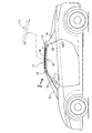
図1および図2に示すように、二人乗りの四輪2ドア車両は、左右のフロントピラー11,11と、その上端間を車幅方向に連結するフロントルーフアーチ12とによりフロントウインドウガラス13の左右両側縁および上縁が支持され、左右のリヤピラー14,14と、その上端間を車幅方向に連結するリヤルーフアーチ15とによりリヤウインドウガラス16の左右両側縁および上縁が支持される。フロントルーフアーチ12およびリヤルーフアーチ15に、着脱自在なルーフユニット17の前縁および後縁が固定される。ルーフユニット17は、中央に開口部18aが形成された矩形枠状の枠状ルーフ18を備えており、枠状ルーフ18の開口部18aがキャンバス19で開閉される。
As shown in FIGS. 1 and 2, a two-seater four-wheel two-door vehicle includes a
図2、図5および図6に示すように、枠状ルーフ18の前縁部18bの車幅方向両端部には左右一対の前部固定ピン20,20が設けられる。前部固定ピン20は、一端側に形成された係合部20aと、他端側に形成されたガイド部20bと、ガイド部20bの途中から直角方向に突出する操作部20cとを備え、枠状ルーフ18の前縁部18bは、前部固定ピン20の係合部20aが摺動自在に貫通するガイド孔18eと、前部固定ピン20のガイド部20bが摺動自在に嵌合するガイド筒18fと、前部固定ピン20の操作部20cを摺動自在に案内するL字状のガイド溝18gとが形成される。ガイド筒18fの内部にはスプリング21が圧縮状態で収納され、このスプリング21の弾発力で枠状ルーフ18の前縁部18bから前方に突出する方向に付勢された前部固定ピン20の係合部20aは、フロントルーフアーチ12の後面に形成したピン孔12aに係合可能である。
As shown in FIGS. 2, 5, and 6, a pair of left and right
同様に、枠状ルーフ18の後縁部18cの車幅方向両端部には前部固定ピン20,20と同一構造を有する左右一対の後部固定ピン22,22が設けられており、この後部固定ピン22,22はリヤルーフアーチ15の前面に形成したピン孔15a,15aに係合可能である。
Similarly, a pair of left and right
図2〜図4に示すように、枠状ルーフ18の左右の側縁部18d,18dに沿って前後方向に形成されたガイドレール23,23に、左右のスライダ24,24に設けたローラ25,25が転動可能に支持されており、左右のスライダ24,24を車幅方向に連結するロッド26に、後端が枠状ルーフ18の後縁部18cに固定されたキャンバス19の前端が固定される。左右の側縁部18d,18dの前部に設けた従動プーリ27,27と、左右の側縁部18d,18dの後部に設けた駆動プーリ28,28とに左右の無端ベルト29,29が巻き掛けられており、左右の無端ベルト29,29に左右のスライダ24,24がそれぞれ連結される。そして枠状ルーフ18の後部における車幅方向中央部に下向きに突設した凸部18hの内部に配置された電動モータおよび減速機よりなる駆動機構30(図4参照)が、フレキシブルシャフト31,31を介して駆動プーリ28,28に接続される。
As shown in FIGS. 2 to 4,
次に、上記構成を備える本発明の実施の形態の作用を説明する。 Next, the operation of the embodiment of the present invention having the above configuration will be described.
図5および図6に鎖線で示すように、不使用時のルーフユニット17の前部固定ピン20,20は、ガイド部20b,20bがスプリング21,21を圧縮する状態で操作部20c,20cがガイド溝18g,18gに係止されることで、ルーフユニット17の前縁部18b内に収納されており、同様に後部固定ピン22,22もルーフユニット17の後縁部18c内に収納されている、このルーフユニット17をフロントルーフアーチ12およびリヤルーフアーチ15に対して位置決めした状態で、前部固定ピン20,20および後部固定ピン22,22の操作部20c…を90°回転させると、図5および図6に実線で示すように、圧縮されたスプリング21…の弾発力で前部固定ピン20,20および後部固定ピン22,22が突出し、フロントルーフアーチ12のピン孔12a,12aおよびリヤルーフアーチ15のピン孔15a,15aにそれぞれ係合することで、ルーフユニット17がフロントルーフアーチ12およびリヤルーフアーチ15に装着される。
5 and 6, the
またルーフユニット17は、上記手順と逆の手順を行うことで、フロントルーフアーチ12およびリヤルーフアーチ15から取り外すことができる。
Further, the
図2〜図4において、駆動機構30を駆動すると、その駆動力がフレキシブルシャフト31,31を介して駆動プーリ28,28に伝達され、駆動プーリ28,28から従動プーリ27,27に巻き掛けられた左右の無端ベルト29,29が回転することで、スライダ24,24をガイドレール23,23に案内されたロッド26が前後方向に移動する。その結果、キャンバス19の前端が前後方向に移動し、前方に移動したときに開口部18aが閉じられ、後方に移動したときに開口部18aが開かれる。
2 to 4, when the
以上のように、タルガトップ車両は、フロントルーフアーチ12とリヤルーフアーチ15との間に着脱自在なルーフユニット17を支持するので、ルーフユニット17を取り外した状態で乗員の頭上にルーフサイドレールが存在せず、よって車室の開放感が高められる。しかもサーキット走行時のような車両運動性能を最大限に発揮させたい場合に、ルーフユニット17全体を取り外すことで車体重量を軽減することができる。
As described above, since the Targa top vehicle supports the
ルーフユニット17は、前部固定ピン20,20および後部固定ピン22,22をピン孔12a,12a;15a,15aに係合することでフロントルーフアーチ12およびリヤルーフアーチ15に固定されるので、ルーフユニット17の着脱作業が容易である。またルーフユニット17の枠状ルーフ18の開口部18aは展開および折り畳みが可能なキャンバス19により開閉可能であるので、取り外したルーフユニット17を保管する場所がない場合でも、ルーフユニット17を装着したままキャンバス19を折り畳んで開口部18aを開放することで開放感を得ることができる。しかも突然に雨が降り出したような場合に、ルーフユニット17を取り付ける場合に比べて、遥かに短時間でキャンバス19を展開して雨を避けることができる。
The
またキャンバス19を展開および折り畳みする駆動機構30を、ルーフユニット17の後部の車幅方向中央部の下面に設けた凸部18h内に配置したので、左右の座席に着座した乗員の頭部と凸部18hとの間にクリアランスを確保することができる。
Further, since the
以上、本発明の実施の形態を説明したが、本発明はその要旨を逸脱しない範囲で種々の設計変更を行うことが可能である。 The embodiments of the present invention have been described above, but various design changes can be made without departing from the scope of the present invention.
例えば、実施の形態ではキャンバス19を駆動機構30で展開および折り畳みするようになっているが、それを手動で行うようにしても良い。
For example, in the embodiment, the
12 フロントルーフアーチ
12a ピン孔
13 フロントウインドウガラス
15 リヤルーフアーチ
15a ピン孔
16 リヤウインドウガラス
17 ルーフユニット
18a 開口部
18h 凸部
19 キャンバス
20 前部固定ピン
22 後部固定ピン
30 駆動機構
12 Front roof arch
Claims (2)
前記ルーフユニット(17)は、進退可能な前部固定ピン(20)を前記フロントルーフアーチ(12)のピン孔(12a)に係合し、進退可能な後部固定ピン(22)を前記リヤルーフアーチ(15)のピン孔(15a)に係合することで前記フロントルーフアーチ(12)および前記リヤルーフアーチ(15)に固定され、前記ルーフユニット(17)の中央部に形成した開口部(18a)は展開および折り畳みが可能なキャンバス(19)により開閉可能であることを特徴とするタルガトップ車両のルーフ構造。 A detachable roof unit (17) is supported between the front roof arch (12) along the upper edge of the front window glass (13) and the rear roof arch (15) along the upper edge of the rear window glass (16). The roof structure of the Targa top vehicle that
The roof unit (17) engages a front fixing pin (20) that can be advanced and retracted with a pin hole (12a) of the front roof arch (12), and a rear fixing pin (22) that can be advanced and retracted. By engaging with the pin hole (15a) of the arch (15), it is fixed to the front roof arch (12) and the rear roof arch (15), and an opening formed in the center of the roof unit (17) ( 18a) is a roof structure of a Targa top vehicle, which can be opened and closed by a canvas (19) that can be expanded and folded.
The drive mechanism (30) for unfolding and folding the canvas (19) is disposed in a convex portion (18h) provided on the lower surface of the rear central portion of the roof unit (17) in the vehicle width direction. The roof structure of the Targa top vehicle according to claim 1.
Priority Applications (4)
| Application Number | Priority Date | Filing Date | Title |
|---|---|---|---|
| JP2016029785A JP2017144948A (en) | 2016-02-19 | 2016-02-19 | Roof structure of Targa top vehicle |
| GB1701453.1A GB2548001A (en) | 2016-02-19 | 2017-01-30 | Roof structure for targa top vehicle |
| DE102017202387.2A DE102017202387A1 (en) | 2016-02-19 | 2017-02-15 | Roof structure for Targa top vehicle |
| US15/434,566 US10005346B2 (en) | 2016-02-19 | 2017-02-16 | Roof structure for Targa top vehicle |
Applications Claiming Priority (1)
| Application Number | Priority Date | Filing Date | Title |
|---|---|---|---|
| JP2016029785A JP2017144948A (en) | 2016-02-19 | 2016-02-19 | Roof structure of Targa top vehicle |
Publications (1)
| Publication Number | Publication Date |
|---|---|
| JP2017144948A true JP2017144948A (en) | 2017-08-24 |
Family
ID=58462893
Family Applications (1)
| Application Number | Title | Priority Date | Filing Date |
|---|---|---|---|
| JP2016029785A Pending JP2017144948A (en) | 2016-02-19 | 2016-02-19 | Roof structure of Targa top vehicle |
Country Status (4)
| Country | Link |
|---|---|
| US (1) | US10005346B2 (en) |
| JP (1) | JP2017144948A (en) |
| DE (1) | DE102017202387A1 (en) |
| GB (1) | GB2548001A (en) |
Families Citing this family (2)
| Publication number | Priority date | Publication date | Assignee | Title |
|---|---|---|---|---|
| US10518617B2 (en) * | 2018-02-28 | 2019-12-31 | Honda Motor Co., Ltd. | Retractable headliner for vehicle convertible system |
| CN113561744B (en) * | 2021-07-23 | 2023-05-05 | 长春恒拓模具有限公司 | Sunroof structure of car |
Citations (2)
| Publication number | Priority date | Publication date | Assignee | Title |
|---|---|---|---|---|
| JPH06171371A (en) * | 1992-12-10 | 1994-06-21 | Daikyo Webasto Co Ltd | Sun roof opening/closing driving method |
| JP2014124970A (en) * | 2012-12-25 | 2014-07-07 | Toyo Seat Co Ltd | Vehicle roof structure and detachable roof |
Family Cites Families (15)
| Publication number | Priority date | Publication date | Assignee | Title |
|---|---|---|---|---|
| JPS55148658A (en) * | 1979-04-05 | 1980-11-19 | Nissan Shatai Co Ltd | Car body with air-flap effect |
| JPH0777849B2 (en) | 1986-08-29 | 1995-08-23 | マツダ株式会社 | Vehicle bus stop |
| US5018783A (en) * | 1989-09-19 | 1991-05-28 | Asc Incorporated | Slidable, foldable, and removable vehicle sunroof |
| JP2528249Y2 (en) | 1989-12-26 | 1997-03-05 | マツダ株式会社 | Car canvas top |
| JPH03279016A (en) * | 1990-03-29 | 1991-12-10 | Mazda Motor Corp | Canvas top construction for vehicle |
| DE4204827A1 (en) | 1992-02-18 | 1993-08-19 | Focke & Co | PACKING, IN PARTICULAR SOFT CUP PACK FOR CIGARETTES |
| US5360254A (en) * | 1992-02-26 | 1994-11-01 | Honda Giken Kogyo Kabushiki Kaisha | Automobile with movable roof storable in trunk lid |
| JP3347438B2 (en) | 1992-12-24 | 2002-11-20 | キヤノン株式会社 | Process unit and image forming apparatus |
| DE19927234C1 (en) * | 1999-06-15 | 2000-07-27 | Webasto Vehicle Sys Int Gmbh | Guide rail for accommodating displaceable vehicle roof part(s) has first section with centring element that interacts with complementary counter element on second section |
| DE19927237C1 (en) * | 1999-06-15 | 2000-09-28 | Webasto Vehicle Sys Int Gmbh | Vehicle roof has drive motor that actuates locking and/or unlocking of temporarily fixed roof part wrt. another at least temporarily fixed roof part |
| WO2005061253A1 (en) * | 2003-12-19 | 2005-07-07 | Ferrari S.P.A. | A motor vehicle provided with a folding top |
| US8857886B2 (en) * | 2004-03-02 | 2014-10-14 | Stephen G. Kimmet | Vehicle openings |
| US7909394B2 (en) * | 2007-12-06 | 2011-03-22 | Magna International Inc. | Foldable/stowable roof system |
| US9090149B1 (en) * | 2014-03-13 | 2015-07-28 | Honda Motor Co., Ltd. | Convertible system for a vehicle |
| US9776488B2 (en) * | 2015-03-10 | 2017-10-03 | Webasto-Edscha Cabrio GmbH | Vehicle roof and roof opening mechanism |
-
2016
- 2016-02-19 JP JP2016029785A patent/JP2017144948A/en active Pending
-
2017
- 2017-01-30 GB GB1701453.1A patent/GB2548001A/en not_active Withdrawn
- 2017-02-15 DE DE102017202387.2A patent/DE102017202387A1/en not_active Ceased
- 2017-02-16 US US15/434,566 patent/US10005346B2/en active Active
Patent Citations (2)
| Publication number | Priority date | Publication date | Assignee | Title |
|---|---|---|---|---|
| JPH06171371A (en) * | 1992-12-10 | 1994-06-21 | Daikyo Webasto Co Ltd | Sun roof opening/closing driving method |
| JP2014124970A (en) * | 2012-12-25 | 2014-07-07 | Toyo Seat Co Ltd | Vehicle roof structure and detachable roof |
Also Published As
| Publication number | Publication date |
|---|---|
| US20170240032A1 (en) | 2017-08-24 |
| DE102017202387A1 (en) | 2017-08-24 |
| US10005346B2 (en) | 2018-06-26 |
| GB201701453D0 (en) | 2017-03-15 |
| GB2548001A (en) | 2017-09-06 |
Similar Documents
| Publication | Publication Date | Title |
|---|---|---|
| US9340095B2 (en) | Sun shield device for windshield | |
| US7240960B2 (en) | Modular convertible top | |
| US6322130B1 (en) | Folding top mechanism for a convertible, rollover protection system, and a convertible | |
| US6857693B2 (en) | Sun screen for a motor vehicle | |
| EP1419057B1 (en) | Sliding sun visor | |
| JP2001354037A (en) | Vehicle provided with openable vehicular roof | |
| JP5050690B2 (en) | Sunshade equipment | |
| JP2017144948A (en) | Roof structure of Targa top vehicle | |
| US9090149B1 (en) | Convertible system for a vehicle | |
| JP5311902B2 (en) | Movable roof for passenger cars | |
| US20070152467A1 (en) | Motor vehicle with movable roof part | |
| JP4016314B2 (en) | Automotive seat | |
| US10518617B2 (en) | Retractable headliner for vehicle convertible system | |
| US7320499B2 (en) | Movable roof drive system | |
| US9963026B2 (en) | Convertible vehicle having a backbench and a wind deflector arrangement | |
| EP3106330B1 (en) | Vehicle roof having a movable roof device | |
| JP5948911B2 (en) | Opening and closing device for vehicle roof | |
| JP4207594B2 (en) | Vehicle roof trim | |
| US10875389B2 (en) | Top arrangement having a top cover | |
| JP6762815B2 (en) | Sunshade device | |
| JP2006335078A (en) | Sunshade device for vehicle | |
| JP4352431B2 (en) | Canvas storage structure | |
| JP6593650B2 (en) | Sunshade equipment | |
| JP2016084069A (en) | Sunshade device, sliding member of the same and vehicle provided with the sunshade device | |
| JPH07125541A (en) | Open car body structure |
Legal Events
| Date | Code | Title | Description |
|---|---|---|---|
| A131 | Notification of reasons for refusal |
Free format text: JAPANESE INTERMEDIATE CODE: A131 Effective date: 20170809 |
|
| A521 | Request for written amendment filed |
Free format text: JAPANESE INTERMEDIATE CODE: A523 Effective date: 20171010 |
|
| A02 | Decision of refusal |
Free format text: JAPANESE INTERMEDIATE CODE: A02 Effective date: 20180221 |