EP1059645A2 - Dünnes Seltenerd-Legierungsband für Dauermagnet - Google Patents
Dünnes Seltenerd-Legierungsband für Dauermagnet Download PDFInfo
- Publication number
- EP1059645A2 EP1059645A2 EP00401552A EP00401552A EP1059645A2 EP 1059645 A2 EP1059645 A2 EP 1059645A2 EP 00401552 A EP00401552 A EP 00401552A EP 00401552 A EP00401552 A EP 00401552A EP 1059645 A2 EP1059645 A2 EP 1059645A2
- Authority
- EP
- European Patent Office
- Prior art keywords
- phase
- iron
- volume fraction
- rare earth
- average grain
- Prior art date
- Legal status (The legal status is an assumption and is not a legal conclusion. Google has not performed a legal analysis and makes no representation as to the accuracy of the status listed.)
- Granted
Links
Images


Classifications
-
- H—ELECTRICITY
- H01—ELECTRIC ELEMENTS
- H01F—MAGNETS; INDUCTANCES; TRANSFORMERS; SELECTION OF MATERIALS FOR THEIR MAGNETIC PROPERTIES
- H01F1/00—Magnets or magnetic bodies characterised by the magnetic materials therefor; Selection of materials for their magnetic properties
- H01F1/01—Magnets or magnetic bodies characterised by the magnetic materials therefor; Selection of materials for their magnetic properties of inorganic materials
- H01F1/03—Magnets or magnetic bodies characterised by the magnetic materials therefor; Selection of materials for their magnetic properties of inorganic materials characterised by their coercivity
- H01F1/032—Magnets or magnetic bodies characterised by the magnetic materials therefor; Selection of materials for their magnetic properties of inorganic materials characterised by their coercivity of hard-magnetic materials
- H01F1/04—Magnets or magnetic bodies characterised by the magnetic materials therefor; Selection of materials for their magnetic properties of inorganic materials characterised by their coercivity of hard-magnetic materials metals or alloys
- H01F1/047—Alloys characterised by their composition
- H01F1/053—Alloys characterised by their composition containing rare earth metals
- H01F1/055—Alloys characterised by their composition containing rare earth metals and magnetic transition metals, e.g. SmCo5
- H01F1/057—Alloys characterised by their composition containing rare earth metals and magnetic transition metals, e.g. SmCo5 and IIIa elements, e.g. Nd2Fe14B
- H01F1/0571—Alloys characterised by their composition containing rare earth metals and magnetic transition metals, e.g. SmCo5 and IIIa elements, e.g. Nd2Fe14B in the form of particles, e.g. rapid quenched powders or ribbon flakes
- H01F1/0575—Alloys characterised by their composition containing rare earth metals and magnetic transition metals, e.g. SmCo5 and IIIa elements, e.g. Nd2Fe14B in the form of particles, e.g. rapid quenched powders or ribbon flakes pressed, sintered or bonded together
- H01F1/0577—Alloys characterised by their composition containing rare earth metals and magnetic transition metals, e.g. SmCo5 and IIIa elements, e.g. Nd2Fe14B in the form of particles, e.g. rapid quenched powders or ribbon flakes pressed, sintered or bonded together sintered
-
- H—ELECTRICITY
- H01—ELECTRIC ELEMENTS
- H01F—MAGNETS; INDUCTANCES; TRANSFORMERS; SELECTION OF MATERIALS FOR THEIR MAGNETIC PROPERTIES
- H01F1/00—Magnets or magnetic bodies characterised by the magnetic materials therefor; Selection of materials for their magnetic properties
- H01F1/01—Magnets or magnetic bodies characterised by the magnetic materials therefor; Selection of materials for their magnetic properties of inorganic materials
- H01F1/03—Magnets or magnetic bodies characterised by the magnetic materials therefor; Selection of materials for their magnetic properties of inorganic materials characterised by their coercivity
- H01F1/032—Magnets or magnetic bodies characterised by the magnetic materials therefor; Selection of materials for their magnetic properties of inorganic materials characterised by their coercivity of hard-magnetic materials
- H01F1/04—Magnets or magnetic bodies characterised by the magnetic materials therefor; Selection of materials for their magnetic properties of inorganic materials characterised by their coercivity of hard-magnetic materials metals or alloys
- H01F1/047—Alloys characterised by their composition
- H01F1/053—Alloys characterised by their composition containing rare earth metals
- H01F1/055—Alloys characterised by their composition containing rare earth metals and magnetic transition metals, e.g. SmCo5
- H01F1/057—Alloys characterised by their composition containing rare earth metals and magnetic transition metals, e.g. SmCo5 and IIIa elements, e.g. Nd2Fe14B
- H01F1/0571—Alloys characterised by their composition containing rare earth metals and magnetic transition metals, e.g. SmCo5 and IIIa elements, e.g. Nd2Fe14B in the form of particles, e.g. rapid quenched powders or ribbon flakes
Definitions
- the present invention relates to a thin ribbon of a rare earth-based permanent magnet alloy, referred to simply as a thin alloy ribbon hereinafter, or more particularly, to a thin alloy ribbon which can be an intermediate material for the preparation of a sintered permanent magnet of the R/T/B-type or, in particular, neodymium/iron/boron-type having excellent magnetic properties.
- the so-called R/T/B-type magnet alloys or, typically, the neodymium/iron/boron-type magnet alloys are highlighted in respects of their high magnetic properties and relatively low material costs among the rare earth-based permanent magnet alloys.
- the magnet alloys of this type are prepared usually by the metal-mold casting method or by the strip casting method.
- the magnet alloy is obtained in the form of an ingot by casting a melt of the alloy into a metal-made casting mold.
- This method is advantageous because a magnet alloy of an exactly controlled chemical composition can readily be obtained so that this method is widely employed.
- the metal-mold casting method has a serious problem due to the relatively low rate of heat transfer between the casting mold and the alloy melt cast therein and within the magnet alloy per se necessitating a relatively long time for solidification of the molten alloy resulting in precipitation of the ⁇ -iron phase as the primary crystals in the course of solidification of the molten alloy with remaining ⁇ -iron phase of a coarse grain size of 10 ⁇ m or larger in the core portion of the ingot after solidification by cooling.
- the grain size of the R-rich phase and R X T 4 B 4 phase surrounding the R 2 T 14 B phase also cannot be fine enough.
- the ⁇ -iron phase and R-rich phase as precipitated may have a wide variation in the grain diameters so that the particle size distribution of the alloy particles prepared by pulverization of the alloy ingot is broad due to the difficulties encountered in the pulverization of the ingot into fine particles of a particle diameter of a few micrometers. Accordingly, the magnet alloy particles are inferior in the behavior for magnetic orientation and sintering resulting in a decrease in the magnetic properties of the sintered permanent magnets as the final products.
- a melt of the magnet alloy is continuously ejected at the surface of a rotating quenching roller of the single-roller type or twin-roller type so that the alloy melt is rapidly solidified on the roller surface in the form of a thin ribbon of the alloy having a thickness of 0.01 to 5 mm.
- This method is advantageous because of the possibility of controlling precipitation of the ⁇ -iron phase and accomplishing fine and uniform dispersion of the R X T 4 B 4 phase by adequately selecting the quenching conditions of the alloy melt consequently leading to a uniform structure of the magnet to obtain high performance R/T/B-type permanent magnets.
- Japanese Patent No. 2639609 directing attention to the precipitation type of the ⁇ -iron phase in and the metallographic structure of the strip casts, discloses a thin alloy ribbon having a structure in which ⁇ -iron grains having a grain diameter smaller than 10 ⁇ m are dispersed as the peritectic nuclei in the crystalline grains of the principal phase.
- Japanese Patent Kokai 7-176414 proposes a thin alloy ribbon having a structure substantially free from segregation of the ⁇ -iron phase.
- Japanese Patent Kokai 10-317110 proposes, directing attention to the fine chill crystalline structure as formed in the vicinity of the solidification front, a rare earth-based magnet alloy for a base material of sintered permanent magnets.
- the object of the present invention is therefore to provide a thin alloy ribbon capable of giving a high performance rare earth-based sintered permanent magnets of improved magnetic properties by positively utilizing the four-phase coexisting region and the chill crystalline phase.
- the present invention provides a thin alloy ribbon as a base material of a sintered rare earth-based permanent magnet as prepared by the strip casting method from a melt of an alloy comprising a rare earth element R selected from the group consisting of praseodymium, neodymium, terbium and dysprosium, iron, optionally, in combination with a transition metal element other than iron and rare earth elements T and boron B, which comprises from 1 to 10% or, preferably, from 2 to 5% by volume fraction of the four-phase coexisting region consisting of the ⁇ -iron phase having an average grain diameter of 0.1 to 20 ⁇ m, R-rich phase having an average grain diameter of 0.1 to 20 ⁇ m, R X T 4 B 4 phase, the subscript x being 1 + ⁇ , having an average grain diameter of 0.1 to 10 ⁇ m and R 2 T 14 B phase having an average grain diameter of 0.1 to 20 ⁇ m and from 1 to 30% by volume fraction of a chill crystalline phase having an average grain diameter not exceeding 3 ⁇
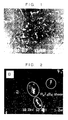
- Figure 1 is a reflection electron pattern of the four-phase coexisting region of the thin alloy ribbon for permanent magnets.
- Figure 2 is an Auger electron microscopic photograph of boron in the thin alloy ribbon for permanent magnets.
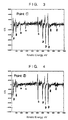
- Figure 3 is an Auger electron spectrum of the thin alloy ribbon for permanent magnets in the region indicated by 1 ⁇ in Figure 2.
- Figure 4 is an Auger electron spectrum of the thin alloy ribbon for permanent magnets in the region indicated by 2 ⁇ in Figure 2.
- Figure 5 is a graph showing the residual magnetic flux density Br of permanent magnets as a function of the volume fraction of the four-phase coexisting region (Example 1).
- Figure 6 is a graph showing the residual magnetic flux density Br of permanent magnets as a function of the volume fraction of the four-phase coexisting region (Example 2).
- Figure 7 is a (006) polar diagram when the volume fraction of the four-phase coexisting region is 0.5%.
- Figure 8 is a (006) polar diagram when the volume fraction of the four-phase coexisting region is 3%.
- the above described thin alloy ribbon of the present invention has been established on the base of the inventors' discovery that the magnetic properties of the sintered permanent magnets are greatly influenced by the volume fraction of the four-phase coexisting region in the thin alloy ribbon precipitated when an alloy melt is quenched by the strip casting method and the average grain diameters of the four phases constituting the four-phase coexisting region and that improved magnetic properties can be accomplished by sintering of the magnet at a temperature lower than conventional when the chill crystalline phase having an average grain diameter not exceeding 3 ⁇ m are contained in a specific volume fraction as formed in the vicinity of the solidification front.
- inventive thin alloy ribbon include a first constituent denoted by R which is a specific rare earth element, a second constituent denoted by T which is iron optionally in combination with another transition element and a third constituent denoted by B which is boron.
- the thin alloy ribbon of the invention is prepared by the strip casting method in which a melt of an alloy consisting of these essential and optional elements is continuously ejected at the surface of a rotating quenching roller of the single-roller type or twin-roller type so as to be solidified in the form of a ribbon having a thickness of 10 to 500 ⁇ m and a width of 5 to 500 mm.
- the conditions of quenching should be controlled in such a way that the requirements for the volume fractions of the four-phase coexisting region and the chill crystalline phase as well as the average diameters of the four phases constituting the four-phase coexisting region are satisfied.
- Precipitation of the four-phase coexisting regions and chilled crystals can be controlled by means of the material, thickness and diameter of the quenching roller, peripheral velocity of the quenching roller, rate of melt discharge out of the tundish and others.
- the thin alloy ribbons obtained have a thickness of 100 to 500 ⁇ m, in which the volume fractions of the four-phase coexisting regions and the chill crystals can well be controlled within the above mentioned ranges.
- the average grain diameters of the four phases constituting the four-phase coexisting region including the ⁇ -iron phase, R-rich phase, R X T 4 B 4 phase and R 2 T 14 B phase should be in the ranges of from 0.1 to 20 ⁇ m, from 0.1 to 20 ⁇ m, from 0.1 to 10 ⁇ m and from 0.1 to 20 ⁇ m, respectively.
- the reaction of these fine grains proceeds so actively that the R 2 T 14 B phase newly formed by the reaction is bonded to the magnetically oriented existing R 2 T 14 B phase without disturbing the magnetic orientation. Since the reaction proceeds among fine grains of the respective phases, furthermore, an improvement can be obtained in the sintering behavior of the alloy powder to give a sintered permanent magnet having an increased density of the sintered body and increased residual magnetic flux density. This advantageous effect can hardly be obtained when the average grain diameters of the respective phases do not satisfy the requirements.
- the value of ⁇ which is 0.1 or a number somewhat larger than 0.1 depending on the rare earth elements, as reported includes the values of 0.10-0.11 for praseodymium, 0.10-0.11 for neodymium, 0.14-0.16 for terbium and 0.15-0.16 for dysprosium.
- the crystalline grains essentially have a grain diameter in the range from 0.1 to 20 ⁇ m or, preferably, from 0.1 to 10 ⁇ m, from 0.1 to 20 ⁇ m or, preferably, from 0.1 to 10 ⁇ m, from 0.1 to 10 ⁇ m or, preferably, from 0.1 to 5 ⁇ m and from 0.1 to 20 ⁇ m or, preferably, from 0.1 to 10 ⁇ m, respectively.
- the volume fraction of the four-phase coexisting region in the inventive thin alloy ribbon should be in the range from 1 to 10% or, preferably, from 2 to 5%. When the volume fraction thereof is too large, a great decrease is caused in the coercive force and residual magnetic flux density of the permanent magnets prepared from the thin alloy ribbon. When the volume fraction of the region is too small, no substantial improvement can be obtained in the residual magnetic flux density of the permanent magnet.
- the volume fraction of the four-phase coexisting region can be determined from the secondary electron pattern or reflection electronic composition pattern of a cross section of the thin alloy ribbon.
- the thin alloy ribbon of the present invention comprises the chill crystalline phase having an average grain diameter not exceeding 3 ⁇ m in the range from 1 to 30% volume fraction as formed in the vicinity of the solidification front when the alloy melt is quenched by contacting with the surface of the rotating quenching roller.
- the volume fraction of the chill crystalline phase having an average grain diameter not exceeding 3 ⁇ m is within the above mentioned range, the reaction taking place among the phases constituting the four-phase coexisting region is promoted so that the reaction can proceed at a temperature lower by 10 to 50 °C than in the absence of the chill crystalline phase.
- the volume fraction of the chill crystalline phase having an average grain diameter not exceeding 3 ⁇ m is too large, however, the coercive force of the permanent magnet is decreased because the fine particles are highly active and readily oxidized.
- the volume fraction of the chill crystalline phase having an average grain diameter not exceeding 3 ⁇ m in the inventive thin alloy ribbon can be determined from a reflection electronic composition pattern or from a polarizing microscopic photograph.
- the present invention is described in more detail by way of Examples, which, however, never limit the scope of the invention in any way.
- the thin magnet alloy ribbons obtained in the above described manner were subjected to hydrogen decrepitation or mechanical pulverization by using a grinding machine such as a jet mill and Brown mill into fine particles, which were compression-molded in a magnetic field into a powder compact.
- the powder compact was subjected to a sintering heat treatment at a temperature of 900 to 1150°C in an inert atmosphere of argon followed by an aging heat treatment at a temperature of 400 to 600°C to give a rare earth-based sintered permanent magnet.
- Neodymium, dysprosium, electrolytic iron, ferroboron, cobalt, aluminum and copper each in the elementary or metallic form were taken as the starting materials in a weight proportion of 30% Nd, 1% Dy, 4% Co, 1% B, 0.3% Al and 0.2% Cu, the balance being iron, and thin alloy ribbons having a thickness of from 50 to 1000 ⁇ m were prepared from an alloy melt of this composition by the strip casting method under varied quenching conditions including the peripheral velocity of the quenching roller of from 2.0 to 10.0 meters/second and melt discharge rate of from 3.0 to 15.0 g/second.
- the conditions of quenching in this strip casting process were controlled such that the volume fraction of the four-phase coexisting region fell within the range up to 13.7% and the volume fraction of the chill crystalline phase fell within the range from 10 to 15%.
- the average grain diameters of the ⁇ -iron phase, R-rich phase, R X T 4 B 4 phase and R 2 T 14 B phase constituting the four-phase coexisting region were 3 ⁇ m, 7 ⁇ m, 1 ⁇ m and 10 ⁇ m, respectively.
- Figure 1 is a reflection electron pattern of a cross section of one of the above prepared thin alloy ribbons, of which the volume fraction of the four-phase coexisting region was 5%.
- the black areas, gray areas and white areas correspond to the ⁇ -iron phase, R 2 T 14 B phase and R-rich phase, respectively, each dispersed finely in the others within the four-phase coexisting region.
- the R X T 4 B 4 phase could not be exhibited on the pattern with such definiteness as to enable determination of the average grain diameter due to fineness of the grains and the high content of boron which was hardly detectable by the reflection electrons.
- Figure 2 is an Auger electron pattern of boron in the four-phase coexisting region of the same thin alloy ribbon as above.
- Figures 3 and 4 are each an Auger electron spectrum of the spots indicated by the marks 1 ⁇ and 2 ⁇ , respectively, on Figure 2.
- the spot of 1 ⁇ found within the four-phase coexisting region is a phase of R X T 4 B 4 which is rich in the content of boron as compared with the spot 2 ⁇ of the marginal phase.
- the average grain diameter of the R X T 4 B 4 phase was about 1 to 3 ⁇ m as determined from this figure.
- the thus prepared thin alloy ribbons were subjected to a hydrogen decrepitation treatment and then finely pulverized in a jet mill with nitrogen as the jet gas into fine particles having an average particle diameter of about 3 ⁇ m.
- the thus prepared fine alloy powder was put into a metal mold and shaped by compression-molding in a magnetic field of 12 kOe under a compressive force of 1 ton/cm 2 in a direction perpendicular to the direction of the magnetic field.
- the thus obtained powder compacts were sintered in an atmosphere of argon at 1050 °C for 2 hours followed by cooling and then subjected to an aging treatment also in an atmosphere of argon at 500 °C for 1 hour to give permanent magnets of different alloy compositions.
- Thin alloy ribbons having a thickness of 50 to 1000 ⁇ m were prepared in about the same manner as in Example 1 from an alloy melt consisting of 28% by weight of neodymium, 0.3% by weight of dysprosium, 1% by weight of cobalt, 1.1% by weight of boron, 0.3% by weight of aluminum and 0.1% by weight of copper, the balance being iron.
- the quenching conditions in the strip casting process were controlled in such a way that the volume fraction of the four-phase coexisting region was in the range up to 13.5% and the volume fraction of the chill crystalline phase was in the range up to about 14%.
- the average grain diameters of the ⁇ -iron phase, R-rich phase, R X T 4 B 4 phase and R 2 T 14 B phase in the four-phase coexisting region were 3 ⁇ m, 5 ⁇ m, 1 ⁇ m and 15 ⁇ m, respectively.
- These thin alloy ribbons were processed into permanent magnets in the same manner as in Example 1 except that each of the fine powders of the thin alloy ribbons was admixed with 10% by weight of a sintering aid and the sintering temperature was 1070 °C.
- the sintering aid was an alloy composition consisting of 45% of neodymium, 15% of dysprosium, 20% of cobalt, 0.5% of boron, 1.0% of calcium and 0.5% of aluminum in atomic proportions, the balance being iron.
- the sintered bodies prepared from powders of the thin alloy ribbons in which the volume fraction of the four-phase coexisting region was 0.5% and 3% were subjected to the measurement of the (006) X-ray polar diagrams to estimate the influence of the volume fraction on the degree of crystalline orientation in the sintered bodies to give the results shown in Figure 7 and Figure 8, respectively.
- the distribution density of the contour lines in Figure 8 is much larger than in Figure 7 indicating a great influence of the volume fraction of the four-phase coexisting region on the degree of orientation.
- the magnetic properties including residual magnetic flux density Br, coercive force iHc and maximum energy product (BH) max and the sintering density d are shown in Table 1 for the permanent magnet prepared from the thin alloy ribbon in which the volume fractions of the four-phase coexisting region and the chill crystalline phase were 10.0% and 3.1%, respectively.
- Thin alloy ribbons having a thickness of 800 ⁇ m were prepared in about the same manner as in Example 1 except that the peripheral velocity of the quenching roller was 7 meters/second and the melt discharge rate was 12 g/second from an alloy melt consisting of 28% by weight of neodymium, 0.3% by weight of dysprosium, 1% by weight of cobalt, 1.1% by weight of boron, 0.3% by weight of aluminum and 0.1% by weight of copper, the balance being iron.
- the quenching conditions in the strip casting process were controlled in such a way that the volume fraction of the four-phase coexisting region was 2.1% and the volume fraction of the chill crystalline phase was 10%.
- the average grain diameters of the ⁇ -iron phase, R-rich phase, R X T 4 B 4 phase and R 2 T 14 B phase in the four-phase coexisting region were 20 ⁇ m, 15 ⁇ m, 7 ⁇ m and 10 ⁇ m, respectively.
- the thin alloy ribbons were processed into permanent magnets in the same way as in Example 1 except that the fine powder of the thin alloy ribbons was admixed with 10% by weight of the sintering aid and the sintering temperature was 1090 °C.
- Thin alloy ribbons having a thickness of 700 ⁇ m were prepared in about the same manner and from an alloy melt of the same alloy composition as in Comparative Example 3 except that the quenching conditions were controlled in such a way that the volume fraction of the four-phase coexisting region was 1.9% and the volume fraction of the chill crystalline phase was 0.2%.
- the peripheral velocity of the quenching roller was 5 meters/second and the melt discharge rate was 10 g/second.
- the average grain diameters of the ⁇ -iron phase, R-rich phase, R X T 4 B 4 phase and R 2 T 14 B phase in the four-phase coexisting region were 3 ⁇ m, 5 ⁇ m, 1 ⁇ m and 13 ⁇ m, respectively.
- the thin alloy ribbons were processed into permanent magnets in the same way as in Comparative Example 3 except that the sintering temperature was 1100 °C.
- Thin alloy ribbons having a thickness of 500 ⁇ m were prepared in about the same manner and from an alloy melt of the same alloy composition as in Comparative Example 3 except that the quenching conditions were controlled in such a way that the four-phase coexisting region was not formed and the volume fraction of the chill crystalline phase was 0.5%.
- the peripheral velocity of the quenching roller was 5 meters/second and the melt discharge rate was 7 g/second.
- the thin alloy ribbons were processed into permanent magnets in the same manner as in Comparative Example 3 except that the sintering temperature was 1100 °C.
- the sintered permanent magnet suffer, as a trend, a decrease in the squareness ratio and, further, a decrease in the residual magnetic flux density when the ⁇ -iron phase, R-rich phase, R X T 4 B 4 phase and R 2 T 14 B phase has a large average grain diameter.
Landscapes
- Chemical & Material Sciences (AREA)
- Crystallography & Structural Chemistry (AREA)
- Inorganic Chemistry (AREA)
- Engineering & Computer Science (AREA)
- Power Engineering (AREA)
- Hard Magnetic Materials (AREA)
- Manufacturing Cores, Coils, And Magnets (AREA)
Applications Claiming Priority (2)
| Application Number | Priority Date | Filing Date | Title |
|---|---|---|---|
| JP16064899 | 1999-06-08 | ||
| JP16064899 | 1999-06-08 |
Publications (3)
| Publication Number | Publication Date |
|---|---|
| EP1059645A2 true EP1059645A2 (de) | 2000-12-13 |
| EP1059645A3 EP1059645A3 (de) | 2001-01-03 |
| EP1059645B1 EP1059645B1 (de) | 2006-06-14 |
Family
ID=15719487
Family Applications (1)
| Application Number | Title | Priority Date | Filing Date |
|---|---|---|---|
| EP00401552A Expired - Lifetime EP1059645B1 (de) | 1999-06-08 | 2000-05-31 | Dünnes Band einer dauermagnetischen Legierung auf Seltenerdbasis |
Country Status (3)
| Country | Link |
|---|---|
| US (2) | US6322637B1 (de) |
| EP (1) | EP1059645B1 (de) |
| DE (1) | DE60028659T2 (de) |
Cited By (2)
| Publication number | Priority date | Publication date | Assignee | Title |
|---|---|---|---|---|
| WO2013027109A1 (en) * | 2011-08-23 | 2013-02-28 | Toyota Jidosha Kabushiki Kaisha | Method for producing rare earth magnets, and rare earth magnets |
| CN104078176A (zh) * | 2013-03-28 | 2014-10-01 | Tdk株式会社 | 稀土类磁体 |
Families Citing this family (13)
| Publication number | Priority date | Publication date | Assignee | Title |
|---|---|---|---|---|
| US6319335B1 (en) * | 1999-02-15 | 2001-11-20 | Shin-Etsu Chemical Co., Ltd. | Quenched thin ribbon of rare earth/iron/boron-based magnet alloy |
| DE60028659T2 (de) * | 1999-06-08 | 2007-05-31 | Shin-Etsu Chemical Co., Ltd. | Dünnes Band einer dauermagnetischen Legierung auf Seltenerdbasis |
| US6676773B2 (en) * | 2000-11-08 | 2004-01-13 | Sumitomo Special Metals Co., Ltd. | Rare earth magnet and method for producing the magnet |
| WO2003001541A1 (fr) * | 2001-06-22 | 2003-01-03 | Sumitomo Special Metals Co., Ltd. | Aimant des terres rares et procede de production dudit aimant |
| US7014718B2 (en) * | 2001-09-03 | 2006-03-21 | Showa Denko K.K. | Rare earth magnet alloy ingot, manufacturing method for the same, R-T-B type magnet alloy ingot, R-T-B type magnet, R-T-B type bonded magnet, R-T-B type exchange spring magnet alloy ingot, R-T-B type exchange spring magnet, and R-T-B type exchange spring bonded magnet |
| CN1306527C (zh) * | 2001-12-18 | 2007-03-21 | 昭和电工株式会社 | 用于稀土磁体的合金薄片及其生产方法、用于稀土烧结磁体的合金粉末、稀土烧结磁体、用于结合磁体的合金粉末和结合磁体 |
| JP4389427B2 (ja) * | 2002-02-05 | 2009-12-24 | 日立金属株式会社 | 希土類−鉄−硼素系磁石用合金粉末を用いた焼結磁石 |
| US7705233B2 (en) * | 2002-08-13 | 2010-04-27 | Showa Denko K.K. | Filled skutterudite-based alloy, production method thereof and thermoelectric conversion device fabricated using the alloy |
| US7311788B2 (en) * | 2002-09-30 | 2007-12-25 | Tdk Corporation | R-T-B system rare earth permanent magnet |
| US7199690B2 (en) * | 2003-03-27 | 2007-04-03 | Tdk Corporation | R-T-B system rare earth permanent magnet |
| US7314531B2 (en) * | 2003-03-28 | 2008-01-01 | Tdk Corporation | R-T-B system rare earth permanent magnet |
| JP5949775B2 (ja) * | 2011-10-13 | 2016-07-13 | Tdk株式会社 | R−t−b系焼結磁石及びその製造方法、並びに回転機 |
| JP6142794B2 (ja) * | 2013-12-20 | 2017-06-07 | Tdk株式会社 | 希土類磁石 |
Family Cites Families (13)
| Publication number | Priority date | Publication date | Assignee | Title |
|---|---|---|---|---|
| DE3587977T2 (de) * | 1984-02-28 | 1995-05-18 | Sumitomo Spec Metals | Dauermagnete. |
| US4767450A (en) * | 1984-11-27 | 1988-08-30 | Sumitomo Special Metals Co., Ltd. | Process for producing the rare earth alloy powders |
| US4765848A (en) * | 1984-12-31 | 1988-08-23 | Kaneo Mohri | Permanent magnent and method for producing same |
| JPH0789521B2 (ja) * | 1985-03-28 | 1995-09-27 | 株式会社東芝 | 希土類鉄系永久磁石 |
| DE3676403D1 (de) * | 1985-09-10 | 1991-02-07 | Toshiba Kawasaki Kk | Dauermagnet. |
| JPS62165305A (ja) * | 1986-01-16 | 1987-07-21 | Hitachi Metals Ltd | 熱安定性良好な永久磁石およびその製造方法 |
| EP0261579B1 (de) * | 1986-09-16 | 1993-01-07 | Tokin Corporation | Verfahren zur Herstellung eines Seltenerd-Eisen-Bor-Dauermagneten mit Hilfe eines abgeschreckten Legierungspuders |
| KR880013194A (ko) * | 1987-04-06 | 1988-11-30 | 원본미기재 | 영구자석 및 그 제조방법 |
| US4919732A (en) * | 1988-07-25 | 1990-04-24 | Kubota Ltd. | Iron-neodymium-boron permanent magnet alloys which contain dispersed phases and have been prepared using a rapid solidification process |
| FR2655355B1 (fr) * | 1989-12-01 | 1993-06-18 | Aimants Ugimag Sa | Alliage pour aimant permanent type fe nd b, aimant permanent fritte et procede d'obtention. |
| DE69318147T2 (de) * | 1993-07-06 | 1998-11-12 | Sumitomo Spec Metals | R-Fe-B Dauermagnetmaterialien und ihre Herstellungsverfahren |
| US6319335B1 (en) * | 1999-02-15 | 2001-11-20 | Shin-Etsu Chemical Co., Ltd. | Quenched thin ribbon of rare earth/iron/boron-based magnet alloy |
| DE60028659T2 (de) * | 1999-06-08 | 2007-05-31 | Shin-Etsu Chemical Co., Ltd. | Dünnes Band einer dauermagnetischen Legierung auf Seltenerdbasis |
-
2000
- 2000-05-31 DE DE60028659T patent/DE60028659T2/de not_active Expired - Lifetime
- 2000-05-31 EP EP00401552A patent/EP1059645B1/de not_active Expired - Lifetime
- 2000-06-07 US US09/588,536 patent/US6322637B1/en not_active Expired - Lifetime
-
2001
- 2001-08-31 US US09/943,273 patent/US6419723B2/en not_active Expired - Lifetime
Cited By (3)
| Publication number | Priority date | Publication date | Assignee | Title |
|---|---|---|---|---|
| WO2013027109A1 (en) * | 2011-08-23 | 2013-02-28 | Toyota Jidosha Kabushiki Kaisha | Method for producing rare earth magnets, and rare earth magnets |
| CN104078176A (zh) * | 2013-03-28 | 2014-10-01 | Tdk株式会社 | 稀土类磁体 |
| CN104078176B (zh) * | 2013-03-28 | 2017-06-23 | Tdk株式会社 | 稀土类磁体 |
Also Published As
| Publication number | Publication date |
|---|---|
| US6322637B1 (en) | 2001-11-27 |
| DE60028659D1 (de) | 2006-07-27 |
| EP1059645B1 (de) | 2006-06-14 |
| EP1059645A3 (de) | 2001-01-03 |
| DE60028659T2 (de) | 2007-05-31 |
| US20020017340A1 (en) | 2002-02-14 |
| US6419723B2 (en) | 2002-07-16 |
Similar Documents
| Publication | Publication Date | Title |
|---|---|---|
| US5022939A (en) | Permanent magnets | |
| US5049208A (en) | Permanent magnets | |
| EP0251871B1 (de) | Dauermagnet auf der Basis der seltenen Erden | |
| Kim et al. | High performance NdFeB magnets | |
| EP1030317B1 (de) | Abgeschrecktes, dünnes Band aus einer Magnetlegierung auf Basis Seltene Erde/Eisen/Bor | |
| US6506265B2 (en) | R-Fe-B base permanent magnet materials | |
| US6322637B1 (en) | Thin ribbon of rare earth-based permanent magnet alloy | |
| Ormerod | The physical metallurgy and processing of sintered rare earth permanent magnets | |
| JP3267133B2 (ja) | 希土類磁石用合金及びその製造方法並びに永久磁石の製造方法 | |
| EP0557103A1 (de) | Vorlegierung zur Herstellung von Magneten und deren Produktion sowie Magnet-Herstellung | |
| US5200001A (en) | Permanent magnet | |
| JP4121039B2 (ja) | 微細結晶組織を有する薄板磁石 | |
| JP2000114017A (ja) | 永久磁石材料および永久磁石 | |
| JPH1036949A (ja) | 希土類磁石用合金及びその製造方法 | |
| EP1017065B1 (de) | Magnetfolie mit mikrokristallinen struktur, und herstellungsverfahren desselben, und herstellungsverfahren eines isotropen permanentmagnet-pulver | |
| JP3488358B2 (ja) | 微細結晶永久磁石合金及び永久磁石粉末の製造方法 | |
| WO2021193334A1 (ja) | 異方性希土類焼結磁石及びその製造方法 | |
| US8182618B2 (en) | Rare earth sintered magnet and method for producing same | |
| EP0386286B1 (de) | Auf Seltenerdeisen basierender Dauermagnet | |
| EP1632299B1 (de) | Verfahren zur herstellung eines auf seltenen erden basierenden legierungspulvers und verfahren zur herstellung eines gesinterten magneten auf basis seltener erden | |
| JP2898229B2 (ja) | 磁石、その製造方法およびボンディッド磁石 | |
| JP3712595B2 (ja) | 永久磁石用合金薄帯および焼結永久磁石 | |
| JP4788300B2 (ja) | 鉄基希土類合金ナノコンポジット磁石およびその製造方法 | |
| JP3712581B2 (ja) | 永久磁石用合金薄帯および焼結永久磁石 | |
| JPH10312918A (ja) | 磁石およびボンディッド磁石 |
Legal Events
| Date | Code | Title | Description |
|---|---|---|---|
| PUAI | Public reference made under article 153(3) epc to a published international application that has entered the european phase |
Free format text: ORIGINAL CODE: 0009012 |
|
| PUAL | Search report despatched |
Free format text: ORIGINAL CODE: 0009013 |
|
| AK | Designated contracting states |
Kind code of ref document: A2 Designated state(s): DE FR GB |
|
| AX | Request for extension of the european patent |
Free format text: AL;LT;LV;MK;RO;SI |
|
| AK | Designated contracting states |
Kind code of ref document: A3 Designated state(s): AT BE CH CY DE DK ES FI FR GB GR IE IT LI LU MC NL PT SE |
|
| AX | Request for extension of the european patent |
Free format text: AL;LT;LV;MK;RO;SI |
|
| 17P | Request for examination filed |
Effective date: 20010125 |
|
| AKX | Designation fees paid |
Free format text: DE FR GB |
|
| 17Q | First examination report despatched |
Effective date: 20030219 |
|
| GRAP | Despatch of communication of intention to grant a patent |
Free format text: ORIGINAL CODE: EPIDOSNIGR1 |
|
| GRAS | Grant fee paid |
Free format text: ORIGINAL CODE: EPIDOSNIGR3 |
|
| GRAA | (expected) grant |
Free format text: ORIGINAL CODE: 0009210 |
|
| AK | Designated contracting states |
Kind code of ref document: B1 Designated state(s): DE FR GB |
|
| REG | Reference to a national code |
Ref country code: GB Ref legal event code: FG4D |
|
| REF | Corresponds to: |
Ref document number: 60028659 Country of ref document: DE Date of ref document: 20060727 Kind code of ref document: P |
|
| ET | Fr: translation filed | ||
| PLBE | No opposition filed within time limit |
Free format text: ORIGINAL CODE: 0009261 |
|
| STAA | Information on the status of an ep patent application or granted ep patent |
Free format text: STATUS: NO OPPOSITION FILED WITHIN TIME LIMIT |
|
| 26N | No opposition filed |
Effective date: 20070315 |
|
| REG | Reference to a national code |
Ref country code: FR Ref legal event code: PLFP Year of fee payment: 16 |
|
| REG | Reference to a national code |
Ref country code: FR Ref legal event code: PLFP Year of fee payment: 17 |
|
| REG | Reference to a national code |
Ref country code: FR Ref legal event code: PLFP Year of fee payment: 18 |
|
| PGFP | Annual fee paid to national office [announced via postgrant information from national office to epo] |
Ref country code: GB Payment date: 20170531 Year of fee payment: 18 Ref country code: FR Payment date: 20170413 Year of fee payment: 18 |
|
| GBPC | Gb: european patent ceased through non-payment of renewal fee |
Effective date: 20180531 |
|
| PG25 | Lapsed in a contracting state [announced via postgrant information from national office to epo] |
Ref country code: FR Free format text: LAPSE BECAUSE OF NON-PAYMENT OF DUE FEES Effective date: 20180531 Ref country code: GB Free format text: LAPSE BECAUSE OF NON-PAYMENT OF DUE FEES Effective date: 20180531 |
|
| PGFP | Annual fee paid to national office [announced via postgrant information from national office to epo] |
Ref country code: DE Payment date: 20190521 Year of fee payment: 20 |
|
| REG | Reference to a national code |
Ref country code: DE Ref legal event code: R071 Ref document number: 60028659 Country of ref document: DE |