EP1059574B1 - Method and apparatus for forming hologram - Google Patents
Method and apparatus for forming hologram Download PDFInfo
- Publication number
- EP1059574B1 EP1059574B1 EP99906493A EP99906493A EP1059574B1 EP 1059574 B1 EP1059574 B1 EP 1059574B1 EP 99906493 A EP99906493 A EP 99906493A EP 99906493 A EP99906493 A EP 99906493A EP 1059574 B1 EP1059574 B1 EP 1059574B1
- Authority
- EP
- European Patent Office
- Prior art keywords
- light
- recording
- hologram
- recording medium
- head
- Prior art date
- Legal status (The legal status is an assumption and is not a legal conclusion. Google has not performed a legal analysis and makes no representation as to the accuracy of the status listed.)
- Expired - Lifetime
Links
- 238000000034 method Methods 0.000 title claims description 40
- 230000008859 change Effects 0.000 claims abstract description 7
- 230000003287 optical effect Effects 0.000 claims description 24
- 238000001514 detection method Methods 0.000 claims description 14
- 239000003086 colorant Substances 0.000 description 8
- 238000001093 holography Methods 0.000 description 8
- 238000004364 calculation method Methods 0.000 description 5
- 239000000463 material Substances 0.000 description 5
- 238000010586 diagram Methods 0.000 description 4
- 239000004973 liquid crystal related substance Substances 0.000 description 4
- 230000001427 coherent effect Effects 0.000 description 3
- 230000006870 function Effects 0.000 description 3
- 230000000694 effects Effects 0.000 description 2
- 238000005286 illumination Methods 0.000 description 2
- 230000007246 mechanism Effects 0.000 description 2
- 230000015654 memory Effects 0.000 description 2
- 230000010287 polarization Effects 0.000 description 2
- 238000009877 rendering Methods 0.000 description 2
- 230000000007 visual effect Effects 0.000 description 2
- 239000000654 additive Substances 0.000 description 1
- 230000000996 additive effect Effects 0.000 description 1
- 230000005540 biological transmission Effects 0.000 description 1
- 230000000903 blocking effect Effects 0.000 description 1
- 238000012937 correction Methods 0.000 description 1
- 238000005516 engineering process Methods 0.000 description 1
- 239000005262 ferroelectric liquid crystals (FLCs) Substances 0.000 description 1
- 239000012634 fragment Substances 0.000 description 1
- 239000011521 glass Substances 0.000 description 1
- 238000003384 imaging method Methods 0.000 description 1
- 230000008569 process Effects 0.000 description 1
- 238000002310 reflectometry Methods 0.000 description 1
- 230000004044 response Effects 0.000 description 1
- 238000004088 simulation Methods 0.000 description 1
- 239000007787 solid Substances 0.000 description 1
Images


Classifications
-
- G—PHYSICS
- G03—PHOTOGRAPHY; CINEMATOGRAPHY; ANALOGOUS TECHNIQUES USING WAVES OTHER THAN OPTICAL WAVES; ELECTROGRAPHY; HOLOGRAPHY
- G03H—HOLOGRAPHIC PROCESSES OR APPARATUS
- G03H1/00—Holographic processes or apparatus using light, infrared or ultraviolet waves for obtaining holograms or for obtaining an image from them; Details peculiar thereto
- G03H1/04—Processes or apparatus for producing holograms
- G03H1/08—Synthesising holograms, i.e. holograms synthesized from objects or objects from holograms
-
- G—PHYSICS
- G03—PHOTOGRAPHY; CINEMATOGRAPHY; ANALOGOUS TECHNIQUES USING WAVES OTHER THAN OPTICAL WAVES; ELECTROGRAPHY; HOLOGRAPHY
- G03H—HOLOGRAPHIC PROCESSES OR APPARATUS
- G03H1/00—Holographic processes or apparatus using light, infrared or ultraviolet waves for obtaining holograms or for obtaining an image from them; Details peculiar thereto
- G03H1/04—Processes or apparatus for producing holograms
- G03H1/0402—Recording geometries or arrangements
- G03H1/0404—In-line recording arrangement
-
- G—PHYSICS
- G03—PHOTOGRAPHY; CINEMATOGRAPHY; ANALOGOUS TECHNIQUES USING WAVES OTHER THAN OPTICAL WAVES; ELECTROGRAPHY; HOLOGRAPHY
- G03H—HOLOGRAPHIC PROCESSES OR APPARATUS
- G03H1/00—Holographic processes or apparatus using light, infrared or ultraviolet waves for obtaining holograms or for obtaining an image from them; Details peculiar thereto
- G03H1/04—Processes or apparatus for producing holograms
- G03H1/0465—Particular recording light; Beam shape or geometry
-
- G—PHYSICS
- G03—PHOTOGRAPHY; CINEMATOGRAPHY; ANALOGOUS TECHNIQUES USING WAVES OTHER THAN OPTICAL WAVES; ELECTROGRAPHY; HOLOGRAPHY
- G03H—HOLOGRAPHIC PROCESSES OR APPARATUS
- G03H1/00—Holographic processes or apparatus using light, infrared or ultraviolet waves for obtaining holograms or for obtaining an image from them; Details peculiar thereto
- G03H1/04—Processes or apparatus for producing holograms
- G03H1/0476—Holographic printer
-
- G—PHYSICS
- G03—PHOTOGRAPHY; CINEMATOGRAPHY; ANALOGOUS TECHNIQUES USING WAVES OTHER THAN OPTICAL WAVES; ELECTROGRAPHY; HOLOGRAPHY
- G03H—HOLOGRAPHIC PROCESSES OR APPARATUS
- G03H1/00—Holographic processes or apparatus using light, infrared or ultraviolet waves for obtaining holograms or for obtaining an image from them; Details peculiar thereto
- G03H1/04—Processes or apparatus for producing holograms
- G03H1/08—Synthesising holograms, i.e. holograms synthesized from objects or objects from holograms
- G03H1/0808—Methods of numerical synthesis, e.g. coherent ray tracing [CRT], diffraction specific
-
- G—PHYSICS
- G03—PHOTOGRAPHY; CINEMATOGRAPHY; ANALOGOUS TECHNIQUES USING WAVES OTHER THAN OPTICAL WAVES; ELECTROGRAPHY; HOLOGRAPHY
- G03H—HOLOGRAPHIC PROCESSES OR APPARATUS
- G03H1/00—Holographic processes or apparatus using light, infrared or ultraviolet waves for obtaining holograms or for obtaining an image from them; Details peculiar thereto
- G03H1/26—Processes or apparatus specially adapted to produce multiple sub- holograms or to obtain images from them, e.g. multicolour technique
- G03H1/30—Processes or apparatus specially adapted to produce multiple sub- holograms or to obtain images from them, e.g. multicolour technique discrete holograms only
-
- G—PHYSICS
- G03—PHOTOGRAPHY; CINEMATOGRAPHY; ANALOGOUS TECHNIQUES USING WAVES OTHER THAN OPTICAL WAVES; ELECTROGRAPHY; HOLOGRAPHY
- G03H—HOLOGRAPHIC PROCESSES OR APPARATUS
- G03H1/00—Holographic processes or apparatus using light, infrared or ultraviolet waves for obtaining holograms or for obtaining an image from them; Details peculiar thereto
- G03H1/02—Details of features involved during the holographic process; Replication of holograms without interference recording
- G03H1/024—Hologram nature or properties
- G03H1/0248—Volume holograms
-
- G—PHYSICS
- G03—PHOTOGRAPHY; CINEMATOGRAPHY; ANALOGOUS TECHNIQUES USING WAVES OTHER THAN OPTICAL WAVES; ELECTROGRAPHY; HOLOGRAPHY
- G03H—HOLOGRAPHIC PROCESSES OR APPARATUS
- G03H1/00—Holographic processes or apparatus using light, infrared or ultraviolet waves for obtaining holograms or for obtaining an image from them; Details peculiar thereto
- G03H1/22—Processes or apparatus for obtaining an optical image from holograms
- G03H1/2249—Holobject properties
-
- G—PHYSICS
- G03—PHOTOGRAPHY; CINEMATOGRAPHY; ANALOGOUS TECHNIQUES USING WAVES OTHER THAN OPTICAL WAVES; ELECTROGRAPHY; HOLOGRAPHY
- G03H—HOLOGRAPHIC PROCESSES OR APPARATUS
- G03H1/00—Holographic processes or apparatus using light, infrared or ultraviolet waves for obtaining holograms or for obtaining an image from them; Details peculiar thereto
- G03H1/04—Processes or apparatus for producing holograms
- G03H1/0402—Recording geometries or arrangements
- G03H2001/0413—Recording geometries or arrangements for recording transmission holograms
-
- G—PHYSICS
- G03—PHOTOGRAPHY; CINEMATOGRAPHY; ANALOGOUS TECHNIQUES USING WAVES OTHER THAN OPTICAL WAVES; ELECTROGRAPHY; HOLOGRAPHY
- G03H—HOLOGRAPHIC PROCESSES OR APPARATUS
- G03H1/00—Holographic processes or apparatus using light, infrared or ultraviolet waves for obtaining holograms or for obtaining an image from them; Details peculiar thereto
- G03H1/04—Processes or apparatus for producing holograms
- G03H1/0402—Recording geometries or arrangements
- G03H2001/0415—Recording geometries or arrangements for recording reflection holograms
-
- G—PHYSICS
- G03—PHOTOGRAPHY; CINEMATOGRAPHY; ANALOGOUS TECHNIQUES USING WAVES OTHER THAN OPTICAL WAVES; ELECTROGRAPHY; HOLOGRAPHY
- G03H—HOLOGRAPHIC PROCESSES OR APPARATUS
- G03H1/00—Holographic processes or apparatus using light, infrared or ultraviolet waves for obtaining holograms or for obtaining an image from them; Details peculiar thereto
- G03H1/04—Processes or apparatus for producing holograms
- G03H1/0476—Holographic printer
- G03H2001/048—Parallel printer, i.e. a fringe pattern is reproduced
-
- G—PHYSICS
- G03—PHOTOGRAPHY; CINEMATOGRAPHY; ANALOGOUS TECHNIQUES USING WAVES OTHER THAN OPTICAL WAVES; ELECTROGRAPHY; HOLOGRAPHY
- G03H—HOLOGRAPHIC PROCESSES OR APPARATUS
- G03H1/00—Holographic processes or apparatus using light, infrared or ultraviolet waves for obtaining holograms or for obtaining an image from them; Details peculiar thereto
- G03H1/04—Processes or apparatus for producing holograms
- G03H1/0476—Holographic printer
- G03H2001/0482—Interference based printer
-
- G—PHYSICS
- G03—PHOTOGRAPHY; CINEMATOGRAPHY; ANALOGOUS TECHNIQUES USING WAVES OTHER THAN OPTICAL WAVES; ELECTROGRAPHY; HOLOGRAPHY
- G03H—HOLOGRAPHIC PROCESSES OR APPARATUS
- G03H1/00—Holographic processes or apparatus using light, infrared or ultraviolet waves for obtaining holograms or for obtaining an image from them; Details peculiar thereto
- G03H1/04—Processes or apparatus for producing holograms
- G03H1/0476—Holographic printer
- G03H2001/0484—Arranged to produce three-dimensional fringe pattern
-
- G—PHYSICS
- G03—PHOTOGRAPHY; CINEMATOGRAPHY; ANALOGOUS TECHNIQUES USING WAVES OTHER THAN OPTICAL WAVES; ELECTROGRAPHY; HOLOGRAPHY
- G03H—HOLOGRAPHIC PROCESSES OR APPARATUS
- G03H1/00—Holographic processes or apparatus using light, infrared or ultraviolet waves for obtaining holograms or for obtaining an image from them; Details peculiar thereto
- G03H1/04—Processes or apparatus for producing holograms
- G03H1/0486—Improving or monitoring the quality of the record, e.g. by compensating distortions, aberrations
- G03H2001/0491—Improving or monitoring the quality of the record, e.g. by compensating distortions, aberrations by monitoring the hologram formation, e.g. via a feed-back loop
-
- G—PHYSICS
- G03—PHOTOGRAPHY; CINEMATOGRAPHY; ANALOGOUS TECHNIQUES USING WAVES OTHER THAN OPTICAL WAVES; ELECTROGRAPHY; HOLOGRAPHY
- G03H—HOLOGRAPHIC PROCESSES OR APPARATUS
- G03H1/00—Holographic processes or apparatus using light, infrared or ultraviolet waves for obtaining holograms or for obtaining an image from them; Details peculiar thereto
- G03H1/22—Processes or apparatus for obtaining an optical image from holograms
- G03H1/2202—Reconstruction geometries or arrangements
- G03H2001/2223—Particular relationship between light source, hologram and observer
- G03H2001/2234—Transmission reconstruction
-
- G—PHYSICS
- G03—PHOTOGRAPHY; CINEMATOGRAPHY; ANALOGOUS TECHNIQUES USING WAVES OTHER THAN OPTICAL WAVES; ELECTROGRAPHY; HOLOGRAPHY
- G03H—HOLOGRAPHIC PROCESSES OR APPARATUS
- G03H1/00—Holographic processes or apparatus using light, infrared or ultraviolet waves for obtaining holograms or for obtaining an image from them; Details peculiar thereto
- G03H1/22—Processes or apparatus for obtaining an optical image from holograms
- G03H1/2249—Holobject properties
- G03H2001/2263—Multicoloured holobject
- G03H2001/2271—RGB holobject
-
- G—PHYSICS
- G03—PHOTOGRAPHY; CINEMATOGRAPHY; ANALOGOUS TECHNIQUES USING WAVES OTHER THAN OPTICAL WAVES; ELECTROGRAPHY; HOLOGRAPHY
- G03H—HOLOGRAPHIC PROCESSES OR APPARATUS
- G03H1/00—Holographic processes or apparatus using light, infrared or ultraviolet waves for obtaining holograms or for obtaining an image from them; Details peculiar thereto
- G03H1/22—Processes or apparatus for obtaining an optical image from holograms
- G03H1/2286—Particular reconstruction light ; Beam properties
- G03H2001/2289—Particular reconstruction light ; Beam properties when reconstruction wavelength differs form recording wavelength
-
- G—PHYSICS
- G03—PHOTOGRAPHY; CINEMATOGRAPHY; ANALOGOUS TECHNIQUES USING WAVES OTHER THAN OPTICAL WAVES; ELECTROGRAPHY; HOLOGRAPHY
- G03H—HOLOGRAPHIC PROCESSES OR APPARATUS
- G03H1/00—Holographic processes or apparatus using light, infrared or ultraviolet waves for obtaining holograms or for obtaining an image from them; Details peculiar thereto
- G03H1/26—Processes or apparatus specially adapted to produce multiple sub- holograms or to obtain images from them, e.g. multicolour technique
- G03H1/30—Processes or apparatus specially adapted to produce multiple sub- holograms or to obtain images from them, e.g. multicolour technique discrete holograms only
- G03H2001/303—Interleaved sub-holograms, e.g. three RGB sub-holograms having interleaved pixels for reconstructing coloured holobject
-
- G—PHYSICS
- G03—PHOTOGRAPHY; CINEMATOGRAPHY; ANALOGOUS TECHNIQUES USING WAVES OTHER THAN OPTICAL WAVES; ELECTROGRAPHY; HOLOGRAPHY
- G03H—HOLOGRAPHIC PROCESSES OR APPARATUS
- G03H2210/00—Object characteristics
- G03H2210/20—2D object
- G03H2210/22—2D SLM object wherein the object beam is formed of the light modulated by the SLM
-
- G—PHYSICS
- G03—PHOTOGRAPHY; CINEMATOGRAPHY; ANALOGOUS TECHNIQUES USING WAVES OTHER THAN OPTICAL WAVES; ELECTROGRAPHY; HOLOGRAPHY
- G03H—HOLOGRAPHIC PROCESSES OR APPARATUS
- G03H2210/00—Object characteristics
- G03H2210/30—3D object
-
- G—PHYSICS
- G03—PHOTOGRAPHY; CINEMATOGRAPHY; ANALOGOUS TECHNIQUES USING WAVES OTHER THAN OPTICAL WAVES; ELECTROGRAPHY; HOLOGRAPHY
- G03H—HOLOGRAPHIC PROCESSES OR APPARATUS
- G03H2222/00—Light sources or light beam properties
- G03H2222/10—Spectral composition
- G03H2222/17—White light
- G03H2222/18—RGB trichrome light
-
- G—PHYSICS
- G03—PHOTOGRAPHY; CINEMATOGRAPHY; ANALOGOUS TECHNIQUES USING WAVES OTHER THAN OPTICAL WAVES; ELECTROGRAPHY; HOLOGRAPHY
- G03H—HOLOGRAPHIC PROCESSES OR APPARATUS
- G03H2225/00—Active addressable light modulator
- G03H2225/30—Modulation
- G03H2225/36—Polarisation
-
- G—PHYSICS
- G03—PHOTOGRAPHY; CINEMATOGRAPHY; ANALOGOUS TECHNIQUES USING WAVES OTHER THAN OPTICAL WAVES; ELECTROGRAPHY; HOLOGRAPHY
- G03H—HOLOGRAPHIC PROCESSES OR APPARATUS
- G03H2227/00—Mechanical components or mechanical aspects not otherwise provided for
- G03H2227/05—Support holding the holographic record
- G03H2227/06—Support including light source
-
- G—PHYSICS
- G03—PHOTOGRAPHY; CINEMATOGRAPHY; ANALOGOUS TECHNIQUES USING WAVES OTHER THAN OPTICAL WAVES; ELECTROGRAPHY; HOLOGRAPHY
- G03H—HOLOGRAPHIC PROCESSES OR APPARATUS
- G03H2250/00—Laminate comprising a hologram layer
- G03H2250/42—Reflective layer
-
- G—PHYSICS
- G03—PHOTOGRAPHY; CINEMATOGRAPHY; ANALOGOUS TECHNIQUES USING WAVES OTHER THAN OPTICAL WAVES; ELECTROGRAPHY; HOLOGRAPHY
- G03H—HOLOGRAPHIC PROCESSES OR APPARATUS
- G03H2270/00—Substrate bearing the hologram
- G03H2270/20—Shape
- G03H2270/23—Ribbon shaped, e.g. holographic foil
Definitions
- the present invention relates to a method and an apparatus for forming holograms for reproducing three-dimensional images.
- Means for outputting three-dimensional image information in practical use other than the above-described simulated three-dimensional representation include modeling apparatuses (also referred to as "solid creators") which automatically create a model from three-dimensional image information.
- modeling apparatuses also referred to as "solid creators”
- solid creators which automatically create a model from three-dimensional image information.
- the method for outputting three-dimensional information using a modeling apparatus is impractical because it results in an enormous cost.
- the output of three-dimensional image information utilizing holography is performed by projecting reference light upon a recording medium in which an interference pattern is recorded as a result of interference between object light carrying image information and reference light, that is, a hologram.
- the method of forming a hologram as a result of interference between object light and reference light allows only the recording of information of a real object and does not allow the recording of three-dimensional image information to be processed by a computer. Further, this method does not allow recording of information of even a real object if the object is too large. In addition, this method is unsuitable for people called creators who attempt to create images with characters such as titles and various visual effects added thereon. Moreover, it is difficult to form large holograms that can be used for advertisements on the street with this method.
- a computer calculates an interference pattern that should be generated as a result of interference between information light obtained by performing a Fourier transform on information of an object in a space to be three-dimensionally represented and reference light; the pattern is drawn with a normal printer or the like; the drawn pattern is photographed using a camera or the like to reduce it to a size which corresponds to the actual dimensions of the represented object and which is determined by the wavelength of the same; and a hologram is formed by printing the reduced pattern in the form of irregularities and dots.
- the method for forming a hologram utilizing computer-synthesized holography according to the prior art is inadequate for the purpose of outputting three-dimensional image information to be processed by a computer easily because it involves many steps to be carried out.
- the method according to the prior art has another problem in that it is difficult to improve diffracting efficiency and the rendering capability of three-dimensional image representation because an interference pattern is recorded on a two-dimensional basis and, therefore, Bragg diffraction can not be effectively utilized.
- Holographic printers for forming a hologram capable of representing a three-dimensional image are disclosed in Endoh et al., "High Density Recording With Holographic 3-D Printers", the 23rd Conference on Imaging Technology, pp. 317-320, 1992 and Yamaguchi et al., “Three-dimensional Image Hardcopy Techniques Utilizing Holographic 3-D Printers", Journal of The Society of Electrophotography of Japan, Vol. 22, No. 4, pp-342-345, 1993 .
- reference light for recording must correspond to reference light for reproduction because a two-dimensional image is displayed on a liquid crystal panel in association with an actual image displayed in a space and an interference pattern as a result of interference between light modulated by the two-dimensional image and reference light is recorded in a recording medium.
- the above-described holographic printers have another problem in that they have a complicated mechanism because there is a need for separated optical systems for illuminating a recording medium with light modulated by a two-dimensional image and for illuminating the recording medium with reference light
- US 4 094 011 discloses a system for recording and reproducing a hologram, wherein information is recorded on a track or tracks of a record medium as a series of holograms from a plurality of unit-information or from a single unit-information input position when a reference light having a plurality of incident angles is used.
- WO 97/02563 discloses an optical storage system for storing holographic data comprising an optical head and controlling means for controlling the position of the head. It also discloses the presence of a tracking layer embossed in a base material.
- JP 03120625 discloses an device for holographic storage using a focus servo to control a lens driving device, thus improving the recording speed and position accuracy of said device.
- JP 02163789 discloses an apparatus adapted to record holographic memories comprising a tracking servo circuit using pits in order to ensure a correct recording of the information along the correct track.
- EP 0 467 601 A2 discloses a hologram forming apparatus for computer-generated holograms reproducing two or three-dimensional images using a plurality of spots, each spot being recorded as a part of the whole computer-generated hologram. The reconstructed images can be visualized due to the additive contribution of the spots when illuminating the computer-generated hologram.
- the present invention has been conceived taking such problems into consideration, and it is an object of the invention to provide an apparatus and a method for forming a hologram as recited in the appended claims.
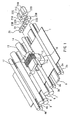
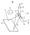
- Fig. 1 is a perspective view of a configuration of a hologram forming apparatus according to the embodiment of the invention.
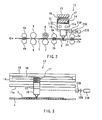
- Fig. 2 is a partially cutaway front view of the hologram forming apparatus shown in Fig. 1 .
- Fig. 3 is a side view of the hologram forming apparatus shown in Fig. 1 .
- the hologram forming apparatus has: three pairs of cylindrical transport rollers 2a, 2b; 3a, 3b; and 4a, 4b for transporting a sheet-like recording medium 1 in which information is recorded utilizing holography from a supply portion (not shown) to an ejecting portion (not shown); a plate-like guide portion 5 provided in parallel with the transport rollers 2a, 2b and 3a, 3b in the axial direction thereof in a position under the recording medium 1 between the transport rollers 2a, 2b and transport rollers 3a, 3b; and a head 10 provided opposite to the guide portion 5 with the recording medium 1 interposed therebetween for illuminating a part of the recording medium 1 with two beams of recording light for forming a part of an interference pattern to be recorded in the recording medium 1 to thereby record the part of the interference pattern.
- the hologram forming apparatus further has: a cylindrical ultraviolet lamp 6 provided in a position above the recording medium 1 between the transport rollers 3a, 3b and transport rollers 4a, 4b; a cylindrical pinch roller 7 provided under the ultraviolet lamp 6 for holding the recording medium 1 in cooperation with the ultraviolet lamp 6; a cylindrical heat roller 8 provided in a position above the recording medium 1 between the region of the ultraviolet lamp 6 and pinch roller 7 and the region of the transport rollers 4a, 4b; and a cylindrical pinch roller 9 for holding the recording medium 1 in cooperation with the heat roller 8.
- the ultraviolet lamp 6 illuminates the recording medium 1 with ultraviolet light
- the heat roller 8 applies heat to the recording medium 1. They correspond to fixing means according to the invention.
- the hologram forming apparatus further has: two guide shafts 11a, 11b provided in parallel with the transport rollers 2a, 2b and 3a, 3b in the axial direction thereof above the head 10; and a movable portion 12 movable along the guide shafts 11a, 11b under the guidance of the guide shafts 11a, 11b.
- the head 10 is bonded to a lower end face of the movable portion 12 to be moved with the movable portion 12.
- the hologram forming apparatus further has a voice coil motor (hereinafter referred to as "VCM") 13 for moving the movable portion 12 along the guide shafts 11a, 11b.
- VCM 13 has: a VCM yoke 14 provided above the guide shafts 11a, 11b in parallel with the guide shafts 11a, 11b; a VCM yoke 15 provided above the VCM yoke 14 in parallel with the VCM yoke 14 with a predetermined interval therebetween and coupled to the VCM yoke 14 at the ends thereof; a plate-like VCM magnet 16 secured to the bottom surface of the VCM yoke 15; and a voice coil 17 provided around the VCM yoke 14 at a predetermined interval from the outer circumferential surface of the VCM yoke 14.
- the voice coil 17 is bonded to an upper end face of the movable portion 12.
- Fig. 1 omits the VCM yoke 15 and VCM magnet 16.
- the VCM 13 having such a configuration moves the head 10 in parallel with the guide shafts 11a, 11b.
- the VCM 13 constitutes position change means according to the invention for changing the relative positional relationship between the head 10 and recording medium 1.
- the hologram forming apparatus further has: an R light source device 21R for emitting coherent laser light in red (hereinafter represented by “R”); a G light source device 21G for emitting coherent laser light in green (hereinafter represented by “G”); a B light source device 21B for emitting coherent laser light in blue (hereinafter represented by “B”); collimator lenses 22R, 22G, 22B for collimating the laser light emitted by the respective light source devices 21R, 21G, 21B; a dichroic prism 23R upon which light impinges through the collimator lens 22R; a dichroic prism 23G upon which light impinges through the collimator lens 22G; and a reflecting prism 23B upon which light impinges through the collimator lens 22B.
- R an R light source device 21R for emitting coherent laser light in red
- G for emitting coherent laser light in green
- B light source device 21B for emitting coherent laser light in blue
- the reflecting prism 23B reflects B light which has passed through the collimator lens 22B.
- the B light reflected by the reflecting prism 23B impinges upon the dichroic prism 23G sideways.
- the dichroic prism 23G reflects G light which has passed through the collimator lens 22G and transmits the B light from the reflecting prism 23B. Both of the G light reflected by the dichroic prism 23G and the B light transmitted by the dichroic prism 23G impinge upon the dichroic prism 23R sideways.
- the dichroic prism 23R reflects R light which has passed through the collimator lens 22R and transmits the B light and G light from the dichroic prism 23G.
- the hologram forming apparatus further has: a spatial light modulator 24 for spatially modulating each of the beams of light R, G, B from the dichroic prism 23R; and a reflecting prism 25 for reflecting light which has passed through the spatial light modulator 24 to cause it to impinge upon the head 10.
- the spatial light modulator 24 has a multiplicity of pixels arranged in the form of a grid and can select the direction of polarization of light emitted by each of the pixels to spatially modulate light by means of the different polarizing directions.
- the spatial light modulator 24 specifically has a configuration similar to that of a liquid crystal display element utilizing rotatory polarization of liquid crystals excluding the polarizing plate.
- the spatial light modulator 24 is adapted to rotate the polarizing direction of each pixel at +90° when it is off and not to rotate the polarizing direction when it is on.
- ferroelectric liquid crystals having a high response speed (on the order of microsecond) may be used as the liquid crystals of the spatial light modulator 24. This allows recording at a high speed.
- the head 10 has: an objective lens 32 provided in a face-to-face relationship with the recording medium 1; an actuator 33 movable in the direction of the thickness of the recording medium 1 and the transporting direction of the same; and a double optically rotating plate 34, an S-polarized hologram 35, a beam splitter 37, a convex lens 38, a cylindrical lens 39 and a quadruple photodetector 40 which are disposed on the side of the objective lens 32 opposite to the recording medium 1 in the order listed that is the order of their closeness to the objective lens 32.
- the beam splitter 37 has a half-reflecting surface 37a provided at an angle of 45° to the direction of the optical axis of the objective lens 32 for reflecting a part of the quantity of light incident thereupon and for transmitting a part of the quantity of light.
- the light from the reflecting prism 25 in Fig. 1 impinges upon the beam splitter 37 sideways, and a part of the quantity of light is reflected by the half-reflecting surface 37a to impinge upon the S-polarized hologram 35.
- the S-polarized hologram 35 has a lens function to converge only S-polarized light.
- P-polarized light in the form of parallel beams from the beam splitter 37 impinges upon the S-polarized hologram 35
- the light passes through the S-polarized hologram 35 in the form of parallel beams to be collected by the objective lens 32 and projected upon the recording medium 1.
- the light convergingly passes through the recording medium 1 and converges to a minimum diameter at the further side of the recording medium 1.
- S-polarized light in the form of parallel beams from the beam splitter 37 impinges upon the S-polarized hologram 35
- the light is slightly converged by the S-polarized hologram 35 and then collected by the objective lens 32 to be projected upon the recording medium 1.
- the light temporarily converges to a minimum diameter before the recording medium 1 and thereafter divergingly passes through the recording medium 1.
- S-polarized light is linear polarized light whose polarizing direction is perpendicular to the plane of incidence (the plane of Fig. 4 ), and P-polarized light is linear polarized light whose polarizing direction is in parallel with the plane of incidence.
- the double optically rotating plate 34 has: an optically rotating plate 34L provided on the left side of the optical axis in Fig. 4 ; and an optically rotating plate 34R provided on the right side of the optical axis in Fig. 4 .
- the optically rotating plate 34L rotates a polarizing direction at -45°
- the optically rotating plate 34R rotates a polarizing direction at +45°.
- Information for tracking servo and address information is recorded in the form of embossed pits 5a arranged on the lower end of the guide portion 5 in the moving direction of the head 10.
- the illuminated light converged by the objective lens 32 to a minimum diameter at the further side of the recording medium 1 is reflected by the lower end of the guide portion 5 to become return light modulated by the embossed pits 5a, to impinge upon the objective lens 32.
- the return light passes through the double optically rotating plate 34 and the S-polarized hologram 35 to impinge upon the beam splitter 37, and a part of the quantity of light is transmitted by the half-reflecting surface 37a to impinge upon the quadruple photodetector 40 after passing through the convex lens 38 and cylindrical lens 39.
- the quadruple photodetector 40 has four light-receiving portions 40a through 40d divided by a division line 40A in parallel with the moving direction of the head 10 and a division line 40B orthogonal thereto.
- the cylindrical lens 39 is provided such that the central axis of the cylindrical surface thereof is at an angle of 45° to the division lines 40A and 40B of the quadruple photodetector 40.
- the recording medium 1 is formed by stacking hologram layers 52B, 52G and 52R in which information is recorded in the form of a three-dimensional interference pattern using volume holography and a protection layer 53 in the order listed on one surface of a transparent base material 51.
- Each of the hologram layers 52B, 52G and 52R is formed of a hologram material whose optical characteristics such as the refractive index, permittivity and reflectivity change depending on the intensity of light illuminating the same.
- the optical characteristics of the hologram layer 52B are changed only by B light; the optical characteristics of the hologram layer 52G are changed only by G light; and the optical characteristics of the hologram layer 52R are changed only by R light.
- photopolymers are used as the hologram materials.
- the hologram layers 52B, 52G and 52R may be replaced with a single hologram layer whose optical characteristics change depending on the light used.
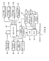
- Fig. 6 is a block diagram of a circuit configuration of the hologram forming apparatus according to the present embodiment.
- the hologram forming apparatus has: a detection circuit 61 for detecting a focus error signal FE, a tracking error signal TE and a reproduction signal RF from an output signal of the head 10; a focus servo circuit 62 for performing focus servo by driving the actuator 33 in the head 10 based on the focus error signal FE detected by the detection circuit 61 to move the objective lens 32 in the direction of the thickness of the recording medium 1; and a tracking servo circuit 63 for performing tracking servo by driving the actuator 33 in the head 10 based on the tracking error signal TE detected by the detection circuit 61 to move the objective lens 32 in the direction in which the recording medium 1 is transported.
- the hologram forming apparatus has a signal processing circuit 64 for reproducing a basic clock and determining an address from the reproduction signal RF from the detection circuit 61 and has a controller 65 for controlling the hologram forming apparatus as a whole.
- the controller 65 receives input of the basic clock and address information outputted by the signal processing circuit 64 and controls the VCM 13, R light source device 21R, G light source device 21G, B light source device 21B, spatial light modulator 24, transport device 20, ultraviolet lamp 6 and heat roller 8.
- the transport device 20 is a device for transporting the recording medium 1 from a supply portion (not shown) to an ejecting portion (not shown) and includes transport rollers 2a, 2b; 3a, 3b; and 4a, 4b.
- the transport device 20 constitutes position change means according to the invention.
- the controller 65 has a function of receiving input of three-dimensional image information 67 from the outside and calculating a modulation pattern for information light for recording based on the three-dimensional image information 67.
- the actuator 33, detection circuit 61, focus servo circuit 62 and tracking servo circuit 63 correspond to position control means according to the invention.
- the hologram forming apparatus further has an operating portion 66 for providing various instructions to the controller 65.
- the controller 65 has a CPU (central processing unit), a ROM (read only memory) and a RAM (random access memory), and the CPU executes programs stored in the ROM using the RAM as a work area to achieve the functions of the controller 65.
- Fig. 7 is a block diagram showing a configuration of the detection circuit 61 for detecting the focus error signal FE, tracking error signal TE and reproduction signal RF based on the output of the quadruple photodetector 40.
- the detection circuit 61 has: an adder 41 for adding the output of each of the diagonal light-receiving portions 40a and 40d of the quadruple photodetector 40; an adder 42 for adding the output of each of the diagonal light-receiving portions 40b and 40c of the quadruple photodetector 40; a subtracter 43 for calculating the difference between the outputs of the adders 41 and 42 to generate the focus error signal FE based on a stigmatic method: an adder 44 for adding the output of each of the light-receiving portions 40a and 40b of the quadruple photodetector 40 which are adjacent to each other in the moving direction of the head 10; an adder 45 for adding the output of each of the light-receiving portions 40c and 40
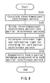
- Fig. 8 is a flow chart of an operation of the hologram forming apparatus according to the present embodiment
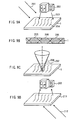
- Figs. 9A through 9D are illustrations of a method for forming a hologram according to the present embodiment and a method for reproducing a three-dimensional image from a hologram formed thereby.
- the controller 65 first calculates a three-dimensional interference pattern for generating reproduction light associated with a desired three-dimensional image when the recording medium 1 is illuminated with reference light for reproduction (step S101).
- the technique of computerized holography is applied to reference light 201 and object light 203 from a three-dimensional image 202 to be represented which are assumed to be present as shown in Fig. 9A to calculate a three-dimensional interference pattern 204 which will be formed in the recording medium 1 when the recording medium 1 is illuminated with the reference light 201 and object light 203.
- the reference light in Fig. 9A is assumed to be parallel light, the reference light may be divergent light or convergent light.
- the calculation of the three-dimensional interference pattern 204 is specifically carried out as follows. First, on a predetermined plane on which a coordinate is represented by (x, y), amplitude and phase information of the reference light 201 and object light 203 is respectively represented by R 1 (x, y) and O 1 (x, y) and expressed by the following equations.
- r 1 and o 1 represent amplitudes
- ⁇ R1 and ⁇ 01 represent phases.
- I 1 x y r 1 x y 2 + o 1 x y 2 + 2 ⁇ r 1 x y ⁇ o 1 x y ⁇ cos ⁇ R ⁇ 1 - ⁇ O ⁇ 1
- the three-dimensional interference pattern 204 in the recording medium 1 can be calculated by calculating intensity of light I 1 (x, y) for each of a plurality of planes assumed to be present in the recording medium 1.
- the amplitude and phase information O 1 (x, y) of the object light 203 may be calculated based on the information of the three-dimensional image to be reproduced (e.g., three-dimensional image data to be processed by a computer).
- the amplitude and phase information R 1 (x, y) of the reference light 201 may be determined in advance.
- the controller 65 divides the three-dimensional interference pattern 204 into partial interference patterns 205 (step S102).
- the partial interference patterns 205 are parts of the three-dimensional interference pattern 204 as shown in Fig. 9B and are three-dimensional interference patterns in regions in the recording medium 1 where two beams of recording light emitted by the head 10 overlap.
- reference light for recording one of the two beams of recording light
- information light for recording one of the two beams of recording light.
- the controller 65 calculates the reference light for recording and information light for recording for each of the partial interference patterns 205 (step S103). For example, this is specifically performed as described below.
- the amplitude and phase information of the reference light for recording is represented by R 2 (x, y)
- the amplitude and phase information of the information light for recording is represented by and O 2 (x, y), which are respectively expressed by the following equations.
- r 2 and O 2 represent amplitudes
- ⁇ R2 and ⁇ O2 represent phases.
- the calculation is simple if the reference light for recording is uniform light or light which is in a constant relationship with the information light for recording.
- the controller 65 calculates a modulation pattern that provides desired reference light for recording and information light for recording, and controls the spatial light modulator 24 using the modulation pattern to illuminate the recording medium 1 with reference light 206 for recording and information light 207 for recording as shown in Fig. 9C .
- each of the partial interference patterns 205 is actually recorded in the recording medium 1, and partial holograms associated with the respective partial interference patterns 205 (hereinafter referred to as "partial holograms”) are sequentially formed (step S104) to form a hologram as a whole.
- the hologram thus formed is a transmission type (Fresnel type) hologram.
- the hologram 211 may be illuminated with reference light for reproduction in the same direction as the reference light 201 in Fig. 9A , or may be illuminated with reference light 212 for reproduction in the direction opposite to that of the reference light 201 as shown in Fig. 9D .
- the hologram 211 is illuminated with the reference light for reproduction in the same direction as the reference light 201, the three-dimensional image 202 will appear as a virtual image above the hologram 211 when viewed from below the hologram 211 in Fig. 9D .
- Fig. 9A the reference light for reproduction in the same direction as the reference light 201
- the hologram forming apparatus is capable of forming a hologram from which a color three-dimensional image can be reproduced. Therefore, in the present embodiment, holograms associated with R, G and B three-dimensional images that form a color three-dimensional image are respectively formed in the hologram layers 52R, 52G and 52B of the recording medium 1. In the present embodiment, specifically, a hologram in each of R, G and B colors is formed by forming a partial hologram in each of R, G and B colors on a time division basis.
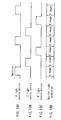
- the light source devices 21R, 21G and 21B respectively provided for R, G and B colors and the spatial light modulator 24 are controlled as shown in Figs. 10A through 10D .
- the spatial light modulator 24 is driven repeatedly in a modulation pattern for the partial hologram associated with the R image, a modulation pattern for the partial hologram associated with the G image and a modulation pattern for the partial hologram associated with the B image at a constant cycle.
- the R light source device 21R emits R light at timing when the spatial light modulator 24 is driven in the modulation pattern associated with the partial hologram for the R image.
- Fig. 10A the spatial light modulator 24 emits R light at timing when the spatial light modulator 24 is driven in the modulation pattern associated with the partial hologram for the R image.
- the G light source device 21G emits G light at timing when the spatial light modulator 24 is driven in the modulation pattern associated with the partial hologram for the G image and, as shown in Fig. 10C , the B light source device 21B emits B light at timing when the spatial light modulator 24 is driven in the modulation pattern associated with the partial hologram for the B image.
- each of the light source devices 21R, 21G and 21B emits S-polarized light.
- the R light emitted by the R light source device 21R is collimated by the collimator lens 22R and reflected by the dichroic prism 23R to impinge upon the spatial light modulator 24.
- the G light emitted by the G light source device 21G is collimated by the collimator lens 22G, reflected by the dichroic prism 23G and transmitted by the dichroic prism 23R to impinge upon the spatial light modulator 24.
- the B light emitted by the B light source device 21B is collimated by the collimator lens 22B, reflected by the reflecting prism 23B and transmitted by the dichroic prisms 23G and 23R to impinge upon the spatial light modulator 24.
- the light spatially modulated by the spatial light modulator 24 is reflected by the reflecting prism 25 to impinge upon the head 10.
- the light spatially modulated by the spatially light modulator 24 is light which is set at S-polarization or P-polarization depending on pixels.
- A-polarized light is linear polarized light obtained by rotating the polarizing direction of S-polarized light at -45° or by rotating the polarizing direction of P-polarized light at +45°
- B-polarized light is linear polarized light obtained by rotating the polarizing direction of S-polarized light at +45° or by rotating the polarizing direction of P-polarized light at -45°.
- the polarizing directions of the A-polarized light and B-polarized light are orthogonal to each other.
- the P-polarized light included in the light incident upon the S-polarized hologram 35 passes through the S-polarized hologram 35 as it is in the form of parallel beams. In the present embodiment, this light is the reference light for recording.
- the reference light for recording impinges upon the double optically rotating plate 34.
- a part of the light which has passed through the optically rotating plate 34L is subjected to rotation of the polarizing direction at -45° to become B-polarized light
- a part of the light which has passed through the optically rotating plate 34R is subjected to rotation of the polarizing direction at +45° to become A-polarized light.
- the reference light for recording is collected by the objective lens 32 to illuminate the recording medium 1. It convergingly passes through the recording medium 1 and converges to a minimum diameter at the further side of the recording medium 1.
- the S-polarized light included in the light incident upon the S-polarized hologram 35 is slightly converged by the S-polarized hologram 35.
- this light is the information light for recording.
- the information light for recording impinges upon the double optically rotating plate 34. A part of the light which has passed through the optically rotating plate 34L is subjected to rotation of the polarizing direction at -45° to become A-polarized light, and a part of the light which has passed through the optically rotating plate 34R is subjected to rotation of the polarizing direction at +45° to become B-polarized light.
- the information light for recording is collected by the objective lens 32 to illuminate the recording medium 1. It temporarily converges to a minimum diameter before the recording medium 1 and thereafter divergingly passes through the recording medium 1.
- the reference light for recording and the information light for recording illuminate the recording medium 1 on the same side thereof such that the optical axes of those beams of light are located on the same line.
- Figs. 12 and 13 are illustrations of states of light in the vicinity of the recording medium 1.
- the reference number 71 represents P-polarized light
- the reference number 72 represents S-polarized light
- the reference number 73 represents A-polarized light
- the reference number 74 represents B-polarized light.
- reference light for recording which has passed through the optically rotating plate 34R and information light for recording which has passed through the optically rotating plate 34L interfere with each other because they are both A-polarized light, and the pattern of the interference is recorded in the recording medium 1.
- Fig. 12 reference light for recording which has passed through the optically rotating plate 34R and information light for recording which has passed through the optically rotating plate 34L interfere with each other because they are both A-polarized light, and the pattern of the interference is recorded in the recording medium 1.
- Fig. 12 reference light for recording which has passed through the optically rotating plate 34R and information light for recording which has passed through the optically rotating plate 34L interfere with each other because they are both A-polarized light, and the pattern of the interference
- reference light for recording which has passed through the optically rotating plate 34L and information light for recording which has passed through the optically rotating plate 34R interfere with each other because they are both B-polarized light, and the pattern of the interference is recorded on the recording medium 1.
- partial holograms are formed in the recording medium 1.
- a partial hologram is formed on the hologram layer 52R in Fig. 5 .
- a partial hologram is formed on the hologram layer 52G in Fig. 5 .
- a partial hologram is formed on the hologram layer 52B in Fig. 5 .
- the reference light for recording is reflected by the lower end of the guide portion 5 and is turned into return light which has been modulated by the embossed pits 5a.
- No interference occurs between A-polarized return light associated with the reference light for recording which has passed through the optically rotating plate 34R and B-polarized information light for recording which has passed through the optically rotating plate 34R because they cross each other.
- no interference occurs between B-polarized return light associated with the reference light for recording which has passed through the optically rotating plate 34L and A-polarized information light for recording which has passed through the optically rotating plate 34L because they cross each other.
- the recording medium 1 is transported by the transport device 20, and the transport device 20 keeps the recording medium 1 stationary while the head 10 forms partial holograms for one line. In such a period, the head 10 sequentially forms partial holograms while moving from one end to the other end of the range where the partial holograms are to be formed.
- the transport device 20 moves the recording medium 1 by a predetermined line interval and thereafter stops the recording medium 1. Partial holograms for the next one line are formed through the same operation as that described above. Such an operation is repeated to form a complete hologram.
- the reference light for recording is reflected by the lower end of the guide portion 5 to be turned into return light modulated by the embossed pits 5a.
- the return light is collimated by the objective lens 32 and passes through the double optically rotating plate 34 to be turned into S-polarized light which in turn passes through the S-polarized hologram 35 and is slightly converged. Thereafter, the S-polarized light impinges upon the beam splitter 37, and a part of the quantity of light is transmitted by the half-reflecting surface 37a to impinge upon the quadruple photodetector 40 after passing through the convex lens 38 and cylindrical lens 39.
- the detection circuit 61 detects the focus error signal FE, tracking error signal TE and reproduction signal RF based on the output of the quadruple photodetector 40. Based on the focus error signal FE, the focus servo circuit 62 performs focus servo to always keep the reference light for recording and the information light for recording in a constant positional relationship with the recording medium 1 in the direction of the thickness of the recording medium 1. Based on the tracking error signal TE, the tracking servo circuit 63 performs tracking servo to always keep the reference light for recording and the information light for recording in a constant positional relationship with the recording medium 1 in the transporting direction of the recording medium 1. The signal processing circuit 64 reproduces the basic clock and determines addresses based on the reproduction signal RF.
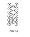
- Fig. 14 shows an example of an arrangement of partial holograms in each of R, G and B colors.
- the circles indicated by reference symbols R, G and B represent partial holograms in R, G and B colors, respectively.
- a region of the recording medium 1 having holograms formed thereon reaches the position of the ultraviolet lamp 6 which illuminates the region with ultraviolet light, and the region further reaches the position of the heat roller 8 which applies heat to the region to fix the partial interference patterns (partial holograms) recorded by the head 10.
- the recording medium 1 becomes a stabilized hologram which is in turn transported by the transport device 20 and ejected from the ejecting portion.
- a reproducing apparatus 300 shown in Fig. 15 has a configuration similar to that of an overhead projector (hereinafter referred to as "OHP").
- the reproducing apparatus 300 has: a cubic main body portion 301; an arm portion 302 extending upward from the rear surface of the main body portion 301; and a mirror portion 303 coupled to the upper end of the arm portion 302.
- the top surface region of the main body portion 301 is formed by a transparent member such as glass, and the top surface serves as a mounting surface 304 on which a hologram 211 is mounted.
- a light source device 311 which emits light to serve as reference light; and an optical system 312 for forming predetermined reference light 313 in the form of parallel light or the like by, for example, collecting the light emitted by the light source device 311 to illuminate the hologram 211 mounted on the mounting surface 304 from below the same.
- the light source device 311 emits laser light in each of R, G and B colors or emits white light.
- the reproducing apparatus is to reproduce monochromatic three-dimensional images, for example, it emits laser light having a predetermined wavelength.
- the reference light 313 illuminates the hologram 211 mounted on the mounting surface 304 from below to generate reproduction light 315 which travels upward from the hologram 211.
- the mirror portion 303 has a mirror 305 for reflecting the reproduction light 315 generated at the hologram 211 toward the front side of the reproducing apparatus 300.
- the reproduction light 315 generated at the hologram 211 is reflected by the mirror 305 toward the front side of the reproducing apparatus 300 to form a real three-dimensional image 202. Therefore, a viewer can view the three-dimensional image 202 in front of the reproducing apparatus 300.
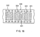
- a hologram 320 shown in Fig. 16 has a configuration like a movie film. That is, the hologram 320 as a whole is in the form of a band which is formed with a multiplicity of perforations (holes for feeding) 321 on both sides thereof.
- a plurality of rectangular hologram portions 322 are formed in the longitudinal direction between the perforations 321 on both sides.
- Each of the hologram portions 322 corresponds to one frame of a move film and has a three-dimensional interference pattern recorded therein which is associated with one three-dimensional image.
- the hologram 320 shown in Fig. 16 is formed as follows using the hologram forming apparatus according to the present embodiment. First, there is provided a film-like recording medium having perforations 321 on both sides thereof and having a hologram layer at least in regions where hologram portions 322 are formed. Partial holograms are sequentially formed using the hologram forming apparatus with the recording medium transported in the longitudinal direction thereof, and each of the hologram portions 322 is formed by a plurality of partial holograms.
- a reproducing apparatus 330 shown in Fig. 17 has a configuration like that of a projector.
- the reproducing apparatus 330 has: a driving device (not shown) for moving the hologram 320 intermittently in the longitudinal direction; a light source device 331 for emitting light to serve as reference light; an optical system 332 for forming predetermined reference light 333 in the form of parallel light or the like by, for example, collecting the light emitted by the light source device 331 to illuminate the hologram portions 322 of the hologram 320; and a reflection type screen 336 for reflecting reproduction light 335 generated by the hologram portions 322 when illuminated with the reference light 333.
- the light source device 331 it is similar to the light source device 311 of the reproducing apparatus 300 shown in Fig. 15 .
- the hologram 320 is intermittently driven by the driving device, and a hologram portion 322 is illuminated with reference light 333 only during a period when the hologram 320 is stopped.
- the intermittent illumination with the reference light 333 can be performed by causing the light source device 331 to emit light intermittently or by using a shutter.
- the hologram portion 322 generates reproduction light 335 when illuminated with the reference light 333, and the reproduction light 335 is reflected by the screen 336 toward the front side of the screen 336 to form a real three-dimensional image 337. Therefore, a viewer can view the three-dimensional image 337 in front of the screen 336.
- a moving three-dimensional image can be reproduced, for example, by associating each of the hologram portions 322 of the hologram 320 with a three-dimensional image corresponding to each frame of a motion picture as in the case of a movie.
- a hologram is formed by illuminating a part of the recording medium 1 with reference light for recording and information light for recording using the head 10 to record a part of an interference pattern for generating reproduction light associated with a desired three-dimensional image when illuminated with reference light for reproduction, and by repeating the operation of recording a part of an interference pattern a plurality of times while changing the relative positional relationship between the head 10 and recording medium 1.
- a calculation is made to obtain a plurality of beams of recording light for forming a part of an interference pattern for generating reproduction light associated with a desired three-dimensional image when illuminated with reference light for reproduction; a modulation pattern that provides such beams of recording light is calculated; beams of recording light modulated in the modulation pattern are generated; and the recording medium 1 is illuminated with the beams of recording light always in the same direction. It is therefore possible to form a hologram for reproducing a three-dimensional image free of limitations placed by the reference light for reproduction.
- holograms in various shapes can be formed.
- a hologram having the ultimate shape may be formed as a combination of several fragments each of which is formed using the hologram forming apparatus according to the present embodiment.
- the recording medium 1 that allows recording of a three-dimensional interference pattern is used, and a three-dimensional interference pattern is recorded on the recording medium 1. This makes it possible to utilize Bragg diffraction effectively and to thereby provide improved diffracting efficiency and improved rendering capability in representing a three-dimensional image.
- the recording medium 1 is formed in a sheet-like configuration and is illuminated with reference light for recording and information light for recording on the same side thereof such that the optical axes of those beams of light are located on the same line. This makes it possible to illuminate the recording medium 1 with reference light for recording and information light for recording using a single head 10 and to provide the optical system of the head 10 with a more compact configuration.
- reference light for recording reflected by the guide portion 5 is used to control the positions of the reference light for recording and the information light for recording relative to the recording medium 1. This makes it possible to form a hologram with high accuracy.
- a hologram having arbitrary three-dimensional image information recorded therein can be easily formed similarly to printing using a normal printer. It is therefore possible to copy a hologram easily and to form a great number of holograms having the same three-dimensional image information recorded therein.
- a hologram forming apparatus and a reproducing apparatus for reproducing a three-dimensional image from a hologram according to the present embodiment are provided in a remote location, it is possible to form a hologram using the hologram forming apparatus by transmitting three-dimensional image information to the remote location using the internet or the like and to reproduce a three-dimensional image from the hologram thus formed. It is therefore possible to form holograms having three-dimensional image information with the same quality and to reproduce three-dimensional images with the same quality in any place.
- beams of recording light are calculated based on three-dimensional image information, e.g., three-dimensional image data to be processed by a computer.
- a hologram can be easily corrected by correcting the three-dimensional image data. Therefore, when a final hologram is to be formed with appropriate corrections added thereto, the embodiment makes it possible to form the final hologram more easily with a reduced cost compared to methods wherein a hologram is formed by causing interference between object light from an existing object and reference light.
- a hologram can be formed based on three-dimensional image information even for an object which does not exist or which is too large, and an image can be easily formed with characters representing a title or the like or various visual effects added thereon, which makes it possible to create advertisements and magazine front pages that give stronger impression.
- a hologram in the form of a thin sheet can be formed, it is possible to form a hologram which has high portability like conventional OHP sheets and which can be filed similarly to a sheet of paper. Further, a presentation can be carried out using three-dimensional images with ease of operation similar to that of a conventional OHP and OHP sheets by forming sheet-like holograms and using a simple reproducing apparatus having a configuration similar to that of an OHP as shown in Fig. 15 . According to the present embodiment, a thick recording medium can be used to form a hologram for reproducing a three-dimensional image therein.
- the recording medium 1 to allow recording of a three-dimensional interference pattern is used, and a three-dimensional interference pattern is recorded in the recording medium 1. It is therefore possible to perform multiplex recording of a plurality of three-dimensional interference patterns in the recording medium 1 by combining beams of reference light and object light on an assumption that there are a plurality of beams of reference light incident at different angles as reference light for reproduction and that there are beams of object light from different three-dimensional images originating from the respective beams of the reference light. This makes it possible to form a hologram that allows reproduction of different three-dimensional images depending on the incident angle of the reference light for reproduction.
- a hologram may be formed on an assumption that there is a plurality of parallel beams at different angles of incidence as reference light for reproduction, and three-dimensional images may be reproduced from the hologram using sun beams as reference light for reproduction, which makes it possible to form a hologram that allows reproduction of different three-dimensional images depending on the time zones of a day.
- the spatial light modulator 24 of the present embodiment is provided between the dichroic prism 23R and reflecting prism 25 shown in Fig. 1
- the spatial light modulator 24 may alternatively be provided between the beam splitter 37 and S-polarized hologram 35 in the head 10 or on the side of the incident surface of the beam splitter 37.
- spatial light modulators to be respectively and exclusively used for R, G and B images may be provided between the collimator lens 22R and dichroic prism 23R, between the collimator lens 22G and dichroic prism 23G and between the collimator lens 22B and reflecting prism 23B, respectively.
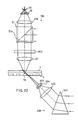
- FIG. 18 is a perspective view of a configuration of a hologram forming apparatus according to the first example not according to the invention.
- the hologram forming apparatus of the first example not according to the invention does not have the spatial light modulator 24 as provided in the first embodiment.
- a head 410 in place of the head 10 of the embodiment.
- Fig. 19 is an illustration of a configuration of the head of the first example not according to the invention.
- the head 410 of the first example not according to the invention has: an objective lens 32 provided opposite to a recording medium 1; an actuator (not shown) capable of moving the objective lens 32 in the direction of the thickness of the recording medium 1 and a transporting direction of the recording medium 1; and a spatial light modulator 411, a beam splitter 37, a convex lens 418, a cylindrical lens 39 and a quadruple photodetector 40 which are disposed on the side of the objective lens 32 opposite to the recording medium 1 in the order listed that is the order of their closeness to the objective lens 32.
- the head 410 further has: a mirror 412 disposed in the traveling direction of light that is incident from the reflecting prism 25 in Fig. 18 and transmitted by a half-reflecting surface 37a of the beam splitter 37; and a convex lens 413, a concave lens 414 and a cylindrical lens 415 which are disposed in the traveling direction of light reflected by the mirror 412 in the order listed that is the order of their closeness to the mirror 412.
- Light emitted by the cylindrical lens 415 impinges upon the recording medium 1 such that the center (optical axis) thereof is at an angle of 45° to the surface of the recording medium 1 and crosses light from the objective lens 32 in the recording medium 1.
- Light emitted by the cylindrical lens 415 is narrowed to a minimum thickness in the recording medium 1.
- the spatial light modulator 411 in the the first example not according to the invention has a great number of pixels arranged in the form of a grid and is capable of spatially modulating light on the basis of light intensity by selecting a light transmitting state or blocking state for each of the pixels.
- the spatial light modulator 411 is driven by the controller 65 shown in Fig. 6 .
- the head 410 of the first example not according to the invention light incident upon the head 410 impinges upon the beam splitter 37 sideways; a part of the quantity of light is reflected by the half-reflecting surface 37a; and a part of the quantity of light is transmitted by the half-reflecting surface 37a.
- the light reflected by the half-reflecting surface 37a impinges upon the spatial light modulator 411 which spatially modulates the light.
- this light serves as information light for recording.
- the information light for recording is collected by the objective lens 32 to impinge upon the recording medium 1, and the light convergingly passes through the recording medium 1 and converges to a minimum diameter at the further side of the recording medium 1.
- this light serves as reference light for recording.
- the reference light for recording crosses the information light for recording from the objective lens 32 inside the recording medium 1.
- a three-dimensional interference pattern is recorded in the recording medium 1 as a result of interference between the information light for recording and the reference light for recording.
- the interference pattern serves as a partial interference pattern to form a partial hologram.
- the partial hologram has a configuration in the form of a circular plate. Partial holograms are sequentially formed by moving the head 410 similarly to the the first example not according to the invention embodiment.
- Fig. 20 illustrates a state of partial holograms 420 formed in the recording medium 1 in such a manner.
- a plurality of partial holograms 420 in the form of layers are formed on one another in the recording medium 1.
- the controller 65 calculates the reference light for recording and the information light for recording on an assumption that there are partial interference patterns in the partial holograms in the form of layers.
- the information light for recording is turned into return light which has been reflected by the lower end of the guide portion 5 and modulated by the embossed pits 5a.
- the return light is collimated by the objective lens 32 to pass through the spatial light modulator 411, and is thereafter incident upon the beam splitter 37.
- a part of the quantity of light is transmitted by the half-reflecting surface 37a and passes through the convex lens 418 and cylindrical lens 39 to impinge upon the quadruple photodetector 40.
- the detection circuit 61 Based on the output of the quadruple photodetector 40, the detection circuit 61 detects a focus error signal FE, a tracking error signal TE and a reproduction signal RF.
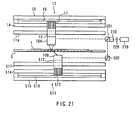
- Fig. 21 is a side view of the hologram forming apparatus according to the first example not according to the invention.
- This hologram forming apparatus is provided with an upper head portion 10A in place of the head 10 of the embodiment.
- the hologram forming apparatus further has: a lower head portion 10B provided under the guide portion 5; two guide shafts 511 provided above the lower head portion 10B in parallel with the axial direction of the transport rollers 2a, 2b and 3a, 3b; and a movable portion 512 movable along the guide shafts 511 under the guidance of the guide shafts 511.
- the lower head portion 10B is bonded to an upper end face of the movable portion 512 to be moved with the movable portion 512.
- the hologram forming apparatus has a VCM 513 for moving the movable portion 512 along the guide shafts 511.
- the VCM 513 has a configuration similar to that of the VCM 13.
- the VCM 513 has: a VCM yoke 514 provided under the guide shafts 511 in parallel with the guide shafts 511; a VCM yoke 515 provided under the VCM yoke 514 in parallel with the VCM yoke 514 with a predetermined interval therebetween and coupled to the VCM yoke 514 at the ends thereof; a plate-like VCM magnet 516 secured to the top surface of the VCM yoke 515; and a voice coil 517 provided around the VCM yoke 514 at a predetermined interval from the outer circumferential surface of the VCM yoke 514.
- the voice coil 517 is bonded to a lower end face of the movable portion 512.
- the VCM 513 having such a configuration moves the lower head portion
- the upper head portion 10A and the lower head portion 10B correspond to the head according to the invention
- the VCM 13 and the VCM 513 correspond to the position change means according to the invention.
- the hologram forming apparatus further has: a beam splitter 501 upon which light from the reflecting prism 25 in Fig. 1 impinges, which transmits a part of the quantity of light to cause it to impinge upon the upper head portion 10A and which reflects a part of the quantity of light downward; and a reflecting prism 502 for reflecting the light reflected by the beam splitter 501 to cause it to impinge upon the lower head portion 10B.
- Fig. 22 is an illustration of a configuration of the upper head portion 10A and the lower head portion 10B.
- the upper head portion 10A has a configuration obtained by deleting the mirror 412, convex lens 413, concave lens 414 and cylindrical lens 415 from the head 410 shown in Fig. 19 .
- the lower head portion 10B has: a prism 521 for emitting light from the reflecting prism 502 in Fig. 21 upward at a refracting angle of 45°; and a convex lens 523, a concave lens 524 and a cylindrical lens 525 which are disposed in the traveling direction of the light emitted by the prism 521 in the order listed which is the order of their closeness to the prism 521.
- Light emitted by the cylindrical lens 525 impinges upon the recording medium 1 from below such that the center (optical axis) thereof is at an angle of 45° to the surface of the recording medium 1 and crosses light from the objective lens 32 in the recording medium 1.
- Light emitted by the cylindrical lens 525 is narrowed to a minimum thickness in the recording medium 1.
- the VCM 13 and the VCM 513 cooperate under the control of the controller 65 shown in Fig. 6 to establish a constant relative positional relationship between the light from the objective lens 32 and the light from the cylindrical lens 525.
- the beam splitter 37 In the second example not according to the invention, light incident upon the upper head portion 10A impinges upon the beam splitter 37 sideways, and a part of the quantity of light is reflected by the half-reflecting surface 37a.
- the light reflected by the half-reflecting surface 37a impinges upon the spatial light modulator 411 to be spatially modulated by the spatial light modulator 411.
- this light serves as information light for recording.
- the information light for recording is collected by the objective lens 32 to be projected upon the recording medium 1, and the light convergingly passes through the recording medium 1 and converges to a minimum diameter at the further side of the recording medium 1.
- light incident upon the lower head portion 10B is refracted by the prism 521 and passes through the convex lens 523 and concave lens 524 sequentially to reduce the diameter of the beam of light.
- the light is converged by the cylindrical lens 525 only in the direction of the optical axis of the objective lens 32 into a beam of light having a flat configuration which in turn impinges upon the recording medium 1.
- this light serves as reference light for recording.
- the reference light for recording crosses the information light for recording from the objective lens 32 inside the recording medium 1.
- a three-dimensional partial interference pattern is recorded in the recording medium 1 as a result of interference between the information light for recording and the reference light for recording to form a partial hologram.
- the partial hologram has a configuration in the form of a circular plate similar to that in the first example not according to the invention.
- the partial hologram is a reflection type (Lippmann type) hologram. Partial holograms are sequentially formed by moving the upper head portion 10A and the lower head portion 10B to form a complete hologram.
- the hologram is a reflection type hologram.
- the second example not according to the invention thus makes it possible to form a reflection type hologram.
- a reflection type hologram when the hologram is illuminated with reference light for reproduction, reproduction light is produced on the same side thereof as that illuminated with the reference light, and a viewer can view a three-dimensional image reproduced by the reproduction light.
- the present invention is not limited to the above-described embodiment and examples.
- focus servo and tracking servo are performed in the embodiment and examples, it may be sufficient to perform focus servo only, for example, when the head is moved with only a slight run-out.
- reference light for reproduction and reference light for recording are different from each other
- the same light may be used as reference light for reproduction and reference light for recording as a special case.
- object light assumed in association with a three-dimensional image to be displayed may be used as it is as information light for recording, which facilitates calculations of reference light for recording and information light for recording.
- a hologram is formed by performing a plurality of times the operation of illuminating a part of a recording medium on which information is recorded utilizing holography with a plurality of beams of recording light that forms a part of an interference pattern for generating reproduction light associated with a desired three-dimensional image when illuminated with reference light for reproduction to thereby record the part of the interference pattern while changing the relative positional relationship between the recording medium and the beams of recording light. It is therefore possible to form a hologram for reproducing a three-dimensional image easily free from limitations placed by the size of the three-dimensional image to be reproduced, the size of the hologram and reference light for reproduction.
- the apparatus or method for forming a hologram according to the invention is advantageous in that a three-dimensional hologram can be formed by providing a recording medium that allows recording of a three-dimensional interference pattern and by forming a three-dimensional interference pattern.
- the apparatus or method for forming a hologram according to the invention is advantageous in that it is possible to correct the hologram easily by correcting information of a three-dimensional image, which is achieved by spatially modulating at least one of a plurality of beams of recording light in a modulation pattern calculated based on the information of the three-dimensional image.
- the apparatus or method for forming a hologram according to the invention is advantageous in that a hologram is formed with a simple mechanism by forming the recording medium in the form of a sheet and by illuminating the recording medium with a plurality of beams of recording light on the same side thereof.
- the apparatus or method for forming a hologram according to the invention is advantageous in that an optical system for illumination with beams of recording light can be made compact by radiating a plurality of beams of recording light such that the optical axes of the respective beams of recording light are located on the same line.
- the apparatus or method for forming a hologram according to the invention is advantageous in that a hologram is formed with improved accuracy by controlling the positions of a plurality of beams of recording light on the recording medium.
- the apparatus or method for forming a hologram according to the invention is advantageous in that a hologram is formed with improved stability by providing fixing means for fixing an interference pattern recorded in the recording medium.
Landscapes
- Physics & Mathematics (AREA)
- General Physics & Mathematics (AREA)
- Holo Graphy (AREA)
- Optical Head (AREA)
- Testing, Inspecting, Measuring Of Stereoscopic Televisions And Televisions (AREA)
- Optical Recording Or Reproduction (AREA)
Applications Claiming Priority (3)
| Application Number | Priority Date | Filing Date | Title |
|---|---|---|---|
| JP04751798A JP3729477B2 (ja) | 1998-02-27 | 1998-02-27 | ホログラム作成装置および方法 |
| JP4751798 | 1998-02-27 | ||
| PCT/JP1999/000895 WO1999044102A1 (en) | 1998-02-27 | 1999-02-26 | Method and apparatus for forming hologram |
Publications (3)
| Publication Number | Publication Date |
|---|---|
| EP1059574A1 EP1059574A1 (en) | 2000-12-13 |
| EP1059574A4 EP1059574A4 (en) | 2009-04-15 |
| EP1059574B1 true EP1059574B1 (en) | 2012-08-22 |
Family
ID=12777312
Family Applications (1)
| Application Number | Title | Priority Date | Filing Date |
|---|---|---|---|
| EP99906493A Expired - Lifetime EP1059574B1 (en) | 1998-02-27 | 1999-02-26 | Method and apparatus for forming hologram |
Country Status (9)
| Country | Link |
|---|---|
| US (1) | US6366368B1 (enExample) |
| EP (1) | EP1059574B1 (enExample) |
| JP (1) | JP3729477B2 (enExample) |
| KR (1) | KR20010041378A (enExample) |
| CN (1) | CN1292104A (enExample) |
| AU (1) | AU737232B2 (enExample) |
| CA (1) | CA2321535C (enExample) |
| EA (1) | EA002247B1 (enExample) |
| WO (1) | WO1999044102A1 (enExample) |
Families Citing this family (19)
| Publication number | Priority date | Publication date | Assignee | Title |
|---|---|---|---|---|
| US6266167B1 (en) * | 1998-02-27 | 2001-07-24 | Zebra Imaging, Inc. | Apparatus and method for replicating a hologram using a steerable beam |
| JP4843844B2 (ja) * | 1999-12-27 | 2011-12-21 | ソニー株式会社 | 光ヘッド、受発光素子、及び光記録媒体記録再生装置 |
| US6509138B2 (en) * | 2000-01-12 | 2003-01-21 | Semiconductor Research Corporation | Solventless, resistless direct dielectric patterning |
| JP3655819B2 (ja) * | 2000-08-07 | 2005-06-02 | 株式会社オプトウエア | 光情報記録装置および方法、光情報再生装置および方法、ならびに光情報記録再生装置および方法 |
| GB2379850A (en) * | 2001-09-14 | 2003-03-19 | Holographic Imaging Llc | Computation of computer generated holograms |
| US6771402B2 (en) * | 2001-09-28 | 2004-08-03 | Hewlett-Packard Development Company, L.P. | Method and apparatus for generating a hologram |
| US6806982B2 (en) * | 2001-11-30 | 2004-10-19 | Zebra Imaging, Inc. | Pulsed-laser systems and methods for producing holographic stereograms |
| KR100555914B1 (ko) | 2003-11-15 | 2006-03-03 | 주식회사 대우일렉트로닉스 | 홀로그래픽 시스템의 데이터 추출 장치 및 방법 |
| KR100555916B1 (ko) * | 2003-11-17 | 2006-03-03 | 주식회사 대우일렉트로닉스 | 홀로그래픽 롬 시스템의 포커스 서보 제어용 기록 및 재생장치 |
| WO2005078533A1 (en) * | 2004-02-10 | 2005-08-25 | Zebra Imaging, Inc. | Deposition of photosensitive media for digital hologram recording |
| GB2432224A (en) * | 2005-11-15 | 2007-05-16 | Technical Dev & Invest Ltd | Apparatus and method for producing a volume reflection hologram |
| KR100717065B1 (ko) | 2006-05-03 | 2007-05-10 | 삼성전자주식회사 | 홀로그램 기록 재생 장치, 홀로그램 기록 재생 방법 및홀로그램 기록매체 |
| JP2009295233A (ja) * | 2008-06-05 | 2009-12-17 | Tdk Corp | 光記録媒体及び光記録媒体の製造方法 |
| JP5201580B2 (ja) * | 2008-06-06 | 2013-06-05 | 新オプトウエア株式会社 | ホログラム作成装置及びホログラムプリンタ |
| JP2010230911A (ja) * | 2009-03-26 | 2010-10-14 | Tdk Corp | 光学デバイス |
| JP7037797B2 (ja) * | 2017-04-11 | 2022-03-17 | 国立研究開発法人情報通信研究機構 | ホログラム記録装置およびホログラム製造方法 |
| US20230367261A1 (en) * | 2020-12-02 | 2023-11-16 | Korea Electronics Technology Institute | Holographic printing device and method using multiple optical heads |
| US20250004422A1 (en) * | 2021-07-15 | 2025-01-02 | Lg Chem, Ltd. | Holographic Interference Pattern Recording Apparatus and Recording Method Using Same |
| KR102626769B1 (ko) * | 2021-07-30 | 2024-01-18 | 주식회사 홀로랩 | 2축(xy) 스캐닝을 이용한 홀로그램 복제 시스템 |
Citations (3)
| Publication number | Priority date | Publication date | Assignee | Title |
|---|---|---|---|---|
| JPH02163789A (ja) * | 1988-12-19 | 1990-06-25 | Sony Corp | 光ディスク信号記録方法及び装置 |
| JPH03120625A (ja) * | 1989-10-04 | 1991-05-22 | Canon Inc | 情報記録再生装置 |
| EP0467601A2 (en) * | 1990-07-12 | 1992-01-22 | Applied Holographics Corporation | Holographic diffraction grating patterns and methods for creating the same |
Family Cites Families (16)
| Publication number | Priority date | Publication date | Assignee | Title |
|---|---|---|---|---|
| GB1139955A (en) * | 1965-11-22 | 1969-01-15 | Rca Corp | Hologram record pressings |
| US3716286A (en) * | 1969-12-11 | 1973-02-13 | Holotron Corp | Holographic television record system |
| GB1542884A (en) * | 1975-04-01 | 1979-03-28 | Asahi Chemical Ind | Recording and reproducing holograms |
| US4295162A (en) * | 1975-09-11 | 1981-10-13 | Gte Laboratories Incorporated | Reading one-dimensional line image holograms of a video from a disc with a guide track |
| US4206965A (en) * | 1976-08-23 | 1980-06-10 | Mcgrew Stephen P | System for synthesizing strip-multiplexed holograms |
| JPH0812283B2 (ja) | 1987-05-21 | 1996-02-07 | 凸版印刷株式会社 | 回折格子露光装置 |
| JPS6449127A (en) * | 1987-08-19 | 1989-02-23 | Mitsubishi Electric Corp | Multiplex recording and reproducing device based on optical wavelength and optical wavelength multiplex recording medium to be used for the device |
| JPH01238680A (ja) * | 1988-03-18 | 1989-09-22 | Toppan Printing Co Ltd | フルカラーレインボウホログラムの作製方法 |
| JPH04307584A (ja) * | 1991-04-05 | 1992-10-29 | Nippon Telegr & Teleph Corp <Ntt> | 体積多重ホログラフィー装置 |
| US5285438A (en) * | 1991-10-31 | 1994-02-08 | Regents Of The University Of California | Motionless parallel readout head for an optical disk recorded with arrayed one-dimensional holograms |
| JP3651808B2 (ja) | 1993-12-08 | 2005-05-25 | 大日本印刷株式会社 | カラーリップマンホログラムの製造方法 |
| JPH08146862A (ja) * | 1994-11-25 | 1996-06-07 | Asahi Glass Co Ltd | ホログラムの露光方法 |
| JPH08305263A (ja) | 1995-05-08 | 1996-11-22 | Mitsubishi Electric Corp | ホログラム作製装置 |
| KR19990028735A (ko) * | 1995-07-05 | 1999-04-15 | 모리슨 그랜트 | 광 저장 시스템 |
| US6020985A (en) * | 1998-01-30 | 2000-02-01 | Siros Technologies, Inc. | Multilayer reflection microhologram storage in tape media |
| US6147782A (en) * | 1998-05-01 | 2000-11-14 | Siros Technologies, Inc. | Positive unit magnification reflective optics for holographic storage |
-
1998
- 1998-02-27 JP JP04751798A patent/JP3729477B2/ja not_active Expired - Fee Related
-
1999
- 1999-02-26 KR KR1020007009502A patent/KR20010041378A/ko not_active Ceased
- 1999-02-26 WO PCT/JP1999/000895 patent/WO1999044102A1/ja not_active Ceased
- 1999-02-26 CN CN99803385A patent/CN1292104A/zh active Pending
- 1999-02-26 US US09/601,624 patent/US6366368B1/en not_active Expired - Lifetime
- 1999-02-26 EA EA200000886A patent/EA002247B1/ru not_active IP Right Cessation
- 1999-02-26 CA CA002321535A patent/CA2321535C/en not_active Expired - Fee Related
- 1999-02-26 EP EP99906493A patent/EP1059574B1/en not_active Expired - Lifetime
- 1999-02-26 AU AU26406/99A patent/AU737232B2/en not_active Ceased
Patent Citations (3)
| Publication number | Priority date | Publication date | Assignee | Title |
|---|---|---|---|---|
| JPH02163789A (ja) * | 1988-12-19 | 1990-06-25 | Sony Corp | 光ディスク信号記録方法及び装置 |
| JPH03120625A (ja) * | 1989-10-04 | 1991-05-22 | Canon Inc | 情報記録再生装置 |
| EP0467601A2 (en) * | 1990-07-12 | 1992-01-22 | Applied Holographics Corporation | Holographic diffraction grating patterns and methods for creating the same |
Also Published As
| Publication number | Publication date |
|---|---|
| EP1059574A4 (en) | 2009-04-15 |
| EA002247B1 (ru) | 2002-02-28 |
| JP3729477B2 (ja) | 2005-12-21 |
| AU737232B2 (en) | 2001-08-16 |
| KR20010041378A (ko) | 2001-05-15 |
| CA2321535A1 (en) | 1999-09-02 |
| EP1059574A1 (en) | 2000-12-13 |
| EA200000886A1 (ru) | 2001-06-25 |
| CA2321535C (en) | 2003-03-18 |
| JPH11249536A (ja) | 1999-09-17 |
| US6366368B1 (en) | 2002-04-02 |
| CN1292104A (zh) | 2001-04-18 |
| WO1999044102A1 (en) | 1999-09-02 |
| AU2640699A (en) | 1999-09-15 |
Similar Documents
| Publication | Publication Date | Title |
|---|---|---|
| EP1059574B1 (en) | Method and apparatus for forming hologram | |
| US8644123B2 (en) | Hologram generating device and hologram printer | |
| US7372602B2 (en) | Method for recording and reproducing holographic data and an apparatus therefor | |
| US6486982B1 (en) | System for making a hologram of an image by manipulating object beam characteristics to reflect image data | |
| US5138471A (en) | Holocomposer | |
| US9207637B2 (en) | Apparatus for recording and reproducing hologram | |
| CN100407074C (zh) | 图象曝光记录装置及图象曝光记录方法 | |
| US6101161A (en) | Volume holographic data storage system incorporating therein a cylindrical storage medium | |
| US6870651B2 (en) | Apparatus and method for generating a dynamic image | |
| JP2009540351A (ja) | 非偏光の光で動作する液晶表示装置を用いたホログラム表示 | |
| US6504810B2 (en) | Optical information recording/reproducing system | |
| US10203660B2 (en) | Holographic reproducing apparatus and method, holographic implementing device and method | |
| JP4234112B2 (ja) | ホログラム作成装置 | |
| US6900914B1 (en) | Optical information recording and reproducing apparatus having volume holographic memory | |
| JP2006154603A (ja) | ホログラム記録装置 | |
| JP2005241674A (ja) | ホログラム記録再生装置及びホログラム記録方法 | |
| JP5975318B2 (ja) | 表示装置 | |
| JPH075797A (ja) | 計算機ホログラム記録装置及び再生装置 | |
| KR19990007450A (ko) | 홀로그래픽 메모리내의 데이터 위치들에 억세스하도록, 선형 변환을 사용하는 시스템 및 방법 | |
| JP2012155130A (ja) | ホログラム記録装置 | |
| JP2000035746A (ja) | ホログラム作成装置および方法 | |
| JP2007293130A (ja) | ホログラム記録装置及びホログラム記録方法 | |
| JPS6011871A (ja) | 立体デイスプレイ |
Legal Events
| Date | Code | Title | Description |
|---|---|---|---|
| PUAI | Public reference made under article 153(3) epc to a published international application that has entered the european phase |
Free format text: ORIGINAL CODE: 0009012 |
|
| 17P | Request for examination filed |
Effective date: 20000927 |
|
| AK | Designated contracting states |
Kind code of ref document: A1 Designated state(s): DE FI FR GB NL |
|
| A4 | Supplementary search report drawn up and despatched |
Effective date: 20090317 |
|
| 17Q | First examination report despatched |
Effective date: 20100119 |
|
| GRAP | Despatch of communication of intention to grant a patent |
Free format text: ORIGINAL CODE: EPIDOSNIGR1 |
|
| GRAS | Grant fee paid |
Free format text: ORIGINAL CODE: EPIDOSNIGR3 |
|
| GRAA | (expected) grant |
Free format text: ORIGINAL CODE: 0009210 |
|
| AK | Designated contracting states |
Kind code of ref document: B1 Designated state(s): DE FI FR GB NL |
|
| REG | Reference to a national code |
Ref country code: GB Ref legal event code: FG4D |
|
| REG | Reference to a national code |
Ref country code: DE Ref legal event code: R096 Ref document number: 69944364 Country of ref document: DE Effective date: 20121018 |
|
| REG | Reference to a national code |
Ref country code: NL Ref legal event code: T3 |
|
| PLBE | No opposition filed within time limit |
Free format text: ORIGINAL CODE: 0009261 |
|
| STAA | Information on the status of an ep patent application or granted ep patent |
Free format text: STATUS: NO OPPOSITION FILED WITHIN TIME LIMIT |
|
| 26N | No opposition filed |
Effective date: 20130523 |
|
| REG | Reference to a national code |
Ref country code: DE Ref legal event code: R097 Ref document number: 69944364 Country of ref document: DE Effective date: 20130523 |
|
| PGFP | Annual fee paid to national office [announced via postgrant information from national office to epo] |
Ref country code: NL Payment date: 20140218 Year of fee payment: 16 Ref country code: FI Payment date: 20140212 Year of fee payment: 16 |
|
| PGFP | Annual fee paid to national office [announced via postgrant information from national office to epo] |
Ref country code: FR Payment date: 20140219 Year of fee payment: 16 |
|
| PGFP | Annual fee paid to national office [announced via postgrant information from national office to epo] |
Ref country code: GB Payment date: 20140218 Year of fee payment: 16 |
|
| PGFP | Annual fee paid to national office [announced via postgrant information from national office to epo] |
Ref country code: DE Payment date: 20150227 Year of fee payment: 17 |
|
| REG | Reference to a national code |
Ref country code: NL Ref legal event code: V1 Effective date: 20150901 |
|
| PG25 | Lapsed in a contracting state [announced via postgrant information from national office to epo] |
Ref country code: NL Free format text: LAPSE BECAUSE OF NON-PAYMENT OF DUE FEES Effective date: 20150901 |
|
| GBPC | Gb: european patent ceased through non-payment of renewal fee |
Effective date: 20150226 |
|
| PG25 | Lapsed in a contracting state [announced via postgrant information from national office to epo] |
Ref country code: FI Free format text: LAPSE BECAUSE OF NON-PAYMENT OF DUE FEES Effective date: 20150226 |
|
| REG | Reference to a national code |
Ref country code: FR Ref legal event code: ST Effective date: 20151030 |
|
| PG25 | Lapsed in a contracting state [announced via postgrant information from national office to epo] |
Ref country code: GB Free format text: LAPSE BECAUSE OF NON-PAYMENT OF DUE FEES Effective date: 20150226 |
|
| PG25 | Lapsed in a contracting state [announced via postgrant information from national office to epo] |
Ref country code: FR Free format text: LAPSE BECAUSE OF NON-PAYMENT OF DUE FEES Effective date: 20150302 |
|
| REG | Reference to a national code |
Ref country code: DE Ref legal event code: R119 Ref document number: 69944364 Country of ref document: DE |
|
| PG25 | Lapsed in a contracting state [announced via postgrant information from national office to epo] |
Ref country code: DE Free format text: LAPSE BECAUSE OF NON-PAYMENT OF DUE FEES Effective date: 20160901 |