EP1059240B1 - Container Arrangement - Google Patents
Container Arrangement Download PDFInfo
- Publication number
- EP1059240B1 EP1059240B1 EP99109382A EP99109382A EP1059240B1 EP 1059240 B1 EP1059240 B1 EP 1059240B1 EP 99109382 A EP99109382 A EP 99109382A EP 99109382 A EP99109382 A EP 99109382A EP 1059240 B1 EP1059240 B1 EP 1059240B1
- Authority
- EP
- European Patent Office
- Prior art keywords
- container
- locking means
- container body
- assembly according
- carrying handle
- Prior art date
- Legal status (The legal status is an assumption and is not a legal conclusion. Google has not performed a legal analysis and makes no representation as to the accuracy of the status listed.)
- Expired - Lifetime
Links
Images


Classifications
-
- B—PERFORMING OPERATIONS; TRANSPORTING
- B65—CONVEYING; PACKING; STORING; HANDLING THIN OR FILAMENTARY MATERIAL
- B65D—CONTAINERS FOR STORAGE OR TRANSPORT OF ARTICLES OR MATERIALS, e.g. BAGS, BARRELS, BOTTLES, BOXES, CANS, CARTONS, CRATES, DRUMS, JARS, TANKS, HOPPERS, FORWARDING CONTAINERS; ACCESSORIES, CLOSURES, OR FITTINGS THEREFOR; PACKAGING ELEMENTS; PACKAGES
- B65D21/00—Nestable, stackable or joinable containers; Containers of variable capacity
- B65D21/02—Containers specially shaped, or provided with fittings or attachments, to facilitate nesting, stacking, or joining together
- B65D21/0209—Containers specially shaped, or provided with fittings or attachments, to facilitate nesting, stacking, or joining together stackable or joined together one-upon-the-other in the upright or upside-down position
- B65D21/0217—Containers with a closure presenting stacking elements
- B65D21/0223—Containers with a closure presenting stacking elements the closure and the bottom presenting local co-operating elements, e.g. projections and recesses
-
- A—HUMAN NECESSITIES
- A45—HAND OR TRAVELLING ARTICLES
- A45C—PURSES; LUGGAGE; HAND CARRIED BAGS
- A45C7/00—Collapsible or extensible purses, luggage, bags or the like
- A45C7/0018—Rigid or semi-rigid luggage
- A45C7/0045—Rigid or semi-rigid luggage comprising a plurality of separable elements which can be used independently of one another
-
- A—HUMAN NECESSITIES
- A47—FURNITURE; DOMESTIC ARTICLES OR APPLIANCES; COFFEE MILLS; SPICE MILLS; SUCTION CLEANERS IN GENERAL
- A47B—TABLES; DESKS; OFFICE FURNITURE; CABINETS; DRAWERS; GENERAL DETAILS OF FURNITURE
- A47B87/00—Sectional furniture, i.e. combinations of complete furniture units, e.g. assemblies of furniture units of the same kind such as linkable cabinets, tables, racks or shelf units
- A47B87/02—Sectional furniture, i.e. combinations of complete furniture units, e.g. assemblies of furniture units of the same kind such as linkable cabinets, tables, racks or shelf units stackable ; stackable and linkable
-
- B—PERFORMING OPERATIONS; TRANSPORTING
- B25—HAND TOOLS; PORTABLE POWER-DRIVEN TOOLS; MANIPULATORS
- B25H—WORKSHOP EQUIPMENT, e.g. FOR MARKING-OUT WORK; STORAGE MEANS FOR WORKSHOPS
- B25H3/00—Storage means or arrangements for workshops facilitating access to, or handling of, work tools or instruments
- B25H3/02—Boxes
-
- B—PERFORMING OPERATIONS; TRANSPORTING
- B65—CONVEYING; PACKING; STORING; HANDLING THIN OR FILAMENTARY MATERIAL
- B65D—CONTAINERS FOR STORAGE OR TRANSPORT OF ARTICLES OR MATERIALS, e.g. BAGS, BARRELS, BOTTLES, BOXES, CANS, CARTONS, CRATES, DRUMS, JARS, TANKS, HOPPERS, FORWARDING CONTAINERS; ACCESSORIES, CLOSURES, OR FITTINGS THEREFOR; PACKAGING ELEMENTS; PACKAGES
- B65D25/00—Details of other kinds or types of rigid or semi-rigid containers
- B65D25/28—Handles
- B65D25/2867—Handles with respective ends fixed to local areas of two opposite sides or wall-part
-
- B—PERFORMING OPERATIONS; TRANSPORTING
- B65—CONVEYING; PACKING; STORING; HANDLING THIN OR FILAMENTARY MATERIAL
- B65D—CONTAINERS FOR STORAGE OR TRANSPORT OF ARTICLES OR MATERIALS, e.g. BAGS, BARRELS, BOTTLES, BOXES, CANS, CARTONS, CRATES, DRUMS, JARS, TANKS, HOPPERS, FORWARDING CONTAINERS; ACCESSORIES, CLOSURES, OR FITTINGS THEREFOR; PACKAGING ELEMENTS; PACKAGES
- B65D25/00—Details of other kinds or types of rigid or semi-rigid containers
- B65D25/28—Handles
- B65D25/32—Bail handles, i.e. pivoted rigid handles of generally semi-circular shape with pivot points on two opposed sides or wall parts of the conainter
Definitions
- the invention relates to a container arrangement, with at least two stackable containers, each one a receiving space for at least one object-defining container body have the opposite of each other in the area
- Side surfaces so equipped with locking means is that two container bodies sitting directly on top of each other through cooperation provided on the lower container body first locking means with the container body sitting on it provided second locking means releasably a unit can be linked, at least the top a carrying handle is assigned to the upper container body.
- a container arrangement of this type goes for example from the EP 0 555 533 B1.
- Each container has the first one there and second locking means running along the side surfaces of the container body are arranged distributed, wherein which a locking means as pivoted on the container body strip-shaped folding elements are executed.
- Container unit very stable in itself. Due to the A large number of folding elements is the coupling and decoupling however, the container is relatively time consuming. Also for the Actuation of the folding elements a lot of space in the peripheral area the container needed, so that handling at close Containers is difficult.
- first and second locking means on two opposite one another Side surfaces in the center of gravity of the respective container body are placed, the first or second locking means as coaxial axes of rotation Rotary locking means are designed.
- the container arrangement contains only two to be linked In principle, it is sufficient for one container body only with the first locking means and the other container body only to be equipped with second locking means. However, to enable any stacking order, and especially for the realization of more than two container units, however, it is beneficial if each container has both first and second Has locking means so that each container for example is able to both with an underlying as well as permanently attached to a container to become.
- the second could be in the lower range Locking means designed as a rotary locking means his.
- Better accessibility and thus optimized handling however, promises a design in which the further first locking means placed at the top of the respective side surface are designed as rotary locking means.
- the concerned container equipped with a pivoting handle is also in the area of the top of the container body is pivoted, so that for the pivot bearing the rotary locking means and for the rotary mounting of the Carrying handle used the same storage concept can be, which has a positive effect on the manufacturing costs.
- the both axes of rotation coincide, i.e. practically coaxial run to each other, with further optimization of the Manufacturing process and to reduce the installation space required it can be provided that a bearing part for the common simultaneous storage of both the handle and also the associated rotary locking means in the area of a respective side surface is used.
- one or more containers the container assembly constructed so that it is a box or bowl-shaped lower part and one of the opening of the lower part have associated lid, the lid in particular is pivotally mounted on the lower part.
- locking means are preferably on the lower part arranged so that the cover or those provided on this Hinges on the transmission between linked Container bodies not or at least only insignificantly involved.
- the carrying handle is also useful pivoted on the lower part of the container body.
- Handle can be designed as a locking member be the interlock between the lower part and cover closed container allows. It can be provided here be that depending on the current swivel position the handle, the lid is locked to the lower part, or to allow opening of the container, these two components are unlocked.
- the containers can have any shape and, for example, be box-like. Feature it has a case-like flat design, is the carrying handle preferably one of the two larger surfaces assigned, which is oriented upwards when the container is deposited is. It is now expediently provided here that the carrying handle between a pivoted carrying position and a position folded towards the container body can pivot, with the appropriate adjustment of Designs of the handle and the container body achieved is that the handle in the folded up on the container body Position can take another position. In this way, the container can be in the individual state Carry upright orientation comparable to a briefcase, while the other is linked to other containers Carrying position is used, in which case the container is oriented so that its main plane of expansion is horizontal runs.
- the carrying handle is in the on the container body folded up position expediently such lockable on the container body so that it does not can be pivoted more.
- the container body and the The handle then forms a rigid unit.
- the handling section is the handle can be telescoped to at least a pivotable base section on the container body of the handle. This way by pushing in or pulling out the handling section the distance between this and the container body vary. In particular, this can create the possibility that Sufficient handling section in the further carrying position move far away from the container body for a comfortable grip to enable. In this way there are none on the container body special, allowing the gripping of the handling section Measures required, for example indentations, that would affect the volume of the recording space.
- Container 1 is not absolutely necessary. As long as the containers can also be stored loose be placed on top of each other. There is also the possibility only a selected number of containers from a stack of containers to link with each other. Otherwise everyone can Use container 1 separately from the other containers.
- the container 1 described can be in their height dimensions vary, but suitably have one identical base area with matching outline.
- Each container has a housing-like container body 3, which defines a receiving space 4 inside Suitable for holding one or more arbitrary objects that should be kept and / or transported.
- the Recording room 4 can consist of several separate sub-rooms put together.
- the container body 3 is in the embodiment in one case-like flat design and has a essentially rectangular outline. His footprint is oppositely oriented by the two larger surface areas defined that normally are oriented up and down and the top 5 and Define bottom side 6 of container body 3.
- the container 1 can be transported with this orientation, whereby he consequently occupies a horizontal orientation in which its Main expansion plane runs approximately horizontally.
- Each container body 3 also has four side surfaces, and two side faces 7, 8, a rear side face 9 and a front side surface 10. These extend when the container body is aligned horizontally 3 in vertical direction.
- the container body 3 is preferably constructed in several parts. He contains a box or bowl-shaped in the embodiment Lower part 13, which has an opening pointing upwards, associated with a lid 14 of the container body 3 is. When the container is closed, the lid 14 is on the Lower part 13 so that the receiving space 4 all around walls of the container body 3 is limited. On the other hand, lets the lid 14 stand out from the lower part 13 in order to then exposed opening of the lower part 13 of the interior accessible to make and load or unload products.
- the cover 14 can be in relation to the lower part 13 be a completely separate part that opens to open the Can remove container 1 completely.
- the lid is preferred 14, however, as in the exemplary embodiment on the lower part 13 and in particular pivotally mounted in the rear area, so that according to the opening and closing of the container 1 Double arrow 15 can be pivoted up or down can.
- the swivel range that defines the horizontal swivel axis is indicated in the drawing at 16.
- Each container 1 contains a simple carrying allow carrying handle 17. This is the top 5 of the container body 3 assigned, is therefore when wearing of the container 1 usually in the area of the top 5 thereof.
- the handle 17 as a rigid part of the container body 3 could be executed, in particular in the lid 14 recessed design would come into question, is recommended the existing configuration in the embodiment as on Container body 3 is pivotable about a horizontal axis of rotation 18 Carrying handle.
- the carrying handle 17 optionally in the upper Container 1 of Figure 1 present swung up first Carrying position 22 and first or second, on the container body 3 folded positions 23, 24 to position, starting in the first folded position 23 from the towering first support position 22 to the front and in the second folded position 24 to the rear is folded down.
- the carrying handle 17 is in the embodiment as essentially U-shaped contoured bow handle. His Swivel mounting takes place in the area of the free ends of it lateral handle legs 25.
- the connecting handle legs horizontal handle section forms a handling section 26 on which the carrying handle 17 for transporting the container 1 and in particular for pivoting the handle 17 with a Hand can be grasped.
- In the swung up first Carrying position 22 is the handling section 26 upwards oriented and at a distance above the top surface of the container body 3 placed.
- the containers 1 are characterized, among other things, by the fact that that the carrying handle 17 and the container body 3 in such a design are adapted to each other that the carrying handle 17 in the first folded position 23 a further, second carrying position 28 can take, which is shown in Figure 2.
- this second carrying position 28 is the handling section 26 of the handle 17 from the front 10 of the container body 3 forth by hand so that the container not only in the horizontal orientation already mentioned, but also can also be carried in an upright orientation. If the carrying handle 17 is in the second carrying position 28 with container 1 aligned horizontally and lifted up, raises the container body 3 so that its Main expansion plane runs in a vertical plane and the Handling section 26 now again oriented upwards , although it is assigned to the front side surface 10 is. In the upright orientation, the container 1 a position that results when the container 1 from Figure 2 mentally rotated 90 ° counterclockwise.
- the axis of rotation 18 of the handle 17 is preferably in the horizontal orientation seen the container body 3, in the center of gravity of the container body 3 placed. This area corresponds at least approximately to the broad center in the present case Area of the container body 3. This has the consequence that the Position of the container body 3 in the first position located carrying handle 17 is very stable on its own. Nevertheless, if necessary, suitable securing means, for example Latching means can be provided, the carrying handle 17th in this position releasably fix relative to the container body 3.
- suitable securing means for example Latching means can be provided, the carrying handle 17th in this position releasably fix relative to the container body 3.
- the carrying handle is 17 in the second carrying position 28 expediently on easily detachable Art on the container 3 with respect to this non-pivotally locked.
- locking means could be provided, for example be and / or spring loaded locking means that automatically lock and deactivated by brief manual intervention can be to the carrying handle 17 if necessary in the pivot back first support position 22.
- the detachable locking takes place in connection with a Design of the pivotable handle 17 as a telescopic handle.
- elongated strip-like handling section 26 telescopic on two base sections 32 of the handle 17 is mounted, via which the pivot bearing of the handle 17th takes place on the container body 3.
- the outer section 34 is firmly connected to the handling section 26 and the inner portion closer to the container body 3 forms the base portion 32.
- the outer section 34 has via a longitudinally extending recess into which the base section 32 immersed longitudinally.
- telescopic also any other way of longitudinally displaceable Storage should be understood, for example a design in which the sections in question lie side by side are brought together.
- the handling section 26 first locking means 35 firmly connected, which in the embodiment on the two outer sections 34 of the handle legs 25 are provided and each of one or more Protrusions are formed which face the container body 3.
- the dimensions of the handle 17th are preferably chosen so that it extends over the entire Length of the container body 17 extends, the pivot bearing points 36 in the area of the lateral side surfaces 7, 8 of the container body 3, the latter from the handle 17 is overlapped like a bow and the base sections 32 Flank the two side surfaces 7, 8 on the outside. is the carrying handle 17 is pivoted into the first folded position 23,
- the two grip legs 25 therefore also run next to the side faces 7, 8 towards front side surface 10.
- the first locking means 35 are facing the side faces 7, 8.
- Locking means 37 provided in the embodiment are designed in a projecting manner and from the side surface in question 9, 10 stick out.
- the assignment to the first locking means 35 is such that when the handling section is inserted 26 are ineffective and cannot cooperate, so that the free pivoting mobility of the handle 17th given is.
- the carrying handle 17 is folded up into the first one Position 23 pivoted and then the Pulled out handling section 26, the first arrive Locking means 35 in engagement with the second locking means 37, which they engage behind on the side facing the underside 6, so that the carrying handle 17 swings up again is hindered in the first carrying position 22.
- the carrying handle 17th in the first folded position 23 on the container body 3 is applied and cannot be pivoted further down, so that the locking means 35, 37 only pivot back must prevent.
- handle 17 and Container body 3 also take place so that the handling section 26 in the second carrying position 28 in an indirect Is arranged near the container body 3.
- a position lies, for example, in the inserted handling section 26 in front or could thereby be predefined, that the telescopic handle 17 is dispensed with becomes.
- a comfortable gripping of the handling section To enable 26, however, it becomes regular require the formation of depressions on the container body 3, which usually reduce the volume of the receiving space 4 becomes.
- the telescopic design is therefore preferable.
- the handling section 26 in the inserted position and / or in the withdrawn position relative to the associated base sections 32 is immovably lockable.
- Appropriate Locking means could in particular in the cooperation area 38 between the outer portions 34 and the base portions 32 of the handle leg 25 may be provided.
- the relative to each other sliding parts in one or both positions engage spring-loaded and by brief manual intervention Unlocking to overcome the spring preload can be made.
- the carrying handle 17 is in the first carrying position 22 or in the first folded position 23 or any between these two positions, the locking is effective and there is a closed position of the handle 17.
- the lid 14 can then not be lifted from the lower part 13.
- This position too is like the first folded position 23 by stop surfaces 42 of the container body 3 defines the pivoting prevent.
- the locking is expediently in the area of Pivots 36. In their neighborhood are in the area the lateral side surfaces 7, 8 of the cover 14 in particular arranged as projections first closure means 43, seen when the container body 3 is aligned horizontally, expediently immediately vertically above the Axis of rotation 18 are placed.
- second closure means 44 are provided which when pivoting the handle 17 also a pivoting movement Execute about the axis of rotation 18.
- You are in the embodiment formed by circular walls, the Center of curvature lies in the axis of rotation 18 and the one to Axis of rotation 18 oriented towards a second arcuate closure surface Define 46.
- first closure surfaces 45 are provided, which are also appropriately curved, preferably with the same curvature as the second closure surfaces 46. They are also on the same circular line as that second closure surfaces 46.
- first Closure means 43 from the second closure means 44 can be gripped at the top as long as the handle 17 occupies a closed position.
- the carrying handle 17 is located however, in its folded open position, they are second closure means 43 out of engagement with the first closure means 43 pivots so that lifting the cover 14 is possible.
- the possibility of positioning the handle 17 in different Support positions are especially advantageous if the containers 1 offer the possibility of a vertical to realize stacked container arrangement, which are linked to form a coherent container unit 2 is.
- the containers 1 are seated as shown in FIG Horizontal alignment on top of each other, by cooperation first and second locking means vertically linked are so that when lifting the topmost container 1 at the same time the other one below Container is lifted with, as well as any other Containers that are also part of the linked stack of containers are.
- the container unit 2 is handled in in this case using the in the first carrying position 22 pivoted handle 17 of the uppermost container 1, 1 in addition with the reference number 1 ' is.
- the carrying handle 17 is expedient brought into the first folded position 23, in particular with inserted handling section 26.
- Linking container 1 within the container unit 2 takes place in pairs such that an upper container 1, 1 'with the lower container placed immediately below this 1, 1 "is linked. This results in a concatenation, that can be solved and restored as desired to vary the number of linked containers 1 as needed.
- the first and second locking means already mentioned 47, 48 are located exclusively in the area of two to one another opposite side surfaces of the container body 3, preferably the two lateral side surfaces 7, 8 are assigned.
- the locking means 47, 48 seen in the horizontal orientation of the container body 3, in Center of gravity of the respective container body 3 placed, so that a linear vertical power transmission between the linked containers takes place and therefore during the Transportes no or at least no relevant bending moments occur that damage the locking mechanisms could lead.
- the locking measures are so on the central area of each container body 3 focused, giving the user a clear handling allowed, since it only on two opposite one another Side surfaces 7, 8 has to be manipulated to to link two containers 1 or to separate them.
- Securing means 52, 53 are present, in particular in the form coordinated projections and recesses that expediently on the underside of the lower part 13 and are located on the top of the lid 14 and the form-fitting can interlock.
- the first locking means assigned to the two side surfaces 7, 8 47 of a respective container 1 are in the embodiment designed as a rotation locking means 47 ', whose axes of rotation 54, 55 are arranged coaxially to one another and at right angles to the respectively assigned side surface 7, 8 run.
- the second locking means 48 instead of the first locking means 47 the second locking means 48 as rotary locking means perform.
- the embodiment is also provided that the pivot bearing of the handle 17 and the Rotary bearing of the rotary locking means 47 'in the area of two opposite side faces 7, 8 of the container body 3 via one and the same bearing part 56 of the container body 3 takes place.
- Bearing part 56 has a hollow cylindrical or sleeve-like design, one could also speak of a pipe socket-like design, starting from the assigned side surface 7, 8 protrudes outwards.
- the carrying handle 17 is now one on each Handle leg 25 provided, the bearing part 56 coaxial enclosing bearing sleeve 57 on the outer circumference of the bearing part 56 pivoted.
- the associated rotary connection means 47 ' engage in the relevant bearing part 56 and are in whose interior and / or on the handle 17 rotatably. by virtue of the axial nesting or overlap that can be achieved thereby of the pivot bearing areas can be very compact dimensions achieve.
- the second cooperating with the rotary locking means 47 ' Locking means 48 are expediently as rigid Elements formed, preferably in one piece with the container body 3 are executed and in the linked state two containers from the rotary locking means 47 'of each other containers can be attacked. Your construction can at least essentially that of the first closure means 43 correspond.
- the second locking means 44 provided on the carrying handle 17 extend at a radial distance outside the bearing sleeve 57 and are fixed to the associated handle leg 25.
- the Connection to the bearing sleeve 53 takes place, for example, via a annular disk-shaped connecting portion 58, which in Figure 5 can be seen.
- the rotary locking means 47 ' which in the embodiment are designed in the form of hook-like rotary bolts via a disk-shaped end wall 59 to which one Bearing axis 62 is formed, which for rotary bearing and / or axial fixation engages in the bearing part 56.
- the insertion depth is limited by the end wall 59, which on free end of the bearing part 56 comes to rest and at the same time the bearing sleeve 57, the connecting portion 58 and the second Closure means 44 of the handle 17 covers.
- the rotary locking means 47 ' are preferably latching fixed to the container body 3, the embodiment a locking engagement between the bearing axis 62 and the container body 3 provides.
- the bearing axis 62 can be radial have spring-elastic locking arms.
- the rotary locking means 47 'can be used to obtain a secure Guide have additional rotary guide means 63.
- these contain a circular arc shaped wall, the radially inward facing inner surface on the facing curved outer surface of the second Closure means 44 abuts, the radii of curvature match, so that the aforementioned components in the Can slide rotational movement against each other.
- the rotary locking means 47 'can thus via the handle 17 or its second closure means 44 rotatably mounted on the container body 3 his.
- the rotary locking means 47 ' furthermore via a hook-like designed according to the example Locking section 64. It has a radially inward facing first locking surface 65, the distance to the associated Axis of rotation 54, 55 is the same size as that of one sitting on top of the other Distance measured between the containers aforementioned axis of rotation 54, 55 and one of this axis of rotation 54, 55 cybersecurity and especially oriented upwards second locking surface 66 of the arranged above it Container body 3 provided second locking means 48th
- FIG. 1 shows the rotary locking means for the upper container 1 47 'in the deactivated position.
- You are like that rotationally positioned that the locking portion 64 is located laterally next to the associated pivot bearing 36 and in particular not over the top 5 of the container body 3 protrudes. Another container can be placed in this position 1 can be put on.
- the rotary locking means 47 'so far twisted until their locking portions 64 the second locking means 48 overlap the upper container 1.
- This State lies between the two shown in Figure 1 Containers 1 before. So that it is easy to operate possible, it is recommended to use the two locking surfaces 65, 66 also to be contoured in the form of a circular arc, wherein the center of curvature lies on the axis of rotation 54, 55. at A need can be met by locking means or other securing means releasable fixation of the locking means.
- the rotary locking means can advantageously be 47 'pivot independently of the handle 17 as long as this one of the two carrying positions or the first one folded down Takes position 23.
Abstract
Description
Die Erfindung betrifft eine Behälteranordnung, mit wenigstens zwei stapelbaren Behältern, die jeweils einen einen Aufnahmeraum für mindestens einen Gegenstand definierenden Behälterkörper aufweisen, der im Bereich einander entgegengesetzter Seitenflächen derart mit Verriegelungsmitteln ausgestattet ist, daß zwei unmittelbar aufeinandersitzenden Behälterkörper durch Kooperation von am unteren Behälterkörper vorgesehenen ersten Verriegelungsmitteln mit am daraufsitzenden Behälterkörper vorgesehenen zweiten Verriegelungsmitteln lösbar zu einer Einheit verknüpfbar sind, wobei zumindest der Oberseite des oberen Behälterkörpers ein Traggriff zugeordnet ist.The invention relates to a container arrangement, with at least two stackable containers, each one a receiving space for at least one object-defining container body have the opposite of each other in the area Side surfaces so equipped with locking means is that two container bodies sitting directly on top of each other through cooperation provided on the lower container body first locking means with the container body sitting on it provided second locking means releasably a unit can be linked, at least the top a carrying handle is assigned to the upper container body.
Eine Behälteranordnung dieser Art geht beispielsweise aus der EP 0 555 533 B1 hervor. Dort verfügt jeder Behälter über erste und zweite Verriegelungsmittel, die entlang den Seitenflächen des Behälterkörpers verteilt angeordnet sind, wobei die einen Verriegelungsmittel als am Behälterkörper schwenkgelagerte leistenförmige Klappelemente ausgeführt sind.A container arrangement of this type goes for example from the EP 0 555 533 B1. Each container has the first one there and second locking means running along the side surfaces of the container body are arranged distributed, wherein which a locking means as pivoted on the container body strip-shaped folding elements are executed.
Zwar ist die durch die kooperienden Verriegelungsmittel erhältliche Behältereinheit in sich sehr stabil. Aufgrund der vielzahl von Klappelementen ist das Koppeln und Entkoppeln der Behälter jedoch relativ zeitraubend. Auch wird für die Betätigung der Klappelemente relativ viel Platz im Umfangsbereich der Behälter benötigt, so daß die Handhabung bei engstehenden Behältern erschwert ist.Although it is available through the cooperating locking means Container unit very stable in itself. Due to the A large number of folding elements is the coupling and decoupling however, the container is relatively time consuming. Also for the Actuation of the folding elements a lot of space in the peripheral area the container needed, so that handling at close Containers is difficult.
Es ist die Aufgabe der vorliegenden Erfindung, eine Behälteranordnung der eingangs genannten Art zu schaffen, die eine einfachere, gleichwohl jedoch auch weiterhin stabile Verknüpfung mindestens zweier aufeinandersitzender Behälter gestattet.It is the object of the present invention to provide a container arrangement of the type mentioned at the beginning to create a simpler, but still stable link allowed at least two containers sitting on top of each other.
Zur Lösung dieser Aufgabe ist vorgesehen, daß die ersten und zweiten Verriegelungsmittel an zwei einander entgegengesetzten Seitenflächen im Schwerpunktbereich des jeweiligen Behälterkörpers plaziert sind, wobei die ersten oder zweiten Verriegelungsmittel als über zueinander koaxiale Drehachsen verfügende Drehverriegelungsmittel ausgestaltet sind.To solve this problem it is provided that the first and second locking means on two opposite one another Side surfaces in the center of gravity of the respective container body are placed, the first or second locking means as coaxial axes of rotation Rotary locking means are designed.
Durch die Plazierung der Verriegelungsmittel im Schwerpunktbereich des jeweiligen Behälterkörpers auf einander entgegengesetzten Seitenflächen desselben läßt sich mit einer geringen Anzahl von Verriegelungsmitteln eine sehr stabile Vertikalverknüpfung eines Behälterstapels erzielen. Wird der oberste Behälter unter Verwendung des zugeordneten Traggriffes angehoben, ergibt sich eine gleichmäßige Zugbelastung der miteinander kooperierenden Verriegelungsmittel ohne nachteilige Biegemomente, die ein Abreißen eines Verriegelungsmittels hervorrufen könnten. Der Kraftschluß folgt dem Schwerpunktbereich. Desweiteren ist die Handhabung der Verriegelungsmittel erheblich vereinfacht, weil sich die notwendigen Manipulationen auf zwei Seitenflächen beschränken können, die sehr gut zugänglich sind. Es ist beispielsweise möglich, sich vor die Behälteranordnung zu stellen und mit den beiden Armen beidseits an der Behälteranordnung vorbeizugreifen, um die jeweils zugeordneten Drehverriegelungsmittel zu betätigen. Die Drehbetätigungsmittel haben in diesem Zusammenhang auch den Vorteil, daß sie bei kompakten Abmessungen hohe Kräfte übertragen können und bei der Betätigung die Außenabmessungen der Behälteranordnung nicht vergrößern, so daß auch bei beengter Umgebung und bei schlecht zugänglichen Seitenflächen noch immer eine einfache Handhabung möglich ist.By placing the locking means in the center of gravity of the respective container body on opposite one another Side surfaces of the same can be done with a small Number of locking means a very stable vertical link of a stack of containers. Becomes the top one Container using the assigned handle raised, there is an even tensile load on the interlocking cooperating means without disadvantageous Bending moments that are tearing off a locking means could cause. The adhesion follows the focus area. Furthermore, the handling of the locking means considerably simplified because the necessary Manipulations can be restricted to two side surfaces are very accessible. For example, it is possible in front of the container arrangement and with both arms to reach past the container arrangement on both sides in order to to actuate the respective assigned locking means. The rotary actuators also have in this context the advantage that they have high forces in compact dimensions can transmit and when actuating the outer dimensions do not enlarge the container arrangement, so that even in confined spaces Surroundings and with poorly accessible side surfaces easy handling is still possible.
Zwar ist es aus der DE 44 09 411 A1 bereits bekannt, aufeinandergestapelte Verpackungsbehälter durch Drehverriegelungsmittel zu verknüpfen. Allerdings sind die Drehverriegelungsmittel dort an nur einer Seitenfläche der Behälterkörper vorgesehen und es bedarf zusätzlich eines weiteren Typs von Verriegelungsmitteln, um die Behälter sicher aneinander zu fixieren. Zudem muß hier die Gesamtheit der Verriegelungsmittel großflächig über die Grundfläche der Behälter verteilt werden, um beim Transport der Behältereinheit einen sicheren Zusammenhalt zu gewährleisten.It is already known from DE 44 09 411 A1, stacked on top of one another Packaging container by means of twist-lock means to link. However, the twist lock means provided there on only one side surface of the container body and an additional type of locking means is required, to securely fix the containers together. In addition, all of the locking means must be here distributed over a large area over the base of the container, to ensure secure cohesion when transporting the container unit to ensure.
Vorteilhafte Weiterbildungen der Erfindung gehen aus den Unteransprüchen hervor.Advantageous developments of the invention emerge from the subclaims out.
Enthält die Behälteranordnung insgesamt nur zwei zu verknüpfende Behälter, genügt es im Prinzip, den einen Behälterkörper nur mit ersten Verriegelungsmitteln und den anderen Behälterkörper nur mit zweiten Verriegelungsmitteln auszustatten. Um jedoch eine beliebige Stapelreihenfolge zu ermöglichen, und insbesondere auch zur Realisierung von mehr als zwei Behälter enthaltenden Behältereinheiten, ist es jedoch von Vorteil, wenn jeder Behälter sowohl erste als auch zweite Verriegelungsmittel aufweist, so daß jeder Behälter beispielsweise in der Lage ist, sowohl mit einem darunterliegenden als auch mit einem aufgesetzten Behälter fest verknüpft zu werden.The container arrangement contains only two to be linked In principle, it is sufficient for one container body only with the first locking means and the other container body only to be equipped with second locking means. However, to enable any stacking order, and especially for the realization of more than two container units, however, it is beneficial if each container has both first and second Has locking means so that each container for example is able to both with an underlying as well as permanently attached to a container to become.
Im Zusammenhang mit dem Vorgenannten ist es von Vorteil, wenn die ersten und zweiten Verriegelungsmittel eines jeweiligen Behälters auf unterschiedlichem Höhenniveau übereinanderliegend angeordnet sind, wobei die ersten Verriegelungsmittel oberhalb der zweiten Verriegelungsmittel plaziert sind.In connection with the above, it is advantageous if the first and second locking means of each Container on top of each other at different heights are arranged, the first locking means are placed above the second locking means.
Prinzipiell könnten die im unteren Bereich liegenden zweiten Verriegelungsmittel als Drehverriegelungsmittel ausgebildet sein. Eine bessere Zugänglichkeit und somit optimierte Handhabung verspricht jedoch eine Bauform, bei der die weiter oben an der jeweiligen Seitenfläche plazierten ersten Verriegelungsmittel als Drehverriegelungsmittel konzipiert sind. Hierbei stellen sich dann besondere Vorteile ein, wenn der betreffende Behälter mit einem verschwenkbaren Traggriff ausgestattet ist, der ebenfalls im Bereich der Oberseite des Behälterkörpers drehgelagert ist, so daß für die Drehlagerung der Drehverriegelungsmittel und für die Drehlagerung des Traggriffes auf ein gleiches Lagerungskonzept zurückgegriffen werden kann, was sich positiv auf die Herstellungskosten auswirkt. Hierbei kann insbesondere vorgesehen sein, daß die beiderseitigen Drehachsen zusammenfallen, also praktisch koaxial zueinander verlaufen, wobei zur weiteren Optimierung des Herstellvorganges und zur Verringerung des benötigten Einbauraumes vorgesehen sein kann, daß ein Lagerteil für die gemeinsame gleichzeitige Lagerung sowohl des Traggriffes als auch der zugeordneten Drehverriegelungsmittel im Bereich einer jeweiligen Seitenfläche eingesetzt wird.In principle, the second could be in the lower range Locking means designed as a rotary locking means his. Better accessibility and thus optimized handling however, promises a design in which the further first locking means placed at the top of the respective side surface are designed as rotary locking means. Here there are special advantages if the concerned container equipped with a pivoting handle is also in the area of the top of the container body is pivoted, so that for the pivot bearing the rotary locking means and for the rotary mounting of the Carrying handle used the same storage concept can be, which has a positive effect on the manufacturing costs. It can in particular be provided that the both axes of rotation coincide, i.e. practically coaxial run to each other, with further optimization of the Manufacturing process and to reduce the installation space required it can be provided that a bearing part for the common simultaneous storage of both the handle and also the associated rotary locking means in the area of a respective side surface is used.
Ist der Traggriff durch die Drehverriegelungsmittel am Behälterkörper fixiert, können zusätzliche Befestigungsmittel eingespart werden. Eine Reduzierung des Montageaufwandes ergibt sich überdies, wenn die Drehverriegelungsmittel verrastend am Behälterkörper fixiert werden.Is the carrying handle through the twist lock means on the container body fixed, additional fasteners can be saved become. A reduction in the assembly effort results moreover, when the rotary locking means on the Container body can be fixed.
In bevorzugter Ausgestaltung sind ein oder mehrere Behälter der Behälteranordnung derart aufgebaut, daß sie ein kastenoder schalenförmiges Unterteil und einen der Öffnung des Unterteils zugeordneten Deckel aufweisen, wobei der Deckel insbesondere schwenkbeweglich am Unterteil gelagert ist. Die Verriegelungsmittel sind in diesem Falle vorzugsweise am Unterteil angeordnet, so daß der Deckel bzw. die an diesem vorgesehenen Scharniere an der Kraftübertragung zwischen verknüpften Behälterkörpern nicht oder zumindest nur unwesentlich beteiligt sind. Auch der Traggriff ist zweckmäßigerweise am Unterteil des Behälterkörpers drehgelagert.In a preferred embodiment, one or more containers the container assembly constructed so that it is a box or bowl-shaped lower part and one of the opening of the lower part have associated lid, the lid in particular is pivotally mounted on the lower part. The In this case, locking means are preferably on the lower part arranged so that the cover or those provided on this Hinges on the transmission between linked Container bodies not or at least only insignificantly involved. The carrying handle is also useful pivoted on the lower part of the container body.
Insbesondere bei einer schwenkbeweglichen Ausführung des Traggriffes kann dieser als Verriegelungsglied ausgeführt sein, das die Verriegelung zwischen Unterteil und Deckel bei geschlossenem Behälter ermöglicht. Es kann hier vorgesehen sein, daß in Abhängigkeit von der momentanen Schwenkposition des Traggriffes der Deckel mit dem Unterteil verriegelt oder, um ein Öffnen des Behälters zu ermöglichen, diese beiden Komponenten entriegelt sind. In particular with a pivotable version of the Handle can be designed as a locking member be the interlock between the lower part and cover closed container allows. It can be provided here be that depending on the current swivel position the handle, the lid is locked to the lower part, or to allow opening of the container, these two components are unlocked.
Die Behälter können im Prinzip eine beliebige Formgebung aufweisen und beispielsweise kistenartig ausgeführt sein. Verfügen sie über eine kofferähnliche Flachbauweise, ist der Traggriff vorzugsweise einer der beiden größerflächigen Oberflächen zugeordnet, die bei abgelegtem Behälter nach oben orientiert ist. Hier ist nun zweckmäßigerweise vorgesehen, daß sich der Traggriff zwischen einer hochgeschwenkten Tragstellung und einer an den Behälterkörper herangeklappten Stellung verschwenken läßt, wobei durch entsprechende Anpassung der Gestaltungen des Traggriffes und des Behälterkörpers erreicht wird, daß der Traggriff in der an den Behälterkörper herangeklappten Stellung eine weitere Tragstellung einnehmen kann. Auf diese Weise läßt sich der Behälter im Einzelzustand in Hochkantausrichtung vergleichbar einem Aktenkoffer tragen, während im mit anderen Behältern verknüpften Zustand die andere Tragstellung verwendet wird, bei der der Behälter dann so ausgerichtet ist, daß seine Hauptausdehnungsebene horizontal verläuft.In principle, the containers can have any shape and, for example, be box-like. Feature it has a case-like flat design, is the carrying handle preferably one of the two larger surfaces assigned, which is oriented upwards when the container is deposited is. It is now expediently provided here that the carrying handle between a pivoted carrying position and a position folded towards the container body can pivot, with the appropriate adjustment of Designs of the handle and the container body achieved is that the handle in the folded up on the container body Position can take another position. In this way, the container can be in the individual state Carry upright orientation comparable to a briefcase, while the other is linked to other containers Carrying position is used, in which case the container is oriented so that its main plane of expansion is horizontal runs.
Um den Behälterkörper bei einem Transport in Hochkantausrichtung zu stabilisieren, ist der Traggriff in der an den Behälterkörper herangeklappten Stellung zweckmäßigerweise derart am Behälterkörper arretierbar, daß er bezüglich diesem nicht mehr verschwenkt werden kann. Der Behälterkörper und der Traggriff bilden dann eine starre Einheit.Around the container body during transport in an upright orientation To stabilize, the carrying handle is in the on the container body folded up position expediently such lockable on the container body so that it does not can be pivoted more. The container body and the The handle then forms a rigid unit.
Bei einer weiteren zweckmäßigen Ausgestaltung ist der Handhabungsabschnitt des Traggriffes teleskopierbar an mindestens einem am Behälterkörper verschwenkbar drehgelagerten Basisabschnitt des Traggriffes gelagert. Auf diese Weise läßt sich durch Einschieben oder Herausziehen des Handhabungsabschnittes der Abstand zwischen diesem und dem Behälterkörper variieren. Dies kann insbesondere die Möglichkeit schaffen, den Handhabungsabschnitt in der weiteren Tragstellung ausreichend weit vom Behälterkörper abzurücken, um ein bequemes Ergreifen zu ermöglichen. Auf diese Weise sind am Behälterkörper keine besonderen, das Umgreifen des Handhabungsabschnittes gestattenden Maßnahmen erforderlich, beispielsweise Einbuchtungen, die das Volumen des Aufnahmeraumes beeinträchtigen würden. In a further expedient embodiment, the handling section is the handle can be telescoped to at least a pivotable base section on the container body of the handle. This way by pushing in or pulling out the handling section the distance between this and the container body vary. In particular, this can create the possibility that Sufficient handling section in the further carrying position move far away from the container body for a comfortable grip to enable. In this way there are none on the container body special, allowing the gripping of the handling section Measures required, for example indentations, that would affect the volume of the recording space.
Nachfolgend wird die Erfindung anhand der beiliegenden Zeichnung näher erläutert. In dieser zeigen:
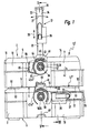
Figur 1- eine sich aus zwei aufeinandergestapelten Behältern
zusammensetzende Behälteranordnung in Seitenansicht
auf eine Seitenfläche, an der der
Traggriff und Drehverriegelungsmittel gelagert
sind, das Ganze in einer Teilschnittdarstellung
gemäß Schnittlinie I-I aus
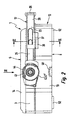
Figur 5, Figur 2- den in
Figur 1 zuoberst abgebildeten Behälter in Einzeldarstellung, wobei der Traggriff aus der inFigur 1 eingenommenen ersten Tragstellung an den Behälterkörper herangeklappt wurde und eine zweite Tragstellung einnimmt, Figur 3- den Behälter aus
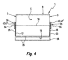
Figur 2 mit in eine andere Position verschwenktem Traggriff, in der es möglich ist, den Behälter durch Anheben seines Deckels zu öffnen, - Figur 4
- eine Draufsicht auf den Behälter aus
Figur 2 mit Blickrichtung gemäß Pfeil IV, Figur 5- eine Teildarstellung der Behälteranordnung aus
Figur 1 im Längsschnitt gemäß Schnittlinie V-V, Figur 6- eine Teildarstellung des Behälters aus
Figur 2 im Schnitt gemäß Schnittlinie VI-VI, und Figur 7- eine der
Figur 6 entsprechende Teildarstellung gemäß Schnittlinie VII-VII ausFigur 1.
- Figure 1
- 4 shows a container arrangement composed of two stacked containers in a side view on a side surface on which the carrying handle and rotary locking means are mounted, the whole in a partial sectional view according to section line II from FIG. 5,
- Figure 2
- the container shown at the top in FIG. 1, the carrying handle being folded out of the first carrying position assumed in FIG. 1 to the container body and occupying a second carrying position,
- Figure 3
- 2 with the carrying handle pivoted into another position, in which it is possible to open the container by lifting its lid,
- Figure 4
- 3 shows a plan view of the container from FIG. 2 with the viewing direction according to arrow IV,
- Figure 5
- 2 shows a partial representation of the container arrangement from FIG. 1 in a longitudinal section according to section line VV,
- Figure 6
- a partial view of the container of Figure 2 in section along section line VI-VI, and
- Figure 7
- 6 a partial representation corresponding to section line VII-VII from FIG. 1.
In der Zeichnung sind mehrere gleichartig aufgebaute Behälter
1 gezeigt, die jeweils einzeln von einer Person durch manuelles
Tragen transportiert werden können, die aber auch die
vorteilhafte Möglichkeit eröffnen, in einer grundsätzlich beliebigen
Anzahl aufeinandergestapelt und anschließend zu einer
zusammenhängenden Behältereinheit verknüpft zu werden,
wie sie exemplarisch in Figuren 1 und 5 gezeigt ist, und der
allgemein die Bezugsziffer 2 zugeordnet wurde.In the drawing there are several containers of the
Es versteht sich, daß eine vertikale Verknüpfung aufeinandergestapelter
Behälter 1 nicht zwingend notwendig ist. So lange
es nur um eine Aufbewahrung geht können die Behälter auch lose
aufeinandergesetzt werden. Ferner besteht die Möglichkeit,
nur eine ausgewählte Anzahl von Behältern eines Behälterstapels
miteinander zu verknüpfen. Im übrigen läßt sich jeder
Behälter 1 unabhängig von den anderen Behältern separat verwenden.It is understood that a vertical link is stacked on top of one another
Zunächst sei anhand der Zeichnung ein vorteilhafter Aufbau
der Behälter 1 beschrieben. Diese können in ihren Höhenabmessungen
variieren, verfügen jedoch zweckmäßigerweise über eine
identische Grundfläche mit übereinstimmendem Umriß.First of all, based on the drawing, an advantageous structure
the
Jeder Behälter verfügt über einen gehäuseartigen Behälterkörper
3, der im Innern einen Aufnahmeraum 4 definiert, der zur
Aufnahme eines oder mehrerer beliebiger Gegenstände geeignet
ist, die aufbewahrt und/oder transportiert werden sollen. Der
Aufnahmeraum 4 kann sich aus mehreren getrennten Teilräumen
zusammensetzen.Each container has a housing-
Der Behälterkörper 3 ist beim Ausführungsbeispiel in einer
kofferähnlichen Flachbauweise ausgeführt und verfügt über einen
im wesentlichen rechteckförmigen Umriß. Seine Grundfläche
wird von den beiden einander entgegengesetzt orientierten
großflächigeren Außenflächen definiert, die normalerweise
nach oben und unten orientiert sind und die Oberseite 5 und
Unterseite 6 des Behälterkörpers 3 definieren. Der Behälter 1
läßt sich mit dieser Ausrichtung transportieren, wobei er
folglich eine Horizontalausrichtung einnimmt, bei der seine
Hauptausdehnungsebene etwa horizontal verläuft.The
Jeder Behälterkörper 3 hat ferner vier Seitenflächen, und
zwar zwei seitliche Seitenflächen 7, 8, eine rückwärtige Seitenfläche
9 und eine vordere Seitenfläche 10. Diese erstrekken
sich bei Horizontalausrichtung des Behälterkörpers 3 in
vertikaler Richtung.Each
Bevorzugt ist der Behälterkörper 3 mehrteilig aufgebaut. Er
enthält beim Ausführungsbeispiel ein kasten- oder schalenförmiges
Unterteil 13, das eine nach oben weisende Öffnung besitzt,
der ein Deckel 14 des Behälterkörpers 3 zugeordnet
ist. Bei geschlossenem Behälter liegt der Deckel 14 auf dem
Unterteil 13 auf, so daß der Aufnahmeraum 4 ringsum von Wänden
des Behälterkörpers 3 begrenzt ist. Andererseits läßt
sich der Deckel 14 vom Unterteil 13 abheben, um über die dann
freiliegende Öffnung des Unterteils 13 dessen Innenraum zugänglich
zu machen und Produkte einzuladen oder herauszunehmen.
Prinzipiell kann der Deckel 14 ein bezüglich dem Unterteil
13 völlig separates Teil sein, das sich zum öffnen des
Behälters 1 komplett abnehmen läßt. Vorzugsweise ist der Dekkel
14 jedoch wie beim Ausführungsbeispiel am Unterteil 13
und insbesondere im rückseitigen Bereich schwenkbar gelagert,
so daß er zum Öffnen und Verschließen des Behälters 1 gemäß
Doppelpfeil 15 hochgeschwenkt bzw. herabgeschwenkt werden
kann. Der die horizontale Schwenkachse definierende Schwenkbereich
ist in der Zeichnung bei 16 angedeutet.The
Jeder Behälter 1 enthält einen den einfachen Tragetransport
ermöglichen Traggriff 17. Dieser ist der Oberseite 5 des Behälterkörpers
3 zugeordnet, befindet sich also beim Tragen
des Behälters 1 üblicherweise im Bereich dessen Oberseite 5.Each
Obgleich der Traggriff 17 als starrer Bestandteil des Behälterkörpers
3 ausgeführt sein könnte, wobei insbesondere in
den Deckel 14 versenkte Bauform infrage käme, empfiehlt sich
die beim Ausführungsbeispiel vorhandene Ausgestaltung als am
Behälterkörper 3 um eine horizontale Drehachse 18 verschwenkbarer
Traggriff. Dabei ist beim Ausführungsbeispiel die Möglichkeit
gegeben, den Traggriff 17 wahlweise in der beim oberen
Behälter 1 der Figur 1 vorliegenden hochgeschwenkten ersten
Tragstellung 22 sowie ersten oder zweiten, an den Behälterkörper
3 herangeklappten Stellungen 23, 24 zu positionieren,
wobei er in der ersten herangeklappten Stellung 23 ausgehend
von der hochragenden ersten Tragstellung 22 nach vorne
und in der zweiten herangeklappten Stellung 24 zur Rückseite
hin umgeklappt ist.Although the
Der Traggriff 17 ist beim Ausführungsbeispiel als im wesentlichen
U-förmig konturierter Bügelgriff gestaltet. Seine
Schwenklagerung erfolgt im Bereich der freien Enden seiner
seitlichen Griffschenkel 25. Die die Griffschenkel verbindende
horizontale Griffpartie bildet einen Handhabungsabschnitt
26, an dem der Traggriff 17 zum Transport des Behälters 1 und
insbesondere auch zum Verschwenken des Traggriffes 17 mit einer
Hand erfaßt werden kann. In der hochgeschwenkten ersten
Tragstellung 22 ist der Handhabungsabschnitt 26 nach oben
orientiert und mit Abstand oberhalb der oberseitigen Fläche
des Behälterkörpers 3 plaziert. In den beiden herangeklappten
Stellungen 23, 24 ist der Handhabungsabschnitt 26 hingegen
seitwärts orientiert, wobei er in der ersten herangeklappten
Stellung 23 der vorderen Seitenfläche 10 und in der zweiten
herangeklappten Stellung 24 der rückwärtigen Seitenfläche 9
des Behälterkörpers 3 zugeordnet ist, jeweils in Draufsicht
von oben auf den Behälterkörper 3 gesehen. Die Schwenkmöglichkeit
ist in Figur 1 durch Doppelpfeil 27 angedeutet.The carrying
Die Behälter 1 zeichnen sich nun unter anderem dadurch aus,
daß der Traggriff 17 und der Behälterkörper 3 derart gestalterisch
aneinander angepaßt sind, daß der Traggriff 17 in der
ersten herangeklappten Stellung 23 eine weitere, zweite Tragstellung
28 einnehmen kann, die in Figur 2 abgebildet ist. In
dieser zweiten Tragstellung 28 ist der Handhabungsabschnitt
26 des Traggriffes 17 von der Vorderseite 10 des Behälterkörpers
3 her mit der Hand ergreifbar, so daß sich der Behälter
nicht nur in der schon erwähnten Horizontalausrichtung, sondern
wahlweise auch in einer Hochkantausrichtung tragen läßt.
Wird nämlich der Traggriff 17 in der zweiten Tragstellung 28
bei horizontal ausgerichtetem Behälter 1 erfaßt und hochgehoben,
stellt sich der Behälterkörper 3 auf, so daß seine
Hauptausdehnungsebene in einer Vertikalebene verläuft und der
Handhabungsabschnitt 26 nun wiederum nach oben orientiert
ist, wobei er allerdings der vorderen Seitenfläche 10 zugeordnet
ist. In der Hochkantausrichtung nimmt der Behälter 1
eine Position ein, die sich ergibt, wenn man den Behälter 1
aus Figur 2 gedanklich um 90° im Gegenuhrzeigersinn verdreht.The
Es ist also möglich, in Abhängigkeit von der Beladung des Behälters
1 diesen wahlweise in horizontaler Ausrichtung oder
in vertikaler, Hochkantausrichtung zu tragen. Im letzteren
Falle läßt sich der Behälter vergleichbar einem Aktenkoffer
handhaben.So it is possible depending on the loading of the
Die Drehachse 18 des Traggriffes 17 ist vorzugsweise, in Horizontalausrichtung
des Behälterkörpers 3 gesehen, im Schwerpunktbereich
des Behälterkörpers 3 plaziert. Dieser Bereich
entspricht vorliegend zumindest in etwa dem breitenmittigen
Bereich des Behälterkörpers 3. Dies hat zur Folge, daß die
Position des Behälterkörpers 3 bei in der ersten Tragstellung
befindlichem Traggriff 17 von sich aus sehr stabil ist.
Gleichwohl können bei Bedarf geeignete Sicherungsmittel, beispielsweise
Rastmittel, vorgesehen sein, die den Traggriff 17
in dieser Position relativ zum Behälterkörper 3 lösbar fixieren.The axis of
Damit sich der Behälter 1 auch bei vertikaler Ausrichtung des
Behälterkörpers 3 stabil tragen läßt, ist der Traggriff 17 in
der zweiten Tragstellung 28 zweckmäßigerweise auf leicht lösbare
Art am Behälter 3 bezüglich diesem unverschwenkbar arretierbar.
Hierzu könnten beispielsweise Rastmittel vorgesehen
sein und/oder federbelastete Arretiermittel, die automatisch
verrasten und die durch kurzen manuellen Eingriff deaktiviert
werden können, um den Traggriff 17 bei Bedarf wieder in die
erste Tragstellung 22 zurückzuschwenken. Beim Ausführungsbeispiel
erfolgt die lösbare Arretierung in Verbindung mit einer
Ausgestaltung des verschwenkbaren Traggriffes 17 als Teleskop-Traggriff.So that the
So ist zweckmäßigerweise vorgesehen, daß der beim Ausführungsbeispiel
längliche leistenähnliche Handhabungsabschnitt
26 teleskopierbar an zwei Basisabschnitten 32 des Traggriffes
17 gelagert ist, über die die Drehlagerung des Traggriffes 17
am Behälterkörper 3 erfolgt. Im speziellen Fall des Ausführungsbeispieles
sind die beiden Griffschenkel 25 in zwei in
ihrer Längsrichtung relativ zueinander gemäß Doppelpfeil 33
verschiebbare Abschnitte unterteilt, wobei der äußere Abschnitt
34 fest mit dem Handhabungsabschnitt 26 verbunden ist
und der näher zum Behälterkörper 3 liegende innere Abschnitt
den Basisabschnitt 32 bildet. Der äußere Abschnitt 34 verfügt
über eine sich längs erstreckende Ausnehmung, in die der Basisabschnitt
32 längsverschieblich eintaucht. Allerdings sei
darauf hingewiesen, daß unter dem Ausdruck "teleskopierbar"
auch jede beliebige andere Art und Weise einer längsverschieblichen
Lagerung verstanden werden soll, beispielsweise
eine Bauform, bei der die fraglichen Abschnitte nebeneinanderliegend
aneinander geführt sind.It is expediently provided that that in the embodiment
elongated strip-
Durch die Teleskopierbarkeit gemäß Doppelpfeil 33 besteht die
Möglichkeit, den Abstand zwischen dem Handhabungsabschnitt 26
des Traggriffes 17 und dem Behälterkörper 3 zu verändern. Bei
ausgezogenem Handhabungsabschnitt 26 (dies ist in Figuren 2
und 3, ferner strichpunktiert in Figur 4 und beim oberen Behälter
der Figur 1 gezeigt) ist besagter Abstand größer als
bei zurückgeschobenen bzw. eingeschobenem Handhabungsabschnitt
26, was in Figur 4 in durchgezogenen Linien sowie in
Figur 1 in Verbindung mit dem unteren Behälter 1 dargestellt
ist.Due to the telescopic ability according to
Es besteht nun die Möglichkeit, den Traggriff 17 in der zweiten
Tragstellung 28 über den teleskopierbaren Handhabungsabschnitt
26 am Behälterkörper 3 unverschwenkbar zu arretieren.There is now the possibility of carrying
In diesem Zusammenhang sind mit dem Handhabungsabschnitt 26
erste Arretiermittel 35 fest verbunden, die beim Ausführungsbeispiel
an den beiden äußeren Abschnitten 34 der Griffschenkel
25 vorgesehen sind und von jeweils einem oder mehreren
Vorsprüngen gebildet sind, die zum Behälterkörper 3 weisen.
Dabei ist zu erwähnen, daß die Abmessungen des Traggriffes 17
vorzugsweise so gewählt sind, daß er sich über die gesamte
Länge des Behälterkörpers 17 erstreckt, wobei sich die Drehlagerstellen
36 im Bereich der seitlichen Seitenflächen 7, 8
des Behälterkörpers 3 befinden, letzterer also vom Traggriff
17 bügelartig übergriffen wird und die Basisabschnitte 32 die
beiden seitlichen Seitenflächen 7, 8 außen flankieren. Ist
der Traggriff 17 in die erste herangeklappte Stellung 23 verschwenkt,
verlaufen mithin die beiden Griffschenkel 25 ebenfalls
neben den seitlichen Seitenflächen 7, 8 in Richtung zur
vorderen Seitenfläche 10. Die ersten Arretiermittel 35 sind
dabei den seitlichen Seitenflächen 7, 8 zugewandt.In this connection, the
An den beiden seitlichen Seitenflächen 7, 8 sind nun zweite
Arretiermittel 37 vorgesehen, die beim Ausführungsbeispiel
vorsprungartig ausgeführt sind und von der betreffenden Seitenfläche
9, 10 wegragen. Die Zuordnung zu den ersten Arretiermitteln
35 ist derart, daß sie bei eingeschobenem Handhabungsabschnitt
26 wirkungslos sind und nicht kooperieren können,
so daß die freie Schwenkbeweglichkeit des Traggriffes 17
gegeben ist. Ist jedoch der Traggriff 17 in die erste herangeklappte
Stellung 23 verschwenkt und wird anschließend der
Handhabungsabschnitt 26 herausgezogen, gelangen die ersten
Arretiermittel 35 in Eingriff mit den zweiten Arretiermitteln
37, die sie an der der Unterseite 6 zugewandten Seite hintergreifen,
so daß der Traggriff 17 an einem erneuten Hochschwenken
in die erste Tragstellung 22 gehindert ist. In diesem
Zusammenhang ist noch zu erwähnen, daß der Traggriff 17
in der ersten herangeklappten Stellung 23 am Behälterkörper 3
anliegt und nicht weiter nach unten verschwenkt werden kann,
so daß die Arretiermittel 35, 37 lediglich ein Zurückschwenken
verhindern müssen.On the two lateral side surfaces 7, 8 there are now second ones
Locking means 37 provided in the embodiment
are designed in a projecting manner and from the side surface in
Die Freigabestellung, in der die Arretiermittel 35, 37 wirkungslos
sind, ist in Figur 1 beim unteren Behälter 1 ersichtlich.
Die Arretierstellung, in der die Arretiermittel
35, 37 wirksam sind, geht aus Figur 2 hervor. Es ist nun
zweckmäßigerweise vorgesehen, daß die zweite Tragstellung 28
des Traggriffes 17 dann vorliegt, wenn der Handhabungsabschnitt
26 bei der ersten herangeklappten Stellung 23 befindlichem
Traggriff 17 herausgezogen ist, so daß die beiderseitigen
Arretiermittel 35, 37 wirksam sind. Der Handhabungsabschnitt
26 befindet sich dann in einem ausreichenden Abstand
zum Behälterkörper 3 in einem dessen vorderer Seitenfläche 10
vorgelagerten Position, um ein bequemes Umgreifen mit einer
Hand zu ermöglichen.The release position in which the locking means 35, 37 ineffective
are shown in Figure 1 in the
Zwar könnte die beiderseitige Anpassung von Traggriff 17 und
Behälterkörper 3 auch so erfolgen, daß der Handhabungsabschnitt
26 in der zweiten Tragstellung 28 in inmittelbarer
Nähe des Behälterkörpers 3 angeordnet ist. Eine solche Position
liegt beispielsweise bei eingeschobenem Handhabungsabschnitt
26 vor oder könnte dadurch fest vorgegeben werden,
daß auf eine Teleskopierbarkeit des Traggriffes 17 verzichtet
wird. Um in diesem Falle ein bequemes Umgreifen des Handhabungsabschnittes
26 zu ermöglichen, wird es jedoch regelmäßig
der Einformung von Vertiefungen am Behälterkörper 3 bedürfen,
was in der Regel das Volumen des Aufnahmeraumes 4 reduzieren
wird. Die teleskopierbare Bauform ist daher vorzuziehen.The mutual adjustment of
Bei Bedarf kann ferner vorgesehen sein, daß der Handhabungsabschnitt
26 in der eingeschobenen Stellung und/oder in der
herausgezogenen Stellung relativ zu den zugeordneten Basisabschnitten
32 unverschiebbar arretierbar ist. Entsprechende
Arretiermittel könnten insbesondere in dem Kooperationsbereich
38 zwischen den äußeren Abschnitten 34 und den Basisabschnitten
32 der Griffschenkel 25 vorgesehen sein. Hier wäre
insbesondere eine Bauform denkbar, bei der die relativ zueinander
verschiebbaren Teile in einer oder in beiden Stellungen
federbelastet verrasten und durch kurzzeitigen manuellen Eingriff
zur Überwindung der Federvorspannung eine Entrastung
vorgenommen werden kann.If necessary, it can also be provided that the
Bei allen Ausführungsformen ist es von Vorteil, wenn die
Schwenklagerung des Traggriffes 17 am Unterteil 17 des Behälterkörpers
3 erfolgt. Dadurch wird insbesondere die vorteilhafte
Möglichkeit gegeben, den Traggriff 17 selbst als Verriegelungsglied
auszuführen, über das die Verriegelung zwischen
Deckel 14 und Unterteil 13 bei geschlossenem Behälter 1
realisiert wird. So ist beim Ausführungsbeispiel vorgesehen,
daß in Abhängigkeit von der momentanen Schwenkposition des
Traggriffes 17 eine Verriegelung zwischen Unterteil 13 und
Deckel 14 stattfindet oder ein entriegelter Zustand vorliegt,
der ein Öffnen des Behälters 1 durch Anheben des Deckels 14
ermöglicht.In all embodiments, it is advantageous if the
Pivot bearing of the
Befindet sich der Traggriff 17 in der ersten Tragstellung 22
oder in der ersten herangeklappten Stellung 23 oder beliebig
zwischen diesen beiden Stellungen, ist die Verriegelung wirksam
und es liegt eine Schließstellung des Traggriffes 17 vor.
Der Deckel 14 kann dann nicht vom Unterteil 13 abgehoben werden.
Um ein Hochschwenken des Deckels zu ermöglichen, ist der
Traggriff 17 in die zweite herangeklappte Stellung 24 zu verlagern,
so daß sein Handhabungsabschnitt 26 in den Bereich
der rückwärtigen Seitenfläche 9 gelangt. Auch diese Stellung
wird wie die erste herangeklappte Stellung 23 durch Anschlagflächen
42 des Behälterkörpers 3 definiert, die ein Weiterschwenken
verhindern.The carrying
Die Verriegelung erfolgt zweckmäßigerweise im Bereich der
Drehlagerstellen 36. In deren Nachbarschaft sind im Bereich
der seitlichen Seitenflächen 7, 8 des Deckels 14 insbesondere
als Vorsprünge ausgeführte erste Verschlußmittel 43 angeordnet,
die, bei Horizontalausrichtung des Behälterkörpers 3 gesehen,
zweckmäßigerweise unmittelbar vertikal oberhalb der
Drehachse 18 plaziert sind. An den beiden Griffschenkeln 25,
zweckmäßigerweise an den gegebenenfalls vorhandenen Basisabschnitten
32, sind zweite Verschlußmittel 44 vorgesehen, die
beim Verschwenken des Traggriffes 17 ebenfalls eine Schwenkbewegung
um die Drehachse 18 ausführen. Sie sind beim Ausführungsbeispiel
von kreisbogenförmigen Wänden gebildet, deren
Krümmungszentrum in der Drehachse 18 liegt und die eine zur
Drehachse 18 hin orientierte kreisbogenförmige zweite Verschlußfläche
46 definieren. An der Oberseite der ersten Verschlußmittel
43 sind erste Verschlußflächen 45 vorgesehen,
die zweckmäßigerweise ebenfalls gekrümmt sind, vorzugsweise
mit der gleichen Krümmung wie die zweiten Verschlußflächen
46. Sie liegen zudem auf der gleichen Kreislinie wie die
zweiten Verschlußflächen 46. The locking is expediently in the area of
Durch entsprechende Anpassung der Bogenlänge der ersten und
zweiten Verschlußmittel 43, 44 wird nun erreicht, daß die ersten
Verschlußmittel 43 von den zweiten Verschlußmitteln 44
an der Oberseite übergriffen werden, solange der Traggriff 17
eine Schließstellung einnimmt. Befindet sich der Traggriff 17
hingegen in seiner zurückgeklappten Offenstellung, sind die
zweiten Verschlußmittel 43 außer Eingriff mit den ersten Verschlußmitteln
43 verschwenkt, so daß ein Hochheben des Dekkels
14 möglich ist.By adjusting the arc length of the first and
second closure means 43, 44 is now achieved that the first
Closure means 43 from the second closure means 44
can be gripped at the top as long as the
Es ist somit gewährleistet, daß der Behälter 1 während seines
Transportes unabhängig von der vorhandenen Tragstellung des
Traggriffes 17 stets zuverlässig verriegelt ist. Ein versehentliches
Öffnen ist ausgeschlossen. Zum Öffnen muß der
Traggriff 17 in die zweite herangeklappte Stellung 24 nach
hinten geklappt werden.It is thus ensured that the
Die Möglichkeit zur Positionierung des Traggriffes 17 in verschiedenen
Tragstellungen ist vor allem auch dann vorteilhaft,
wenn die Behälter 1 die Möglichkeit bieten, eine vertikal
aufeinandergestapelte Behälteranordnung zur realisieren,
die zu einer zusammenhängenden Behältereinheit 2 verknüpft
ist. In diesem Falle sitzen die Behälter 1 gemäß Figur 1 mit
Horizontalausrichtung übereinander, wobei sie durch Kooperation
erster und zweiter Verriegelungsmittel höhenverkettet
sind, so daß beim Hochheben des zuoberst angeordneten Behälters
1 gleichzeitig auch der unter diesem liegende weitere
Behälter mit angehoben wird, desgleichen eventuelle weitere
Behälter, die ebenfalls Bestandteil des verknüpften Behälterstapels
sind. Die Handhabung der Behältereinheit 2 erfolgt in
diesem Falle unter Verwendung des in die erste Tragstellung
22 hochgeschwenkten Traggriffes 17 des obersten Behälters 1,
der in Figur 1 ergänzend mit der Bezugsziffer 1' versehen
ist. Bei allen unter diesem obersten Behälter 1' angeordneten
weiteren Behältern 1 ist der Traggriff 17 zweckmäßigerweise
in die erste herangeklappte Stellung 23 verbracht, insbesondere
mit eingeschobenen Handhabungsabschnitt 26. The possibility of positioning the
Die Verknüpfung der Behälter 1 innerhalb der Behältereinheit
2 erfolgt jeweils paarweise derart, daß ein oberer Behälter
1, 1' mit dem unmittelbar unter diesem plazierten unteren Behälter
1, 1" verknüpft wird. Dadurch ergibt sich eine Verkettung,
die beliebig gelöst und wiederhergestellt werden kann,
um die Anzahl der verknüpften Behälter 1 nach Bedarf zu variieren.Linking
Die schon erwähnten ersten und zweiten Verriegelungsmittel
47, 48 befinden sich ausschließlich im Bereich zweier einander
entgegengesetzter Seitenflächen des Behälterkörpers 3,
wobei sie vorzugsweise den beiden seitlichen Seitenflächen 7,
8 zugeordnet sind. Dabei sind die Verriegelungsmittel 47, 48,
bei Horizontalausrichtung des Behälterkörpers 3 gesehen, im
Schwerpunktbereich des jeweiligen Behälterkörpers 3 plaziert,
so daß eine geradlinige vertikale Kraftübertragung zwischen
den verknüpften Behältern stattfindet und mithin während des
Transportes keine oder zumindest keine relevanten Biegemomente
auftreten, die zu einer Beschädigung der Verriegelungsmechanismen
führen könnten. Die Verriegelungsmaßnahmen sind also
auf den zentralen Bereich eines jeweiligen Behälterkörpers
3 konzentriert, was dem Benutzer eine übersichtliche Handhabung
gestattet, da er lediglich an zwei einander entgegengesetzten
Seitenflächen 7, 8 Manipulationen vorzunehmen hat, um
zwei Behälter 1 zu verknüpfen oder voneinander zu lösen.The first and second locking means already mentioned
47, 48 are located exclusively in the area of two to one another
opposite side surfaces of the
Damit unmittelbar aufeinandersitzende Behälter 1 nicht horizontal
verrutschen können, sind zweckmäßigerweise geeignete
Sicherungsmittel 52, 53 vorhanden, insbesondere in Gestalt
aufeinander abgestimmter Vorsprünge und Vertiefungen, die
sich zweckmäßigerweise an der Unterseite des Unterteils 13
und an der Oberseite des Deckels 14 befinden und die formschlüssig
ineinandereingreifen können.So that
Sollen grundsätzlich nur zwei Behälter in stets der gleichen
Stapelreihenfolge miteinander verknüpft werden, würde es genügen,
am einen Behälter 1 nur die ersten Verriegelungsmittel
47 und am anderen Behälter 1 nur die zweiten Verriegelungsmittel
48 vorzusehen. Beim Ausführungsbeispiel sind jedoch
alle zu verknüpfenden Behälter 1 in identischer Weise mit sowohl
ersten als auch zweiten Verriegelungsmitteln 47, 48 ausgestattet,
so daß eine beliebige Anzahl von Behältern in variabler
Stapelreihenfolge miteinander verknüpft werden kann.
Hierzu sind die ersten und zweiten Verriegelungsmittel 47, 48
eines jeweiligen Behälters an den beiden seitlichen Seitenflächen
7, 8 auf unterschiedlichem Höhenniveau übereinanderliegend
angeordnet, wobei die ersten Verriegelungsmittel 47
oberhalb der zweiten Verriegelungsmittel 48 plaziert sind.
Es ist insbesondere vorgesehen, daß sich die ersten Verriegelungsmittel
47 im Bereich der Oberseite 5 und die zweiten
Verriegelungsmittel 48 im Bereich der Unterseite 6 einer jeweiligen
Seitenfläche 7, 8 befinden. Alle Verriegelungsmittel
47, 48 sind zweckmäßigerweise am Unterteil 13 der Behältereinheit
2 vorgesehen, so daß der im verknüpften Zustand
zwischen zwei Unterteilen 13 liegende Deckel 14 des jeweils
unteren Behälters 1, 1" keine Verknüpfungskräfte übertragen
muß und mithin dessen Schwenkscharniere nicht beansprucht
werden.Basically, only two containers should always be in the same one
Stacking order, it would suffice
on a
Die den beiden Seitenflächen 7, 8 zugeordneten ersten Verriegelungsmittel
47 eines jeweiligen Behälters 1 sind beim Ausführungsbeispiel
als Drehverriegelungsmittel 47' ausgeführt,
deren Drehachsen 54, 55 koaxial zueinander angeordnet sind
und rechtwinkelig zur jeweils zugeordneten Seitenfläche 7, 8
verlaufen. Bei ihrer Drehbetätigung beschränkt sich daher die
Verlagerung der Drehverriegelungsmittel 47' auf eine vertikal
ausgerichtete Ebene, die zur benachbarten Seitenfläche 7, 8
insbesondere parallel verläuft. Es wird also insbesondere
verhindert, daß die Betätigung der ersten Verriegelungsmittel
47 mit einer Vergrößerung der Umrißabmessungen des betreffenden
Behälters 1 verbunden ist, so daß auch unter beengten
Platzverhältnissen eine bequeme Betätigung möglich ist. Es
wäre zwar prinzipiell möglich, anstelle der ersten Verriegelungsmittel
47 die zweiten Verriegelungsmittel 48 als Drehverriegelungsmittel
auszuführen. Die beschriebene Bauform hat
jedoch den Vorteil einer verbesserten Handhabung von oben her
und schafft überdies die beim Ausführungsbeispiel realisierte
vorteilhafte Möglichkeit, die Drehachsen 54, 55 der Drehverriegelungsmittel
47' mit der Drehachse 18 des Traggriffes 17
zusammenfallen zu lassen. Der erforderliche Drehlagerungsaufwand
wird dadurch erheblich reduziert und konzentriert sich
überdies auf einen sehr eingegrenzten Bereich des Behälters
1, was kompakte Abmessungen zuläßt.The first locking means assigned to the two
In diesem Zusammenhang ist beim Ausführungsbeispiel überdies
vorgesehen, daß die Drehlagerung des Traggriffes 17 und die
Drehlagerung der Drehverriegelungsmittel 47' im Bereich der
beiden einander entgegengesetzten seitlichen Seitenflächen 7,
8 des Behälterkörpers 3 über jeweils ein und dasselbe Lagerteil
56 des Behälterkörpers 3 erfolgt.In this context, the embodiment is also
provided that the pivot bearing of the
Im konkreten Fall des Ausführungsbeispiels ist ein jeweiliges
Lagerteil 56 hohlzylindrisch bzw. hülsenähnlich ausgebildet,
man könnte auch von einer rohrstutzenartigen Bauform sprechen,
wobei es ausgehend von der zugeordneten Seitenfläche 7,
8 nach außen ragt. Der Traggriff 17 ist nun über eine am jeweiligen
Griffschenkel 25 vorgesehene, das Lagerteil 56 koaxial
umschließende Lagerhülse 57 am Außenumfang des Lagerteils
56 drehgelagert. Die zugeordneten Drehverbindungsmittel
47' greifen in das betreffende Lagerteil 56 ein und sind in
dessen Innern und/oder am Traggriff 17 drehgelagert. Aufgrund
der dadurch erzielbaren axialen Verschachtelung bzw. Überlappung
der Drehlagerbereiche lassen sich sehr kompakte Abmessungen
erzielen.In the specific case of the exemplary embodiment, there is a respective
Die mit den Drehverriegelungsmitteln 47' kooperierenden zweiten
Verriegelungsmittel 48 sind zweckmäßigerweise als starre
Elemente ausgebildet, die vorzugsweise einstückig mit dem Behälterkörper
3 ausgeführt sind und im verknüpften Zustand
zweier Behälter von den Drehverriegelungsmitteln 47' des jeweils
anderen Behälters hintergriffen werden. Ihr Aufbau kann
zumindest im wesentlichen demjenigen der ersten Verschlußmittel
43 entsprechen.The second cooperating with the rotary locking means 47 '
Locking means 48 are expediently as rigid
Elements formed, preferably in one piece with the
Die am Traggriff 17 vorgesehenen zweiten Verschlußmittel 44
erstrecken sich mit radialem Abstand außerhalb der Lagerhülse
57 und sind am zugeordneten Griffschenkel 25 festgelegt. Die
Verbindung zur Lagerhülse 53 erfolgt beispielsgemäß über einen
ringscheibenförmigen Verbindungsabschnitt 58, der in Figur
5 ersichtlich ist.The second locking means 44 provided on the carrying
Die Drehverriegelungsmittel 47', die beim Ausführungsbeispiel
in Gestalt hakenähnlicher Drehriegel ausgeführt sind, verfügen
über eine scheibenförmige Abschlußwand 59, an die eine
Lagerachse 62 angeformt ist, die zur Drehlagerung und/oder
axialen Fixierung in das Lagerteil 56 eingreift. Die Einstecktiefe
wird durch die Abschlußwand 59 begrenzt, die am
freien Ende des Lagerteils 56 zur Anlage gelangt und zugleich
die Lagerhülse 57, den Verbindungsabschnitt 58 und die zweiten
Verschlußmittel 44 des Traggriffes 17 überdeckt. Indem
die Drehverriegelungsmittel 47' axial unverschieblich am Behälterkörper
3 fixiert sind, übernehmen sie gleichzeitig die
entsprechende Fixierung der Drehverriegelungsmittel 47' bezüglich
dem Behälterkörper 3.The rotary locking means 47 ', which in the embodiment
are designed in the form of hook-like rotary bolts
via a disk-shaped
Die Drehverriegelungsmittel 47' sind vorzugsweise verrastend
am Behälterkörper 3 fixiert, wobei das Ausführungsbeispiel
einen Rasteingriff zwischen der Lagerachse 62 und dem Behälterkörper
3 vorsieht. Die Lagerachse 62 kann hierzu über radial
federelastische Rastarme verfügen.The rotary locking means 47 'are preferably latching
fixed to the
Die Drehverriegelungsmittel 47' können zum Erhalt einer sicheren
Führung über zusätzliche Drehführungsmittel 63 verfügen.
Diese enthalten beim Ausführungsbeispiel eine kreisbogenförmig
geformte Wand, deren radial nach innen weisende Innenfläche
an der zugewandten gekrümmten Außenfläche der zweiten
Verschlußmittel 44 anliegt, wobei die Krümmungsradien
übereinstimmen, so daß die vorerwähnten Komponenten bei der
Drehbewegung aneinander abgleiten können. Die Drehverriegelungsmittel
47' können also über den Traggriff 17 bzw. dessen
zweiten Verschlußmitteln 44 am Behälterkörper 3 drehgelagert
sein.The rotary locking means 47 'can be used to obtain a secure
Guide have additional rotary guide means 63.
In the exemplary embodiment, these contain a circular arc
shaped wall, the radially inward facing inner surface
on the facing curved outer surface of the second
Closure means 44 abuts, the radii of curvature
match, so that the aforementioned components in the
Can slide rotational movement against each other. The rotary locking means
47 'can thus via the
Radial weiter außen verfügen die Drehverriegelungsmittel 47'
desweiteren über einen beispielsgemäß hakenähnlich konzipierten
Verriegelungsabschnitt 64. Er hat eine nach radial innen
weisende erste Verriegelungsfläche 65, deren Abstand zur zugeordneten
Drehachse 54, 55 gleich groß ist wie der bei aufeinandersitzenden
Behältern gemessene Abstand zwischen der
vorerwähnten Drehachse 54, 55 und einer von dieser Drehachse
54, 55 wegweisenden und insbesondere nach oben hin orientierten
zweiten Verriegelungsfläche 66 des am darüber angeordneten
Behälterkörper 3 vorgesehenen zweiten Verriegelungsmittels
48.Radially further out, the rotary locking means 47 '
furthermore via a hook-like designed according to the
Die Figur 1 zeigt beim oberen Behälter 1 die Drehverriegelungsmittel
47' in deaktivierter Stellung. Sie sind derart
drehpositioniert, daß sich der Verriegelungsabschnitt 64
seitlich neben der zugeordneten Drehlagerstelle 36 befindet
und insbesondere nicht über die Oberseite 5 des Behälterkörpers
3 hinausragt. In dieser Position kann ein weiterer Behälter
1 aufgesetzt werden. Um die Verriegelung anschließend
zu aktivieren, werden die Drehverriegelungsmittel 47' soweit
verdreht, bis ihre Verriegelungsabschnitte 64 das zweite Verriegelungsmittel
48 des oberen Behälters 1 übergreifen. Dieser
Zustand liegt zwischen den beiden in Figur 1 dargestellten
Behältern 1 vor. Damit hier eine problemlose Betätigung
möglich ist, empfiehlt es sich, die beiden Verriegelungsflächen
65, 66 ebenfalls kreisbogenförmig zu konturieren, wobei
der Krümmungsmittelpunkt auf der Drehachse 54, 55 liegt. Bei
Bedarf kann durch Rastmittel oder andere Sicherungsmittel eine
lösbare Fixierung der Verriegelungsmittel erfolgen.FIG. 1 shows the rotary locking means for the
Vorteilhafterweise lassen sich die Drehverriegelungsmittel
47' unabhängig vom Traggriff 17 verschwenken, solange dieser
eine der beiden Tragstellungen oder die erste heruntergeklappte
Stellung 23 einnimmt.The rotary locking means can advantageously be
47 'pivot independently of the
Claims (18)
- Container assembly with at least two stackable containers (1), each having a container body (3) defining a holding space (4) for one or more objects and which is equipped in the area of opposite side faces (7, 8) with locking means (47, 48) in such a way that two container bodies (3) resting directly on top of one another may be connected releasably to form a unit (2) through the cooperation of first locking means (47) provided on the lower container body with second locking means (48) provided on the container body (3) resting on top, wherein at least the top (5) of the upper container body (3) is assigned a carrying handle (17), characterised in that the first and second locking means (47, 48) are placed on two opposite side faces (7, 8) in the area of the centre of gravity of the respective container body (3), wherein the first or second locking means (47, 48) are in the form of rotary locking means (47') with rotation axes (54, 55) coaxial to one another.
- Container assembly according to claim 1, characterised in that two containers (1) capable of resting directly on top of one another have on their container bodies (3) both first and second locking means (47, 48).
- Container assembly according to claim. 2, characterised in that the first and second locking means (47, 48) of each container (1) are arranged above one another at different heights, with the first locking means (47) being placed above the second locking means (48).
- Container assembly according to any of claims 1 to 3, characterised in that the locking means which cooperate with the rotary locking means (47') are in particular rigid elements integral with the container body (3) and which in the locked state are engaged by the rotary locking means (47') from behind.
- Container assembly according to any of claims 1 to 4, characterised in that the first locking means (47) are designed as rotary locking means (47').
- Container assembly according to any of claims 1 to 5, characterised in that the top (5) of the container body (3) of the container (1) equipped with rotary locking means (47') is assigned a swivelling pivotably mounted carrying handle (17) in the area of the centre of gravity of the container body (3).
- Container assembly according to claim 6, characterised in that the rotary axis (18) of the carrying handle (17) and the rotation axes (54, 55) of the rotary locking means (47') of each container (1) coincide.
- Container assembly according to claim 7, characterised in that the pivot mounting of the carrying handle (17) and the pivot mounting of the rotary locking means (47') are effected in the area of the two opposing side faces (7, 8) of the container body (3) via one and the same bearing part (56) of the container body (3).
- Container assembly according to claim 8, characterised in that each of the two bearing parts (56) is sleeve-like in form, with the carrying handle (17) mounted on the outside and the assigned rotary locking means (47') engaging inside the bearing part (56) concerned.
- Container assembly according to any of claims 7 to 9, characterised in that the carrying handle (17) is fixed to the container body (3) by the rotary locking means (47').
- Container assembly according to any of claims 1 to 10, characterised in that the rotary locking means (47') are locked to the container body (3).
- Container assembly according to any of claims 1 to 11, characterised in that the container body (3) of at least one container (1) and preferably of several containers (1) has a box- or bowl-shaped bottom part (13) and a cover (14) assigned to the upwards-facing opening of the bottom part (13), wherein the locking means (47, 48) are fitted to the bottom part (13).
- Container assembly according to claim 12, characterised in that the carrying handle (17) is pivotably mounted on the bottom part (13) of the container body (3) and is capable of swivelling.
- Container assembly according to claim 13, characterised in that the carrying handle (17) is in the form of a locking element and, depending on its swivel position, effects locking between bottom part (13) and cover (14) with the container closed, or allows opening of the container (1).
- Container assembly according to any of claims 1 to 14, characterised in that one or more containers (1) have a case-like flat design, with the carrying handle (17) assigned to their larger-surface top (5), wherein the carrying handle (17) may be swivelled between a swivelled-up carrying position in which its handling section (26) is oriented upwards, and a position folded on to the container body (3) in which its handling section (26) is oriented sideways, and wherein the carrying handle (17) and the container body (3) are so matched to one another that in the folded-on position the carrying handle (17) can adopt a further carrying position, in which its handling section (26) can be grasped from the side of the container body (3), to allow optional carrying of the individual container (1) aligned in its end.
- Container assembly according to claim 15, characterised in that, in the folded-on position, the carrying handle (17) is releasably locked to the container body (3) so as to be incapable of swivelling.
- Container assembly according to any of claims 15 or 16, characterised in that the handling section (26) is mounted so as to be capable of retracting on at least one swivelling base section (32) of the carrying handle (17) pivotably mounted on the container body (3), in such a way that the distance between the handling section (26) and the container body (3) may be varied.
- Container assembly according to claim 17 in conjunction with claim 16, characterised in that the locking of the carrying handle (17) to the container body (3) is effected via the retractable handling section (26).
Priority Applications (4)
| Application Number | Priority Date | Filing Date | Title |
|---|---|---|---|
| ES99109382T ES2189311T3 (en) | 1999-06-02 | 1999-06-02 | DISPOSITION OF CONTAINERS. |
| AT99109382T ATE232487T1 (en) | 1999-06-02 | 1999-06-02 | CONTAINER ARRANGEMENT |
| EP99109382A EP1059240B1 (en) | 1999-06-02 | 1999-06-02 | Container Arrangement |
| DE59904274T DE59904274D1 (en) | 1999-06-02 | 1999-06-02 | A container assembly |
Applications Claiming Priority (1)
| Application Number | Priority Date | Filing Date | Title |
|---|---|---|---|
| EP99109382A EP1059240B1 (en) | 1999-06-02 | 1999-06-02 | Container Arrangement |
Publications (2)
| Publication Number | Publication Date |
|---|---|
| EP1059240A1 EP1059240A1 (en) | 2000-12-13 |
| EP1059240B1 true EP1059240B1 (en) | 2003-02-12 |
Family
ID=8238158
Family Applications (1)
| Application Number | Title | Priority Date | Filing Date |
|---|---|---|---|
| EP99109382A Expired - Lifetime EP1059240B1 (en) | 1999-06-02 | 1999-06-02 | Container Arrangement |
Country Status (4)
| Country | Link |
|---|---|
| EP (1) | EP1059240B1 (en) |
| AT (1) | ATE232487T1 (en) |
| DE (1) | DE59904274D1 (en) |
| ES (1) | ES2189311T3 (en) |
Cited By (6)
| Publication number | Priority date | Publication date | Assignee | Title |
|---|---|---|---|---|
| WO2011000387A1 (en) | 2009-06-29 | 2011-01-06 | Tts Tooltechnic Systems Ag & Co. Kg | Stackable container assembly with reciprocal locking of the stacked containers |
| WO2011000385A1 (en) | 2009-06-29 | 2011-01-06 | Tts Tooltechnic Systems Ag & Co. Kg | Stackable container assembly with reciprocal locking of the stacked containers |
| DE202009018589U1 (en) | 2009-06-29 | 2012-03-08 | Tts Tooltechnic Systems Ag & Co. Kg | A container assembly |
| DE202009018588U1 (en) | 2009-06-29 | 2012-03-08 | Tts Tooltechnic Systems Ag & Co. Kg | A container assembly |
| DE102016112853A1 (en) * | 2016-07-13 | 2018-01-18 | Bs Systems Gmbh & Co. Kg | Stackable system tray |
| KR101955087B1 (en) | 2017-03-31 | 2019-03-06 | 이재전 | Nursing bottle sterilizer |
Families Citing this family (7)
| Publication number | Priority date | Publication date | Assignee | Title |
|---|---|---|---|---|
| AT9332U1 (en) * | 2006-07-12 | 2007-08-15 | Weikinger Peter | CONTAINER |
| ES2613637T3 (en) | 2009-06-29 | 2017-05-25 | Tts Tooltechnic Systems Ag & Co. Kg | Portable container |
| US8677661B2 (en) | 2009-09-15 | 2014-03-25 | Tts Tooltechnic Systems Ag & Co. Kg | Container arrangement |
| CN102783795A (en) * | 2012-07-05 | 2012-11-21 | 苏州群泰包装制品有限公司 | Precision watch box with dual safety lock structure |
| US9393684B2 (en) | 2014-04-01 | 2016-07-19 | Meridian International Co., Ltd. | Toolbox |
| CA2989919C (en) * | 2015-07-24 | 2022-12-06 | Tts Tooltechnic Systems Ag & Co. Kg | Storage equipment |
| CN108813872A (en) * | 2018-07-09 | 2018-11-16 | 浙江御匠箱包有限公司 | A kind of stackable luggage case |
Family Cites Families (4)
| Publication number | Priority date | Publication date | Assignee | Title |
|---|---|---|---|---|
| US4109789A (en) * | 1977-09-28 | 1978-08-29 | Plastic Reel Corporation Of America | Self-contained latch constructions for interlocking containers in stacked relation |
| US4351448A (en) * | 1980-08-08 | 1982-09-28 | General Electric Company | Packaging container for mining and construction tools |
| NL8901236A (en) * | 1989-05-18 | 1990-12-17 | Stamicarbon | HOLDER FITTED WITH A LOCKABLE LID. |
| DE4201264A1 (en) * | 1992-01-18 | 1993-07-22 | Festo Kg | STACKABLE CASE |
-
1999
- 1999-06-02 ES ES99109382T patent/ES2189311T3/en not_active Expired - Lifetime
- 1999-06-02 EP EP99109382A patent/EP1059240B1/en not_active Expired - Lifetime
- 1999-06-02 AT AT99109382T patent/ATE232487T1/en not_active IP Right Cessation
- 1999-06-02 DE DE59904274T patent/DE59904274D1/en not_active Expired - Lifetime
Cited By (6)
| Publication number | Priority date | Publication date | Assignee | Title |
|---|---|---|---|---|
| WO2011000387A1 (en) | 2009-06-29 | 2011-01-06 | Tts Tooltechnic Systems Ag & Co. Kg | Stackable container assembly with reciprocal locking of the stacked containers |
| WO2011000385A1 (en) | 2009-06-29 | 2011-01-06 | Tts Tooltechnic Systems Ag & Co. Kg | Stackable container assembly with reciprocal locking of the stacked containers |
| DE202009018589U1 (en) | 2009-06-29 | 2012-03-08 | Tts Tooltechnic Systems Ag & Co. Kg | A container assembly |
| DE202009018588U1 (en) | 2009-06-29 | 2012-03-08 | Tts Tooltechnic Systems Ag & Co. Kg | A container assembly |
| DE102016112853A1 (en) * | 2016-07-13 | 2018-01-18 | Bs Systems Gmbh & Co. Kg | Stackable system tray |
| KR101955087B1 (en) | 2017-03-31 | 2019-03-06 | 이재전 | Nursing bottle sterilizer |
Also Published As
| Publication number | Publication date |
|---|---|
| ES2189311T3 (en) | 2003-07-01 |
| DE59904274D1 (en) | 2003-03-20 |
| ATE232487T1 (en) | 2003-02-15 |
| EP1059240A1 (en) | 2000-12-13 |
Similar Documents
| Publication | Publication Date | Title |
|---|---|---|
| EP1059239B1 (en) | Portable container | |
| EP2994274B1 (en) | Container assembly | |
| EP2313321B1 (en) | Stackable container assembly with reciprocal locking of the stacked containers | |
| EP3294501B1 (en) | Storage equipment | |
| EP2315701B1 (en) | Stackable container assembly with reciprocal locking of the stacked containers | |
| EP1305145B1 (en) | Tool box | |
| EP3484664B1 (en) | Stackable system container | |
| EP1059240B1 (en) | Container Arrangement | |
| DE2403116A1 (en) | HAND SUITCASE WITH WHEELS ARRANGED ON THE UNDER SIDE AND WITH A TOWEL-LIKE HANDLE | |
| EP1060999B1 (en) | Container, in particular for transporting fruits and vegetables | |
| EP0555533A1 (en) | Stackable container | |
| EP3814065B1 (en) | Storage device | |
| EP3817895B1 (en) | Storage device | |
| EP1884438A2 (en) | Wheeled container for piece goods | |
| EP1018473B1 (en) | Container assembly | |
| DE202009018589U1 (en) | A container assembly | |
| EP1894849B1 (en) | Transport and storage container with adjustable side walls | |
| EP3158907B1 (en) | Foldable and pivotable support handle, in particular for the sanitary field | |
| EP4059860A1 (en) | Stackable container with foldable walls | |
| EP3363748B1 (en) | Stackable and nestable container | |
| EP0573064B1 (en) | Accumulator with a fold-away handle | |
| EP0376159B1 (en) | Handling appliance for storing-boxes | |
| DE102016120750A1 (en) | ROLLER TANK WITH DUAL ALIGNMENT | |
| DE202009018588U1 (en) | A container assembly | |
| EP0563420B1 (en) | Collapsible storage and transport crate |
Legal Events
| Date | Code | Title | Description |
|---|---|---|---|
| PUAI | Public reference made under article 153(3) epc to a published international application that has entered the european phase |
Free format text: ORIGINAL CODE: 0009012 |
|
| 17P | Request for examination filed |
Effective date: 19991222 |
|
| AK | Designated contracting states |
Kind code of ref document: A1 Designated state(s): AT BE CH DE DK ES FI FR GB IT LI NL SE |
|
| AX | Request for extension of the european patent |
Free format text: AL;LT;LV;MK;RO;SI |
|
| AKX | Designation fees paid |
Free format text: AT BE CH DE DK ES FI FR GB IT LI NL SE |
|
| GRAG | Despatch of communication of intention to grant |
Free format text: ORIGINAL CODE: EPIDOS AGRA |
|
| 17Q | First examination report despatched |
Effective date: 20020214 |
|
| RAP1 | Party data changed (applicant data changed or rights of an application transferred) |
Owner name: TTS TOOLTECHNIC SYSTEMS AG & CO. KG |
|
| GRAG | Despatch of communication of intention to grant |
Free format text: ORIGINAL CODE: EPIDOS AGRA |
|
| GRAH | Despatch of communication of intention to grant a patent |
Free format text: ORIGINAL CODE: EPIDOS IGRA |
|
| GRAH | Despatch of communication of intention to grant a patent |
Free format text: ORIGINAL CODE: EPIDOS IGRA |
|
| GRAH | Despatch of communication of intention to grant a patent |
Free format text: ORIGINAL CODE: EPIDOS IGRA |
|
| GRAA | (expected) grant |
Free format text: ORIGINAL CODE: 0009210 |
|
| AK | Designated contracting states |
Designated state(s): AT BE CH DE DK ES FI FR GB IT LI NL SE |
|
| PG25 | Lapsed in a contracting state [announced via postgrant information from national office to epo] |
Ref country code: GB Free format text: LAPSE BECAUSE OF FAILURE TO SUBMIT A TRANSLATION OF THE DESCRIPTION OR TO PAY THE FEE WITHIN THE PRESCRIBED TIME-LIMIT Effective date: 20030212 Ref country code: FI Free format text: LAPSE BECAUSE OF FAILURE TO SUBMIT A TRANSLATION OF THE DESCRIPTION OR TO PAY THE FEE WITHIN THE PRESCRIBED TIME-LIMIT Effective date: 20030212 |
|
| REG | Reference to a national code |
Ref country code: GB Ref legal event code: FG4D Free format text: NOT ENGLISH |
|
| REG | Reference to a national code |
Ref country code: CH Ref legal event code: EP |
|
| REF | Corresponds to: |
Ref document number: 59904274 Country of ref document: DE Date of ref document: 20030320 Kind code of ref document: P |
|
| PG25 | Lapsed in a contracting state [announced via postgrant information from national office to epo] |
Ref country code: SE Free format text: LAPSE BECAUSE OF FAILURE TO SUBMIT A TRANSLATION OF THE DESCRIPTION OR TO PAY THE FEE WITHIN THE PRESCRIBED TIME-LIMIT Effective date: 20030512 Ref country code: DK Free format text: LAPSE BECAUSE OF FAILURE TO SUBMIT A TRANSLATION OF THE DESCRIPTION OR TO PAY THE FEE WITHIN THE PRESCRIBED TIME-LIMIT Effective date: 20030512 |
|
| PG25 | Lapsed in a contracting state [announced via postgrant information from national office to epo] |
Ref country code: AT Free format text: LAPSE BECAUSE OF NON-PAYMENT OF DUE FEES Effective date: 20030602 |
|
| PG25 | Lapsed in a contracting state [announced via postgrant information from national office to epo] |
Ref country code: LI Free format text: LAPSE BECAUSE OF NON-PAYMENT OF DUE FEES Effective date: 20030630 Ref country code: CH Free format text: LAPSE BECAUSE OF NON-PAYMENT OF DUE FEES Effective date: 20030630 Ref country code: BE Free format text: LAPSE BECAUSE OF NON-PAYMENT OF DUE FEES Effective date: 20030630 |
|
| REG | Reference to a national code |
Ref country code: ES Ref legal event code: FG2A Ref document number: 2189311 Country of ref document: ES Kind code of ref document: T3 |
|
| GBV | Gb: ep patent (uk) treated as always having been void in accordance with gb section 77(7)/1977 [no translation filed] |
Effective date: 20030212 |
|
| ET | Fr: translation filed | ||
| PLBE | No opposition filed within time limit |
Free format text: ORIGINAL CODE: 0009261 |
|
| STAA | Information on the status of an ep patent application or granted ep patent |
Free format text: STATUS: NO OPPOSITION FILED WITHIN TIME LIMIT |
|
| BERE | Be: lapsed |
Owner name: TOOLTECHNIC SYSTEMS A.G. & CO. K.G. *TTS Effective date: 20030630 |
|
| 26N | No opposition filed |
Effective date: 20031113 |
|
| REG | Reference to a national code |
Ref country code: CH Ref legal event code: PL |
|
| PGFP | Annual fee paid to national office [announced via postgrant information from national office to epo] |
Ref country code: NL Payment date: 20120620 Year of fee payment: 14 |
|
| PGFP | Annual fee paid to national office [announced via postgrant information from national office to epo] |
Ref country code: FR Payment date: 20120705 Year of fee payment: 14 |
|
| PGFP | Annual fee paid to national office [announced via postgrant information from national office to epo] |
Ref country code: IT Payment date: 20120619 Year of fee payment: 14 |
|
| PGFP | Annual fee paid to national office [announced via postgrant information from national office to epo] |
Ref country code: ES Payment date: 20120521 Year of fee payment: 14 |
|
| REG | Reference to a national code |
Ref country code: NL Ref legal event code: V1 Effective date: 20140101 |
|
| REG | Reference to a national code |
Ref country code: FR Ref legal event code: ST Effective date: 20140228 |
|
| PG25 | Lapsed in a contracting state [announced via postgrant information from national office to epo] |
Ref country code: NL Free format text: LAPSE BECAUSE OF NON-PAYMENT OF DUE FEES Effective date: 20140101 |
|
| PG25 | Lapsed in a contracting state [announced via postgrant information from national office to epo] |
Ref country code: IT Free format text: LAPSE BECAUSE OF NON-PAYMENT OF DUE FEES Effective date: 20130602 Ref country code: FR Free format text: LAPSE BECAUSE OF NON-PAYMENT OF DUE FEES Effective date: 20130701 |
|
| REG | Reference to a national code |
Ref country code: ES Ref legal event code: FD2A Effective date: 20150710 |
|
| PG25 | Lapsed in a contracting state [announced via postgrant information from national office to epo] |
Ref country code: ES Free format text: LAPSE BECAUSE OF NON-PAYMENT OF DUE FEES Effective date: 20130603 |
|
| PGFP | Annual fee paid to national office [announced via postgrant information from national office to epo] |
Ref country code: DE Payment date: 20150429 Year of fee payment: 17 |
|
| REG | Reference to a national code |
Ref country code: DE Ref legal event code: R119 Ref document number: 59904274 Country of ref document: DE |
|
| PG25 | Lapsed in a contracting state [announced via postgrant information from national office to epo] |
Ref country code: DE Free format text: LAPSE BECAUSE OF NON-PAYMENT OF DUE FEES Effective date: 20170103 |