EP3814065B1 - Storage device - Google Patents
Storage device Download PDFInfo
- Publication number
- EP3814065B1 EP3814065B1 EP18769702.4A EP18769702A EP3814065B1 EP 3814065 B1 EP3814065 B1 EP 3814065B1 EP 18769702 A EP18769702 A EP 18769702A EP 3814065 B1 EP3814065 B1 EP 3814065B1
- Authority
- EP
- European Patent Office
- Prior art keywords
- handle
- arresting
- housing
- container
- front handle
- Prior art date
- Legal status (The legal status is an assumption and is not a legal conclusion. Google has not performed a legal analysis and makes no representation as to the accuracy of the status listed.)
- Active
Links
- 230000008878 coupling Effects 0.000 claims description 19
- 238000010168 coupling process Methods 0.000 claims description 19
- 238000005859 coupling reaction Methods 0.000 claims description 19
- 230000000694 effects Effects 0.000 claims description 9
- 238000013459 approach Methods 0.000 claims description 3
- 230000003993 interaction Effects 0.000 claims description 2
- 230000002093 peripheral effect Effects 0.000 description 12
- 238000000034 method Methods 0.000 description 7
- 230000008569 process Effects 0.000 description 7
- 238000005452 bending Methods 0.000 description 5
- 230000008901 benefit Effects 0.000 description 4
- 238000013461 design Methods 0.000 description 4
- 230000004069 differentiation Effects 0.000 description 4
- 238000003780 insertion Methods 0.000 description 3
- 230000037431 insertion Effects 0.000 description 3
- 238000004519 manufacturing process Methods 0.000 description 3
- 239000000463 material Substances 0.000 description 3
- 230000005489 elastic deformation Effects 0.000 description 2
- 230000008859 change Effects 0.000 description 1
- 230000000295 complement effect Effects 0.000 description 1
- 238000010276 construction Methods 0.000 description 1
- 230000009849 deactivation Effects 0.000 description 1
- 238000011161 development Methods 0.000 description 1
- 230000018109 developmental process Effects 0.000 description 1
- 230000002349 favourable effect Effects 0.000 description 1
- 238000009432 framing Methods 0.000 description 1
- 238000007654 immersion Methods 0.000 description 1
- 230000008439 repair process Effects 0.000 description 1
- 230000000284 resting effect Effects 0.000 description 1
- 230000008093 supporting effect Effects 0.000 description 1
Images


Classifications
-
- B—PERFORMING OPERATIONS; TRANSPORTING
- B65—CONVEYING; PACKING; STORING; HANDLING THIN OR FILAMENTARY MATERIAL
- B65D—CONTAINERS FOR STORAGE OR TRANSPORT OF ARTICLES OR MATERIALS, e.g. BAGS, BARRELS, BOTTLES, BOXES, CANS, CARTONS, CRATES, DRUMS, JARS, TANKS, HOPPERS, FORWARDING CONTAINERS; ACCESSORIES, CLOSURES, OR FITTINGS THEREFOR; PACKAGING ELEMENTS; PACKAGES
- B65D25/00—Details of other kinds or types of rigid or semi-rigid containers
- B65D25/28—Handles
- B65D25/2835—Swingable handles
- B65D25/2838—Swingable handles provided on a local area of the side wall(s)
- B65D25/2841—Horizontal, e.g. U-shaped
-
- B—PERFORMING OPERATIONS; TRANSPORTING
- B25—HAND TOOLS; PORTABLE POWER-DRIVEN TOOLS; MANIPULATORS
- B25H—WORKSHOP EQUIPMENT, e.g. FOR MARKING-OUT WORK; STORAGE MEANS FOR WORKSHOPS
- B25H3/00—Storage means or arrangements for workshops facilitating access to, or handling of, work tools or instruments
- B25H3/02—Boxes
-
- B—PERFORMING OPERATIONS; TRANSPORTING
- B65—CONVEYING; PACKING; STORING; HANDLING THIN OR FILAMENTARY MATERIAL
- B65D—CONTAINERS FOR STORAGE OR TRANSPORT OF ARTICLES OR MATERIALS, e.g. BAGS, BARRELS, BOTTLES, BOXES, CANS, CARTONS, CRATES, DRUMS, JARS, TANKS, HOPPERS, FORWARDING CONTAINERS; ACCESSORIES, CLOSURES, OR FITTINGS THEREFOR; PACKAGING ELEMENTS; PACKAGES
- B65D21/00—Nestable, stackable or joinable containers; Containers of variable capacity
- B65D21/02—Containers specially shaped, or provided with fittings or attachments, to facilitate nesting, stacking, or joining together
- B65D21/0209—Containers specially shaped, or provided with fittings or attachments, to facilitate nesting, stacking, or joining together stackable or joined together one-upon-the-other in the upright or upside-down position
- B65D21/0217—Containers with a closure presenting stacking elements
- B65D21/0223—Containers with a closure presenting stacking elements the closure and the bottom presenting local co-operating elements, e.g. projections and recesses
-
- B—PERFORMING OPERATIONS; TRANSPORTING
- B65—CONVEYING; PACKING; STORING; HANDLING THIN OR FILAMENTARY MATERIAL
- B65D—CONTAINERS FOR STORAGE OR TRANSPORT OF ARTICLES OR MATERIALS, e.g. BAGS, BARRELS, BOTTLES, BOXES, CANS, CARTONS, CRATES, DRUMS, JARS, TANKS, HOPPERS, FORWARDING CONTAINERS; ACCESSORIES, CLOSURES, OR FITTINGS THEREFOR; PACKAGING ELEMENTS; PACKAGES
- B65D25/00—Details of other kinds or types of rigid or semi-rigid containers
- B65D25/02—Internal fittings
- B65D25/04—Partitions
-
- B—PERFORMING OPERATIONS; TRANSPORTING
- B65—CONVEYING; PACKING; STORING; HANDLING THIN OR FILAMENTARY MATERIAL
- B65D—CONTAINERS FOR STORAGE OR TRANSPORT OF ARTICLES OR MATERIALS, e.g. BAGS, BARRELS, BOTTLES, BOXES, CANS, CARTONS, CRATES, DRUMS, JARS, TANKS, HOPPERS, FORWARDING CONTAINERS; ACCESSORIES, CLOSURES, OR FITTINGS THEREFOR; PACKAGING ELEMENTS; PACKAGES
- B65D25/00—Details of other kinds or types of rigid or semi-rigid containers
- B65D25/28—Handles
- B65D25/2835—Swingable handles
- B65D25/2858—Swingable handles provided on a local area of the upper (top) wall, e.g. U-shaped
-
- B—PERFORMING OPERATIONS; TRANSPORTING
- B65—CONVEYING; PACKING; STORING; HANDLING THIN OR FILAMENTARY MATERIAL
- B65D—CONTAINERS FOR STORAGE OR TRANSPORT OF ARTICLES OR MATERIALS, e.g. BAGS, BARRELS, BOTTLES, BOXES, CANS, CARTONS, CRATES, DRUMS, JARS, TANKS, HOPPERS, FORWARDING CONTAINERS; ACCESSORIES, CLOSURES, OR FITTINGS THEREFOR; PACKAGING ELEMENTS; PACKAGES
- B65D43/00—Lids or covers for rigid or semi-rigid containers
- B65D43/14—Non-removable lids or covers
- B65D43/16—Non-removable lids or covers hinged for upward or downward movement
Definitions
- the invention relates to a storage device, with at least one storage container, which has a container housing which has an upper handle on a top side oriented in a height direction and a front handle which is pivotably mounted about a pivot axis on a front side oriented at right angles to the height direction, the Front handle can be pivoted as part of a pivoting movement either into a non-use position pivoted towards the front of the container housing or into a use position pivoted away from the container housing and projecting forward, the storage container having a front locking device assigned to the front handle, which is used for non-pivoting, releasable locking of the front -Handle is designed in its non-use position.
- One from the EP 1 752 262 A1 Known storage device of this type contains a portable container which has a main handle that can be pivoted between a first set up position and a second folded position and at least one side handle arranged in the area of a side surface.
- the main handle can be locked in the first position and/or in the second position.
- the US 2011/074262 A1 discloses a toolbox with a housing in which several drawers are arranged. Each drawer has a pivoting handle that can be used to releasably lock a drawer lid.
- the EP 2 226 163 A2 describes a container system with a base unit in which several containers are arranged like a drawer.
- a base handle is mounted on an upper section of the base unit, which can be pivoted relative to the base unit in order to assume either an upright use position that enables gripping or a non-use position that is pivoted towards the base unit in the recess.
- Known storage device contains a storage container designed as a hand tool case, in the container housing of which a lighting device is integrated.
- the container housing is equipped with two carrying handles that can be used as handles, one of which is located on the top and the other on a narrow front.
- the DE 20 2012 102 760 U1 also discloses a container-like transport device which is equipped with two carrying handles for the horizontal and vertical carrying positions for user-friendly handling.
- the DE 197 06 413 A1 discloses a suitcase-like container which has a bow-shaped carrying handle on one top and a further carrying handle can also be attached to the front in a detachable manner using snap-in connection devices.
- One from the EP 2 485 874 B1 Known storage device comprises a storage container, the container housing of which consists of a box-shaped housing base and a housing cover pivotably mounted thereon in the area of the rear.
- the housing cover can be pivoted into a closed position in which it rests on the lower housing part and closes an access opening for an internal storage space of the container housing.
- a pivoting top handle is attached to the outside of the top of the housing cover.
- coupling devices are formed in the area of the top and bottom of the container housing, which make it possible to stack several storage containers on top of each other and to releasably couple them to one another in a manner that cannot be removed from one another.
- the invention is based on the object of taking measures to improve the handling comfort for a storage container of a storage device equipped with two handles.
- the upper handle is also pivotably mounted on the container housing, whereby it can be pivoted, as part of a pivoting movement, either into a non-use position which is pivoted towards the top of the container housing or into a position which is pivoted away from the container housing and upwards protruding position of use can be pivoted, the storage container having an upper locking device assigned to the upper handle for releasably locking the upper handle in its non-use position.
- the front handle attached to the front of a storage container of the storage device can be in can be releasably locked in its non-use position when pivoted towards the container housing.
- the front handle is thereby prevented from uncontrolled pivoting relative to the container housing when the storage container is transported without using the front handle and in particular using the upper handle arranged on the top. This can prevent the front handle from swinging back and forth uncontrollably and hitting the outside of the container housing when the storage container is carried using the upper handle.
- the upper handle is also pivotably mounted on the container housing and can be pivoted as part of a pivoting movement either into a non-use position which is pivoted towards the top of the container housing or into a use position which is pivoted away from the container housing and projects upwards.
- the upper handle is also assigned a locking device suitable for releasably locking the non-use position, which is referred to as the upper locking device to better distinguish it from the front locking device.
- the upper handle which is locked in the non-use position, is prevented from swinging away from the container housing when the container housing is carried using the front handle with the vertical axis aligned horizontally.
- the same advantages apply here that were explained above in connection with the lockable front handle in connection with using the upper handle as a carrying handle.
- the locking device which is arranged on the front of the container housing and is therefore referred to as the front locking device, is designed in particular in such a way that it automatically enters an active operating state that locks the front handle non-pivotably on the container housing, when the front handle is deliberately pivoted from the use position to the non-use position. There is no need to operate the locking device separately.
- the front handle is expediently unlocked automatically as soon as the front handle is pivoted from the non-use position towards the use position by manual force application.
- the locking and releasing of the locking take place virtually automatically when the user of the storage device grasps the front handle and pivots it in the direction of the non-use position or in the direction of the use position by applying appropriate force.
- the front locking device is designed as a locking device that automatically engages or automatically disengages with a snap effect depending on the pivoting direction of the front handle.
- a locking device can be implemented cost-effectively and can expediently be integrated into these container components directly during the production of the container housing and the front handle.
- the front locking device has one or more locking units, which are each referred to as a front locking unit for better differentiation.
- the locking device can, for example, only include a single such front locking unit, but expediently has two such front locking units, which are arranged at a distance from one another in the axial direction of the pivot axis of the front handle.
- each end section of the front handle pointing in the axial direction of the pivot axis is assigned its own front locking unit. In this way, the front handle is held particularly securely in its non-use position.
- Each front locking unit has a first locking element arranged on the container housing and a second locking element which cooperates with this first locking element and is arranged on the front handle.
- the second locking element follows the pivoting movement of the front handle.
- the first and second locking elements overlap in the axial direction of the pivot axis and thus transversely to the direction of the pivot movement.
- the front handle is positively prevented from pivoting about the pivot axis. If the front handle is in the position of use, the aforementioned mutual engagement of the first and second locking elements is canceled and the front handle can be pivoted unhindered.
- the first locking element arranged on the container housing is preferably designed as a locking projection projecting in the axial direction of the pivot axis, which is preferably designed in one piece with the housing wall of the container housing.
- the second locking element cooperating with this locking projection is preferably designed as a locking recess provided on the front handle, into which the locking projection intervenes in the active operating state of the locking device, in particular in a positive manner.
- a swapped arrangement of the locking projection and locking recess is also possible.
- the front handle can be at least partially designed as a hollow body. This applies in particular to a component of the front handle that can be grasped with one hand to carry the storage container.
- the existing cavity can then preferably be used as a locking recess of the locking unit. If it is a front handle designed as a bow handle, the component having the cavity is formed in particular by a connecting web extending between two handle legs.
- the locking device is designed in particular in such a way that it blocks the front handle in a non-pivoting manner only in the non-use position.
- the front handle In all pivot positions of the front handle that are outside the non-use position and include the use position, the front handle can expediently be freely pivoted and the locking device is inactive. Consequently, despite the existing locking option, the front handle can be swiveled freely with a large swivel angle, which is, for example, only slightly smaller than 90 degrees. The result of this is that the front handle for handling the storage container can be used practically without restriction in the same way as a front handle that does not have a front locking device.
- the front handle is pivotably mounted on the container housing preferably by means of at least one pivot bearing device defining the pivot axis. Only one such pivot bearing device or several, in particular exactly two, such pivot bearing devices can be assigned to the front handle. Several pivot bearing devices are expediently arranged at a distance from one another in the axial direction of the pivot axis.
- the front locking device is arranged at a distance from the at least one pivot bearing device in a direction perpendicular to the pivot axis of the front handle. This means that a slightly higher amount of force is required for locking and final locking, which counteracts unintentional actuation of the locking device.
- the pivotable front handle is expediently bow-shaped with at least a substantially U-shaped shape, so that it can be referred to as a bow handle. It has two handle legs corresponding to the two U-legs, which are connected to each other by a connecting web to form the U-structure. Each handle shank is in the area of its free end section opposite the connecting web via a pivot bearing device in a pivotable manner on the container housing.
- the front locking device is arranged in the area of the connecting web when the storage container is viewed in the non-use position of the front handle.
- the first and second locking elements of each optional front locking unit of the locking device are arranged here at a distance from the pivot axis of the front handle in the area of the connecting web.
- the cavity of a hollow connecting web can, as already mentioned above, be used as a locking recess.
- the component of the locking device formed on the front handle can also be formed, for example, on one of the handle legs.
- Each of the two pivot bearing devices assigned to a front handle designed as a bow handle expediently has two first and second bearing elements which are inserted into one another in the axial direction of the pivot axis and can be rotated relative to one another.
- One of these storage elements is located on the container housing, the other on the free end section of one of the two handle legs of the front handle.
- the first bearing element formed on the container housing is preferably designed as a bearing eye, into which the second bearing element, preferably formed as a bearing pin, is inserted from the side facing the other pivot bearing device.
- a safety device which assumes an active state at least in the use position of the front handle is expediently assigned to the free end section of each handle leg.
- the safety device supports the handle leg assigned to it in the axial direction of the pivot axis with respect to the container housing in such a way that the handle leg cannot move in the direction of the other handle leg.
- Such external forces can arise, for example, when a heavily loaded storage container is lifted at the connecting bar of its handle and the handle bends elastically in the area of the connecting bar.
- the support by means of the safety devices prevents the handle legs from coming closer to one another due to elastic deformation of the front handle when the storage container is lifted using the connecting bar of its front handle.
- the pivot bearing devices are preferably designed in such a way that each second storage element arranged on a handle leg is plugged together in a plug-in direction with the first storage element arranged on the container housing, which points away from the other handle leg in the axial direction of the pivot axis.
- the second storage elements are expediently designed in one piece with the handle legs and the first storage elements are expediently formed in one piece with the container housing.
- the front handle is expediently mounted on the container housing by a latching process, which is accompanied by an elastic bending of the front handle, in which the two handle legs briefly approach each other. So that such a locking assembly is possible regardless of the position of use secured by the safety devices, the front handle can expediently be positioned in at least one pivoting position that deviates from the position of use, in which the safety devices are inactive and the handle legs are released in such a way that they can be moved towards each other are. This enables a relative movement between the two handle legs in the axial direction of the pivot axis required for the assembly process combined with a latching process.
- the front handle can also be removed from the container housing again if necessary in the at least one pivoting position combined with an inactive state of the safety devices.
- the handle legs then only have to be bent elastically to the side, for example supported by an attached lever tool, to such an extent that the bearing elements come out of engagement with one another.
- the front handle can be attached to the container housing by latching in any pivoting position in which the safety devices are inactive, during the initial assembly of the storage container or in the event of repairs. If it is a releasable locking connection, which is advantageous, the front handle can be pivoted into any of these pivoting positions again if necessary removed from the container housing by disengaging it.
- Each safety device is expediently designed so that its inactive state is present at least in the area of the non-use position of the front handle, preferably exclusively in the area of the non-use position of the front handle.
- the latter offers optimal security against accidental loosening of the locking connection, regardless of which pivot position the front handle is currently pivoted to outside of the non-use position.
- the container housing expediently has a housing wall in which a front wall recess is formed on the outside on the front, in which the front handle is pivotally mounted. If the front handle is pivoted into the non-use position, it is expediently completely recessed in this front wall recess, from which it protrudes in the use position. This means that the front handle is well shielded from external influences when not in use.
- the upper locking device is expediently designed as a locking device.
- the upper locking device is designed in the same way as the front locking device and therefore works according to the same principle. This allows the storage container to be manufactured particularly cost-effectively.
- the upper handle is expediently completely recessed in an upper wall recess when not in use recorded, which is formed outside in the top of the housing wall.
- this has the advantage that the upper handle does not protrude beyond the outer contour of the container housing when the front handle is used as a carrying handle.
- this has the advantage that the storage container can be stably stacked on top of one another in the height direction with other storage containers.
- the container housing preferably has an at least essentially rectangular floor plan. This promotes space-saving storage of the receptacle, especially in Cases where the storage facility has multiple storage containers.
- the container housing is preferably composed of a box-shaped lower housing part and a housing cover.
- the lower housing part has an access opening for an internal storage space on a top side pointing upwards in the height direction, to which the housing cover is assigned.
- the housing cover is pivotably mounted on the lower housing part in such a way that it can be pivoted either into a closed position covering the access opening and into at least one open position releasing the access opening. Objects can be stored in the storage space and removed again through the released access opening.
- the lower housing part expediently has a bottom wall and a peripheral peripheral wall which projects up from the edge of the bottom wall in the height direction of the container housing, both of which belong to the housing wall of the container housing. The upper end portion of the peripheral wall frames the access opening.
- the upper handle is arranged at the top outside of the housing cover, while the front handle is attached to the outside of a front wall of the lower housing part, which is a component of the peripheral wall of the lower housing part which projects up from the bottom wall of the lower housing part.
- the container housing is designed such that the housing cover can be releasably locked to the lower housing part in the closed position.
- Corresponding locking means are expediently located on the outside of the front of the container housing, in particular above in the height direction of the front handle.
- the locking means contain, for example, a rotary latch.
- the storage device comprises a shelf structure in which the at least one storage container can be accommodated in a pull-out manner when not in use.
- the storage container has a guide device on the outside of the container housing, which fits together with a counter-guide device arranged on the shelf structure and also belonging to the storage device. Both the guide device and the counter-guide device are preferably structured in a rail-like manner and engage in one another in a linearly displaceable manner, which facilitates the storage container being easily pulled out or pushed in or out of the shelf structure or into the shelf structure.
- the storage facility can only contain a single storage container. However, it is advantageous if it comprises several storage containers, which can preferably be stacked on top of one another in the height direction of each storage container. This means they can be stored to save space.
- each of the several stackable storage containers has a lower coupling device on its container housing in the area of the underside and an upper coupling device in the area of the top, these two coupling devices being adapted to one another in such a way that storage containers stacked directly on top of one another in a height direction interact the upper coupling device of the respective lower storage container and the lower coupling device of the respective upper storage container can be releasably coupled to one another in a manner that cannot be detached from one another.
- the storage containers have a lower housing part and a housing cover that can be pivoted in this regard, these two components being releasably lockable to one another by locking means in a closed position of the housing cover, it is advantageous if the locking means fulfill a multiple function and are also designed as components of at least one of the coupling devices.
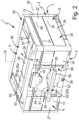
- the storage device designated overall by reference number 1, comprises one or more storage containers 2, the basic structure of which is from Figures 1 to 19 can be seen in an advantageous embodiment.
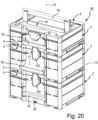
- the Figure 20 shows three storage containers 2 of the storage device 1 in a state stacked on top of one another to form a container stack 98, which are identical apart from a different height.
- the storage device 1 can in principle only contain a single storage container 2.
- the storage container 2 has a container housing 15 with preferably an at least substantially rectangular floor plan, which consists of Figures 4 and 12 is clearly visible.
- the container housing 15 has a vertical axis 16 extending between a bottom 4 and a top 5
- Axial direction defines a height direction provided with the same reference numerals. It also has a longitudinal axis 17 which is perpendicular to the vertical axis 16 and runs between a front side 6 and a rear side 7 and furthermore a transverse axis 18 which is perpendicular to both the vertical axis 16 and the longitudinal axis 17.
- the axial direction of the longitudinal axis 17 defines one with the same reference number provided longitudinal direction, while the axial direction of the transverse axis 18 defines a transverse direction of the container housing 15 provided with the same reference number.
- the dimensions in the height direction 16 determine a height
- the dimensions in the longitudinal direction 17 determine a depth
- the dimensions in the transverse direction 18 determine a width of the container housing 15.
- the container housing 15 has a housing wall 22, which is formed in the interior of the housing, for example from Figures 4 , 6 and 13 visible storage space 23 limited. Any objects to be stored can be accommodated in the storage space 23, for example tools and in particular power tools.
- the container housing 15 expediently has a lower housing part 24 and a housing cover 25 which is pivotably mounted on the lower housing part 24.
- the housing wall 22 is composed of walls of the lower housing part 24 and the housing cover 25.
- the housing wall 22 consists of a bottom wall 26 closing off the storage space 23 on the underside 4 and an outer one Edge of this bottom wall 26 is a peripheral wall 27 which projects upwards in the height direction 16.
- the peripheral wall 27 encloses the storage space 23 around the vertical axis 16, with an upper end section 21 framing an access opening 28 for the storage space 23 on its upper side opposite the bottom wall 26 . Objects can be inserted into the storage space 23 and removed from the storage space 23 through the access opening 28.
- the peripheral wall 27, which is in one piece with the bottom wall 26, is composed of a front wall 32 oriented at right angles to the vertical axis 16, a rear wall 33 opposite the front wall 32 in the longitudinal direction 17, and two side walls 34.
- the side walls 34 lie opposite each other in the transverse direction 18 and each connect the front wall 32 to the rear wall 33.
- the front wall 32 and the rear wall 33 each extend essentially in a plane perpendicular to the longitudinal axis 17.
- the side walls 34 each extend essentially in a plane perpendicular to the transverse axis 18.
- the entire peripheral wall 27 and the bottom wall 26 are formed in one piece with each other.
- the housing cover 25 is assigned to the access opening 28 and is, preferably in the area of the rear wall 33, pivotally mounted relative to the lower housing part 24 about a pivot axis 35 running in the transverse direction 18.
- the pivot bearing means 12 defining the pivot axis 35 are preferably arranged on the rear corner regions of the peripheral wall 27 which each connect a side wall 34 to the rear wall 33, in particular with only a small height distance to the access opening 28.
- the housing cover 25 can be positioned either in a closed position resting on the upper end section 21 of the peripheral wall 27 and thereby closing the access opening 28 or in various open positions pivoted more or less far upwards. In the open positions, the access opening 28 becomes accessible with a more or less large opening cross section depending on the selected opening pivot angle.
- the closed position of the housing cover 25 can expediently be releasably locked.
- suitable locking means 38 which can be operated manually, can be found, for example, in the area of the front 6 on the outside of the container housing 15.
- the locking means 38 preferably comprise a rotary latch 42 which is rotatably mounted in the area of the front 6 on the housing cover 25 about an axis of rotation 44 parallel to the longitudinal axis 17 and a locking projection 43 arranged on the outside of the front wall 32 of the lower housing part 24.
- the rotary latch 42 can be in the closed position State of the housing cover 25 can be rotated so that it is either in or out of locking engagement with the associated locking projection 43.
- the exemplary illustrated storage container 2 contains only a single storage space 23, which is closed by the housing cover 25 in an openable manner.
- at least one drawer which can be pulled out if necessary is additionally arranged in the lower housing part 24 and which provides an additional storage space provides.
- the container housing 15 has no lid on the top 5, but rather a ceiling wall formed in one piece with the peripheral wall 27, the storage container 2 being designed overall as a drawer container which can be pulled out of the container housing via one or more or has retractable drawers, the drawer spaces of which define the storage space 23 as a whole.
- a handle 52 is arranged on the container housing 15, which is referred to as the front handle 52 for better differentiation.
- the container housing 15 is composed of a lower housing part 24 and a housing cover 25 according to the exemplary embodiment
- the front handle 52 is preferably attached to the outside of the front wall 32 of the lower housing part 24. This is the case in the illustrated embodiment.
- the storage container 2 can be carried and transported in an orientation referred to below as a vertical orientation, in which the vertical axis 16 is aligned horizontally.
- the storage container 2 preferably has a further handle 45 on the outside of its top 5 oriented in the height direction 16, which is referred to as the upper handle 45 for better differentiation.
- the upper handle 45 is attached to the outside of an upper cover wall 79 of the housing cover 25 which extends at right angles to the vertical axis 16 in the closed position.
- the storage container 2 can be placed in a horizontal orientation carry and transport in which the vertical axis 16 runs vertically.
- At least the front handle 52, but preferably also the upper handle 45, are pivotally mounted on the container housing 15, so that they can be positioned by pivoting relative to the container housing 15 either in a non-use position pivoted towards the container housing 15 or in a use position projecting away from the container housing 15.
- the pivot axis 51 of the front handle 52 is referred to below as the front pivot axis 51, the associated pivoting movement 53 being indicated by a double arrow.
- the pivot axis 49 of the upper handle 45 is referred to below as the upper pivot axis 49, the associated pivoting movement 41 also being indicated by a double arrow.
- Both pivot axes 51, 49 run parallel to the transverse axis 18.
- the non-use positions of the two handles 52, 45 pivoted towards the container housing 15 are shown at 52a and 45a, the use positions at 52b and 45b.
- the front handle 52 protrudes forward from the container housing 15 in its use position 52b, while the upper handle 45 protrudes upwards from the container housing 15 in its use position 45b.
- the front handle 52 is preferably designed as an at least substantially U-shaped bow handle. Appropriate applies to the upper handle 45. In the illustrated embodiment, both handles 52, 45 are implemented as bow handles.
- the front handle 52 designed as a bow handle, has two handle legs 55 corresponding to the U-legs, spaced apart from one another in a handle longitudinal direction 54 and parallel to one another, which are connected to one another at one front end region by a connecting web 56.
- the longitudinal direction of the handle 54 runs in the axial direction of a longitudinal axis of the front handle 52 which has the same reference number.
- the upper handle 45 similarly also has two handle legs 57 which are spaced apart from one another in the longitudinal direction 18 and which are connected to one another at one end by a connecting web 58.
- the preferably rod-shaped connecting webs 56, 58 of the two handles 52, 45 expediently run parallel to one another.
- the upper handle 45 preferably has a greater length than the front handle 52.
- Both handles 52, 45 are arranged and designed mirror-symmetrically with respect to a central plane spanned by the vertical axis 16 and the longitudinal axis 17 and passing through the container housing 15 in the middle of the width.
- the upper handle 45 is pivotably mounted on the housing cover 25 in the area of the free end sections 63 of its handle legs 57 opposite its connecting web 58. In the non-use position 45a, a grip plane of the upper handle 45 spanned by the connecting web 58 and the two handle legs 57 runs at right angles to the vertical axis 16.
- the upper cover wall 79 of the housing cover 25 belonging to the housing wall 22 preferably has an upper wall recess 64 on the outside, in which the upper handle 45 is rotatably mounted and in which the upper handle 45 is preferably completely recessed when it assumes its non-use position 45a.
- the upper wall recess 64 is expediently also U-shaped. In the use position 45b, the upper handle 45 protrudes upwards from the upper wall recess 64, with the connecting web 58 being spaced sufficiently far from the upper lid end surface 48 to enable one hand to grip around it to carry the storage container 2.
- the storage container 2 can also have an upper handle 45 attached to the container housing 15 in a non-pivoting manner.
- the front handle 52 is pivotably mounted on the outside of the front wall 32 in the area of the free end sections 62 of its handle legs 55 opposite its connecting web 56 in order to carry out the pivoting movement 53.
- each free end section 62 of the two handle legs 55 is assigned a suitable pivot bearing device 65.
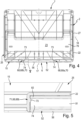
- the front wall 32 is expediently provided with a front wall recess 66 on its outside facing away from the storage space 32, in which the two pivot bearing devices 65 are arranged.
- the front wall recess 66 has such a depth that the front handle 52 is completely recessed in it when it assumes its non-use position 52a. In the use position 52b the front handle 52 protrudes sufficiently far from the front wall recess 66 to be able to grasp the connecting web 56 with one hand to carry the storage container 2.
- a handle plane spanned by the two handle legs 55 and the connecting web 56 of the front handle 52 runs at right angles to the longitudinal axis 17 in the non-use position and at right angles to the vertical axis 16 in the use position.
- the front wall recess 66 is delimited on its two sides, which are spaced apart from one another in the transverse direction 18, by two side edge surfaces 67 which face one another and are spaced apart from one another in the transverse direction 18.
- Each pivot bearing device 65 is preferably placed in the area of one of these two lateral edge surfaces 67.
- the front handle 52 is expediently pivoted downwards in the non-use position 45a, that is, its U-opening points upwards in the height direction 16.
- the non-use position 45a expediently manifests itself in the fact that the U-opening of the bow-shaped upper handle 45 points in the longitudinal direction 17 towards the back 7.
- the front handle 52 is assigned a locking device of the storage container 2, referred to as a front locking device 68 for better differentiation, which is designed for the non-pivoting, releasable locking of the front handle 52 in its non-use position 52a.
- the upper handle 45 is also assigned a locking device suitable for releasably locking its non-use position 45a, which is referred to as the upper locking device 69 for better distinction.
- the storage container 2 of the illustrated embodiment has both the front locking device 68 and the upper locking device 69.
- Each locking device 68, 69 prevents the handle 52, 45 located in the non-use position 52a, 45a from carrying out uncontrolled pivoting movements relative to the container housing 15 when the storage container 2 is used using the other handle 45 or 52 is transported.
- the front locking device 68 is expediently designed as a locking device 70, which automatically engages or disengages with a snap effect depending on the pivoting direction of the pivoting movement 53 when a corresponding actuating force is introduced into the front handle 52.
- the intensity of the latching is sufficiently high to prevent automatic latching or unlatching when the storage container 2 is handled as intended. However, it is sufficiently low to be able to cause the locking to lock or to be released simply by using the hand without any extraordinary effort.
- the upper locking device 69 is preferably also designed as a locking device 71, the functional properties of which correspond to those explained above with reference to the locking device 70.
- the front and/or upper locking device 68, 69 in a manner that can be operated separately, so that their operating state does not cause a change in the operating state simply by manually introducing force into the associated handle 52, 45.
- the described embodiment with automatic locking or unlocking solely due to a corresponding introduction of force into the associated handle 52, 45 enables particularly comfortable handling while at the same time keeping production costs low.
- the operating state assumed by the locking device 68, 69 with the non-pivotably locked non-use position 45a, 52a is also referred to below as the active operating state.
- the operating state of the locking device 68, 69 that no longer locks the non-use position is also referred to below as the inactive operating state.
- the pivot angle of the front handle 52 and/or the upper handle 45 between the non-use position 52a, 45a and the use position 52b, 45b is expediently at least substantially 90 degrees.
- Each handle 52, 45 can be pivoted within this pivoting range, in particular continuously, into any intermediate positions, none of which are locked or lockable.
- the handle 52, 45 has left the locked non-use position 52a, 45a, it can be pivoted freely at least up to the use position 52b, 45b. If the pivot bearing means are designed accordingly, the handle can be 52, 45 even pivot beyond the use position 52b, 45b.
- the locking device 68, 69 can be locally limited to a single area of the handle 52, 45 in question. However, it is considered more advantageous if the front locking device 68 and/or the upper locking device 69 consists of several, in particular exactly two, locking units 68a, 68b; 69a, 69b, which are arranged at a spatial distance from one another.
- the two locking units 68a, 68b and 69a, 69b of each locking device 68, 69 are spaced apart from one another in the axial direction of the associated pivot axis 51, 49.
- the two locking units 68a, 68b of the front locking device 68 which are also referred to below as front locking units 68a, 68b for simplicity, are each arranged in the area of one of the two handle legs 55. They are preferably located in the area of one of the two lateral edge surfaces 67 of the front wall recess 66.
- the front locking units 68a, 68b are arranged at a distance from the pivot bearing devices 65 transversely to the pivot axis 51. In particular, they are at a distance from the pivot axis 51 which corresponds to the distance of the connecting web 56 from the pivot axis 51. When viewed in the non-use position 52a of the front handle 52, both front locking units 68a, 68b are expediently located in the area of the connecting web 56.
- the locking units 69a, 69b of the upper locking device 69 are in relation to the upper handle 45 in arranged in a comparable manner to the front locking units 68a, 68b with respect to the front handle 52.
- One of the upper locking units 69a, 69b is located in the area of one of the handle legs 57, in particular in the area facing away from the other handle leg 57. They are each located in the area of one of two mutually facing side edge surfaces 72 of the upper wall recess 66, which are arranged at a distance from one another in the transverse direction 18 and which, in the exemplary embodiment, are each close to one of the two side walls 34.
- one of the handle legs 57 of the upper handle 45 extends next to each of these two side edge surfaces 72.
- the upper locking units 69a, 69b are preferably each arranged in the area of the connecting web 58 of the upper handle 45.
- Each front locking unit 68a, 68b preferably contains a locking projection 73 which is arranged on the housing wall 22 of the container housing 15 and is in particular formed in one piece with the housing wall 22 and is, for example, knob-shaped. It represents a first locking element 73a of the front locking unit 68a, 68b.
- Each locking projection 73 is preferably formed on one of the two lateral edge surfaces 67 of the front wall recess 66 so that it protrudes from the side into the front wall recess 66.
- Each upper locking unit 69a, 69b expediently also includes a correspondingly designed locking projection 75, these locking projections 75 expediently each being formed on one of the two lateral edge surfaces 72 of the upper wall recess 66.
- Each locking projection 73 of the front locking units 68a, 68b engages in the non-use position 52a in a locking recess 74 of the respective front locking unit 68a, 68b formed in the front handle 52.
- This locking recess 74 represents a second locking element 74a of the respective front locking unit 68a, 68b.
- the two locking recesses 74 in the exemplary embodiment are formed by the end regions assigned to the two handle legs 55 of a cavity 81 which passes through the connecting web 56 in its longitudinal direction.
- each locking projection 73 dips into the cavity 81 from one end face and engages behind a wall section 82 of the connecting web 56 that peripherally surrounds this cavity 81.
- the wall section 82 can be moved past the locking projections 73 with a snap effect by the pivoting movement 53 of the front handle 52.
- each upper locking unit 69a, 69b expediently also includes a locking recess 76 formed on the upper handle 45, which is formed by one of the two opposite end regions of a cavity 83 longitudinally passing through the connecting web 58 of the upper handle 45.
- the two locking projections 75 engage into the cavity 83 from opposite sides and overlap a wall section 84 of the connecting web 58 which peripherally encloses the cavity 81.
- said wall section 84 is attached to the associated one with a snap effect Locking projection 75 can be moved past.
- each locking recess 74, 76 is designed to be complementary to the shape of the locking projection 73, 75 and has, for example, the shape of a small trough into which the knob-like locking projection 73, 75 can snap.
- first and second locking elements 73a, 74a of the front handle 52 can also be designed in a way other than in the form of a locking recess and a locking projection.
- the upper locking device 69 is designed in the same way as the front locking device 68, which is achieved in the illustrated exemplary embodiment.
- the front handle 52 is pivotably fixed to the front wall 32 by means of two pivot bearing devices 65, each of which is assigned to one of the free end sections 62 of the handle legs 55.
- Each of these pivot bearing devices 65 has a first storage element 85 arranged on the container housing 15 and a second storage element 86 arranged on the handle leg 55.
- These two bearing elements 85, 86 are inserted into one another in the axial direction of the pivot axis 51 and can be rotated relative to one another.
- the pivot bearing devices 65 are preferably designed such that each second storage element 86 arranged on a handle leg 55 is plugged together in a plug-in direction with the first storage element 85 arranged on the container housing 15, which points away from the other handle leg 55 in the axial direction of the pivot axis 51.
- the second storage elements 86 are expediently designed in one piece with the handle legs and the first storage elements 85 are expediently designed in one piece with the container housing 15.
- the first bearing element 85 is designed as a bearing eye 85a, which has an insertion opening 87 facing the adjacent handle leg 57.
- the bearing eye 85a is realized in particular as a wall recess or wall recess in the front wall 32. In the exemplary embodiment, it is formed in one of the two lateral edge surfaces 67 of the front wall recess 66.
- the two insertion openings 87 face each other and are aligned coaxially with one another.
- the second bearing element 86 arranged on the front handle 52 is designed in the exemplary embodiment as a bearing pin 86a, which dips through the insertion opening 86 into the associated bearing eye 85a.
- the two bearing pins 86a are also aligned coaxially with one another, pointing in opposite directions, i.e. pointing away from one another. They are located in particular on the outer sides of the two handle legs 55 facing away from each other. This means that everyone dives Bearing pin 86a from the front wall recess 66 into the associated bearing eye 85a.
- the pivot bearing devices 65 are therefore preferably arranged in the area of the outer sides of the two handle legs 55 of the front handle 52 that face away from one another in the axial direction of the pivot axis 51.
- bearing journals 86a have, for example, a non-round cross-sectional contour. However, they can also be circular.
- the bearing pin 86a has a flattening 88 at one point on its peripheral circumference, which rests and is supported on a flat wall surface of the housing wall 22 in the use position 52b. Since the individual components are made of a plastic material, they can yield to one another when torque is applied to the front handle 52. In this respect, the use position 52b fixed by means of the bearing pins 86a can be canceled again very easily.
- the front handle 52 expediently consists of a plastic material. This preferably also applies to the upper handle 45 and the entire container housing 15.
- the front handle 52 has a tendency to bend in the sense of the two handle legs 55 moving closer together. These bending forces are in Figure 3 at 90 indicated by arrows. If the front handle 52 is not particularly stable, this can in principle result in the bearing pins 86a slipping out of the bearing eyes 85a and the container housing 15 becoming detached. This danger is particularly great when the storage room 23 is heavily loaded.
- the front handle 52 can thus be produced cost-effectively, with the possibility implemented in the exemplary embodiment in particular of making the connecting web 56 tubular as a hollow body.
- the security measures consist in that the free end section 62 of each handle leg 55 is assigned a security device 91 arranged on the storage container 2.
- Each safety device 91 is designed so that it assumes an active state at least in the use position of the front handle 51, in which it can support or supports the associated handle leg 55 in the axial direction of the pivot axis 51 with respect to the container housing 15 in order to be able to do so in the event of the Bending forces 90 prevent the two handle legs 55 from coming closer together and thus the storage elements 85, 86 inserted into one another from becoming detached from one another.
- each securing device 91 contains a first support projection 92 which is fixedly arranged on the container housing 15 in the area of the pivot axis 51 and which projects transversely and in particular at right angles to the pivot axis 51 from the front wall 32 to the front 6.
- Each safety device 91 also has a second support projection 93 arranged on the free end region 62 of the associated handle leg 55, which is arranged offset in the axial direction of the pivot axis 91 from the first support projection 92, namely offset in the direction of the outside of the assigned handle facing away from the other handle leg 55 Handle leg 55.
- the clear distance measured in the transverse direction 18 between the first support projections 92 arranged on the container housing 15 is therefore smaller than the clear distance measured in the longitudinal direction 54 between the two second support projections 93 formed on the front handle 52.
- Every second support projection 93 follows the pivoting movement 53 of the front handle 52 and is designed in such a way that it overlaps the adjacent first support projection 92 arranged on the front wall 32 of the container housing 15 at right angles to the pivot axis 51, at least during the active state of the safety device 91. Due to this overlap, the second support projection 93 can be supported with an inner support surface 94, which is formed on its end face facing the U-opening of the bow-shaped front handle 52, on an oppositely oriented outer support surface 95 of the first support projection 92 facing it.
- the safety devices 91 can be designed so that the active state is present in every pivoting position of the front handle 52.
- each safety device 91 has an inactive state in at least one other pivot position that deviates from the use position 52b of the front handle 52, in which it uses the associated handle leg 55 for a mutually directed relative movement between the two handle legs 55 in the axial direction of the pivot axis 51 releases.
- the two handle legs 55 can be elastically bending the front handle 52, in particular its connecting web 56, in the direction of the arrows 90 Figure 3 be brought closer together.
- this selective effect of the safety devices 91 is achieved by a special design of the second support projections 93 arranged on the handle legs 55. They have only a limited circumferential extent around the pivot axis 51, with their circumferential extent being approximately 90 degrees in the exemplary embodiment.
- the support projections 93 therefore assume a position that overlaps with the first support projections 92 only in the active state of the safety devices 91 ( Figure 8 ), while in other pivoting positions of the front handle 56 this overlap is eliminated ( Figure 7 ).
- the inactive state of the safety device 91 only exists when the front handle 52 is positioned in the area of the non-use position 52a, or in a limited pivoting range of the handle of a maximum of 10 degrees starting from the non-use position 52a, the non-use position 52a is included.
- Such a configuration is present in the exemplary embodiment.
- the design with a selective effect of the safety device 91 offers the possibility used in the illustrated exemplary embodiment of mounting the front handle 52 on the container housing 15 by means of a locking process and preferably also dismantling it again, while at the same time ensuring the safety function when carrying the storage container 2 by means of the front -Handle 52.
- FIG 15 the front handle 52 is shown in the dismantled state.
- Double arrows 96 indicate the possible relative movements of the two handle legs 55 in the grip plane of the front handle 52 when the front handle 52 is bent elastically.
- the front handle 52 is held in a relative position to the container housing 15, which corresponds to a pivoting position in which the safety devices 91 are inactive. In the exemplary embodiment, this is a relative position corresponding to the non-use position 52a.
- the front handle 52 is pressed against the front wall 32 of the container housing 15 with an assembly movement indicated by arrows 97 in the longitudinal direction 17, so that the second storage elements 86 are in the frame Snap into the first storage elements 85 during a latching process.
- each bearing pin 86a has an oblique sliding surface 99 on the front side, with which it can slide during the assembly movement 97 on a border structure 100 of the container housing 15 surrounding the bearing eye 85a.
- the two handle legs 55 are briefly moved towards each other according to the arrows 96 with elastic deformation in order to move away from each other again after passing the border structure 100 according to the arrows 96 and thereby snap into the bearing eyes 85a.
- the front handle 52 can be easily dismantled again by engaging a lever tool in the gap between a handle leg 55 and the side edge surface 67 and bending the associated handle leg 55 elastically in the direction of the U-opening.
- the second support projection 93 expediently delimits a first groove 101, which is formed on the front side on the free end section 62 of the handle leg 55 and is open transversely to the pivot axis 51.
- the first support projection 92 which is formed on the container housing 15, dips into this first groove 101.
- the first support projection 92 formed on the container housing 15 delimits a second groove 102, which is also open transversely to the pivot axis 91 and into which the second support projection 93 is immersed.
- the immersion of the support projections 92, 93 into the grooves 102, 101 occurs selectively to the same extent as the mutual supporting effect of the two support projections 92, 93.
- Through the grooves 101, 102 results there is even better support and/or guidance for the handle legs 55.
- An advantageous embodiment of the storage device 1 contains an in Figure 3 Shelf structure 103, indicated only schematically by dash-dotted lines, which is designed to store at least one storage container 2 when not in use.
- the shelf structure 103 offers the possibility of holding the at least one storage container 2 in a drawer-like manner.
- Such a shelf structure 103 can be installed, for example, in a workshop or in a service vehicle.
- the storage container 2 has a guide device 104 on the outside of the lower housing part 24, via which it can be brought into engagement in a detachable, linearly displaceable manner by means of an adapted counter-guide device 105 of the storage device 1 arranged on the shelf structure 103.
- the guide device 104 includes one guide rail 104a, 104b on the outside of each side wall 34 in the area of the underside 4.
- the counter-guide device 105 has two counter-guide rails 105a, 105b, which are arranged at a distance from one another on the shelf structure 103 in such a way that the Storage container 2 can be brought into engagement with them from one end side by means of its guide rails 104a, 104b.
- the guide rails 104a, 104b and the counter-guide rails 105a, 105b are coordinated with one another in such a way that the storage container 2 can be inserted into the shelf structure 103 in its longitudinal direction 17 and can be pulled out of the shelf structure 103.
- the front handle 52 can be used for this handling.
- the guide device 104 is expediently integrated in one piece into the lower housing part 24 made of plastic material.
- FIG Figure 20 a container stack 98 consisting of two or more storage containers 2 stacked on top of one another results, as shown in FIG Figure 20 is shown as an example.
- an upper container 2 sits with its underside 4 on the top 5 of another container 2 arranged underneath.
- Each storage container 2 expediently has a lower coupling device 106 in the area of its underside 4, for example in the Figure 3 is designed in an obvious manner.
- each storage container 2 has an upper coupling device 107 on the top 5, the preferred embodiment of which Figure 1 is visible.
- the two coupling devices 106, 107 are adapted to one another in such a way that, through their interaction, the storage containers 2 stacked directly on top of one another can be releasably coupled to one another in a manner that cannot be separated from one another.
- Such a coupled state is in Figure 20 shown.
- the stack of containers 98 can then be carried and transported uniformly using the upper handle 45 of the top storage container 2.
- the locking means 38 explained above preferably belong at least partially to the two coupling devices 106, 107.
- the rotary lock 22 can be in one Figure 20
- the coupling position shown at 108 can be rotated in which the two are stacked on top of each other Storage container 2 in the area of the front 6 is irremovably coupled to one another.
- Further components of the coupling devices 106, 107 are formed in the illustrated embodiment by projections formed on the underside 4 and by depressions formed on the top 5.
- the projections and recesses at least partially engage one another, overlapping or reaching behind each other transversely to the height direction 16 and also effecting a coupling of two storage containers 2 stacked on top of one another that cannot be separated from one another, in particular in the area of the back 7.
- the projections are These are expediently feet used to place the storage container 2 on a surface.
Description
Die Erfindung betrifft eine Aufbewahrungseinrichtung, mit mindestens einem Aufbewahrungsbehälter, der über ein Behältergehäuse verfügt, das an einer in einer Höhenrichtung orientierten Oberseite einen oberen Handgriff und an einer rechtwinkelig zu der Höhenrichtung orientierten Vorderseite einen um eine Schwenkachse verschwenkbar gelagerten Front-Handgriff aufweist, wobei der Front-Handgriff im Rahmen einer Schwenkbewegung wahlweise in eine vorne an das Behältergehäuse herangeschwenkte Nichtgebrauchsstellung oder in eine vom Behältergehäuse weggeschwenkte, nach vorne ragende Gebrauchsstellung verschwenkbar ist, wobei der Aufbewahrungsbehälter eine dem Front-Handgriff zugeordnete vordere Arretiervorrichtung aufweist, die zur unverschwenkbaren lösbaren Arretierung des Front-Handgriffes in dessen Nichtgebrauchsstellung ausgebildet ist.The invention relates to a storage device, with at least one storage container, which has a container housing which has an upper handle on a top side oriented in a height direction and a front handle which is pivotably mounted about a pivot axis on a front side oriented at right angles to the height direction, the Front handle can be pivoted as part of a pivoting movement either into a non-use position pivoted towards the front of the container housing or into a use position pivoted away from the container housing and projecting forward, the storage container having a front locking device assigned to the front handle, which is used for non-pivoting, releasable locking of the front -Handle is designed in its non-use position.
Eine aus der
Die
Die
Eine aus der
Die
Die
Eine aus der
Der Erfindung liegt die Aufgabe zu Grunde, Maßnahmen zu treffen, um den Handhabungskomfort für einen mit zwei Handgriffen ausgestatteten Aufbewahrungsbehälter einer Aufbewahrungseinrichtung zu verbessern.The invention is based on the object of taking measures to improve the handling comfort for a storage container of a storage device equipped with two handles.
Zur Lösung dieser Aufgabe ist erfindungsgemäß in Verbindung mit den eingangs genannten Merkmalen vorgesehen, dass der obere Handgriff ebenfalls verschwenkbar am Behältergehäuse gelagert ist, wobei er im Rahmen einer Schwenkbewegung wahlweise in eine oben an das Behältergehäuse herangeschwenkte Nichtgebrauchsstellung oder in eine vom Behältergehäuse weggeschwenkte und nach oben ragende Gebrauchsstellung verschwenkbar ist, wobei der Aufbewahrungsbehälter eine dem oberen Handgriff zugeordnete obere Arretiervorrichtung zur lösbaren Arretierung des oberen Handgriffes in seiner Nichtgebrauchsstellung aufweist.To solve this problem, it is provided according to the invention in conjunction with the features mentioned at the outset that the upper handle is also pivotably mounted on the container housing, whereby it can be pivoted, as part of a pivoting movement, either into a non-use position which is pivoted towards the top of the container housing or into a position which is pivoted away from the container housing and upwards protruding position of use can be pivoted, the storage container having an upper locking device assigned to the upper handle for releasably locking the upper handle in its non-use position.
Auf diese Weise kann der an einem Aufbewahrungsbehälter der Aufbewahrungseinrichtung vorne angebrachte Front-Handgriff in seiner an das Behältergehäuse herangeschwenkten Nichtgebrauchsstellung lösbar arretiert werden. Der Front-Handgriff ist dadurch an einem unkontrollierten Verschwenken relativ zum Behältergehäuse gehindert, wenn der Aufbewahrungsbehälter ohne Nutzung des Front-Handgriffes und insbesondere unter Verwendung des an der Oberseite angeordneten oberen Handgriffes transportiert wird. Somit kann verhindert werden, dass der Front-Handgriff unkontrolliert hin und her schwenkt und außen gegen das Behältergehäuse schlägt, wenn der Aufbewahrungsbehälter unter Nutzung des oberen Handgriffes getragen wird. Auch kann durch diese Maßnahme ausgeschlossen werden, dass der Front-Handgriff versehentlich aus der Nichtgebrauchsstellung herausschwenkt und möglicherweise aufgrund von Fertigungstoleranzen reibungsbedingt in einer vom Behältergehäuse weggeschwenkten Stellung verharrt, was beim Transport des Aufbewahrungsbehälters die Folge haben könnte, dass der Front-Handgriff an eine Möbelkante oder an einen anderen Gegenstand anstößt, sodass dieser Gegenstand und/oder der Front-Handgriff beschädigt werden könnte. Die Fixierbarkeit der Nichtgebrauchsstellung des verschwenkbaren Front-Handgriffes trägt also erheblich zu einem verbesserten Handhabungskomfort des Aufbewahrungsbehälters bei. Auch der obere Handgriff ist verschwenkbar am Behältergehäuse gelagert und kann im Rahmen einer Schwenkbewegung wahlweise in eine oben an das Behältergehäuse herangeschwenkte Nichtgebrauchsstellung oder in eine vom Behältergehäuse weggeschwenkte und nach oben ragende Gebrauchsstellung verschwenkt werden. Auch dem oberen Handgriff ist eine zur lösbaren Arretierung der Nichtgebrauchsstellung geeignete Arretiervorrichtung zugeordnet, die zur besseren Unterscheidung von der vorderen Arretiervorrichtung als obere Arretiervorrichtung bezeichnet wird.In this way, the front handle attached to the front of a storage container of the storage device can be in can be releasably locked in its non-use position when pivoted towards the container housing. The front handle is thereby prevented from uncontrolled pivoting relative to the container housing when the storage container is transported without using the front handle and in particular using the upper handle arranged on the top. This can prevent the front handle from swinging back and forth uncontrollably and hitting the outside of the container housing when the storage container is carried using the upper handle. This measure can also prevent the front handle from accidentally swinging out of the non-use position and possibly remaining in a position pivoted away from the container housing due to friction due to manufacturing tolerances, which could result in the front handle hitting the edge of a furniture when the storage container is being transported or collides with another object that could damage that object and/or the front handle. The ability to fix the non-use position of the pivoting front handle contributes significantly to improved handling comfort of the storage container. The upper handle is also pivotably mounted on the container housing and can be pivoted as part of a pivoting movement either into a non-use position which is pivoted towards the top of the container housing or into a use position which is pivoted away from the container housing and projects upwards. The upper handle is also assigned a locking device suitable for releasably locking the non-use position, which is referred to as the upper locking device to better distinguish it from the front locking device.
Der in der Nichtgebrauchsstellung arretierte obere Handgriff wird am Wegschwenken vom Behältergehäuse gehindert, wenn das Behältergehäuse durch Nutzung des Front-Handgriffes mit horizontal ausgerichteter Hochachse getragen wird. Insoweit stellen sich hier die gleichen Vorteile ein, die weiter oben im Zusammenhang mit dem arretierbaren Front-Handgriff im Zusammenhang mit einer Nutzung des oberen Handgriffes als Traggriff erläutert wurden.The upper handle, which is locked in the non-use position, is prevented from swinging away from the container housing when the container housing is carried using the front handle with the vertical axis aligned horizontally. In this respect, the same advantages apply here that were explained above in connection with the lockable front handle in connection with using the upper handle as a carrying handle.
Vorteilhafte Weiterbildungen der Erfindung gehen aus den Unteransprüchen hervor.Advantageous developments of the invention emerge from the subclaims.
Die an der Vorderseite des Behältergehäuses angeordnete und deshalb als vordere Arretiervorrichtung bezeichnete Arretiervorrichtung ist insbesondere so ausgebildet, dass sie selbsttätig in einen den Front-Handgriff unverschwenkbar am Behältergehäuse arretierenden aktiven Betriebszustand gelangt, wenn der Front-Handgriff bewusst aus der Gebrauchsstellung in die Nichtgebrauchsstellung verschwenkt wird. Einer gesonderten Betätigung der Arretiervorrichtung bedarf es dabei nicht.The locking device, which is arranged on the front of the container housing and is therefore referred to as the front locking device, is designed in particular in such a way that it automatically enters an active operating state that locks the front handle non-pivotably on the container housing, when the front handle is deliberately pivoted from the use position to the non-use position. There is no need to operate the locking device separately.
Zweckmäßigerweise erfolgt auch das Entarretieren des Front-Handgriffes selbsttätig, sobald der Front-Handgriff durch eine manuelle Krafteinleitung aus der Nichtgebrauchsstellung in Richtung der Gebrauchsstellung verschwenkt wird. Auch hier ist es nicht erforderlich, die Arretiervorrichtung gesondert durch einen speziellen Deaktivierungshandgriff in den nicht mehr arretierend wirkenden inaktiven Betriebszustand zu versetzen.The front handle is expediently unlocked automatically as soon as the front handle is pivoted from the non-use position towards the use position by manual force application. Here, too, it is not necessary to separately set the locking device into the inactive operating state, which no longer has a locking effect, using a special deactivation handle.
In beiden vorgenannten Fällen erfolgen also das Arretieren und das Lösen der Arretierung quasi automatisch, wenn der Nutzer der Aufbewahrungseinrichtung den Front-Handgriff erfasst und durch entsprechenden Kraftaufwand in der Richtung der Nichtgebrauchsstellung oder in der Richtung der Gebrauchsstellung verschwenkt.In both of the aforementioned cases, the locking and releasing of the locking take place virtually automatically when the user of the storage device grasps the front handle and pivots it in the direction of the non-use position or in the direction of the use position by applying appropriate force.
Insbesondere in dem vorgenannten Zusammenhang ist es vorteilhaft, wenn die vordere Arretiervorrichtung als eine abhängig von der Schwenkrichtung des Front-Handgriffes mit einem Schnappeffekt selbsttätig einrastende oder selbsttätig ausrastende Rastvorrichtung ausgebildet ist. Eine solche Rastvorrichtung ist kostengünstig realisierbar und lässt sich zweckmäßigerweise unmittelbar bei der Fertigung des Behältergehäuses und des Front-Handgriffes in diese Behälterkomponenten integrieren.Particularly in the aforementioned context, it is advantageous if the front locking device is designed as a locking device that automatically engages or automatically disengages with a snap effect depending on the pivoting direction of the front handle. Such a locking device can be implemented cost-effectively and can expediently be integrated into these container components directly during the production of the container housing and the front handle.
Als besonders zweckmäßig wird es erachtet, wenn die vordere Arretiervorrichtung eine oder mehrere Arretiereinheiten aufweist, die zur besseren Unterscheidung jeweils als vordere Arretiereinheit bezeichnet werden. Die Arretiervorrichtung kann beispielsweise nur eine einzige solche vordere Arretiereinheit umfassen, verfügt jedoch zweckmäßigerweise über zwei derartige vordere Arretiereinheiten, die in der Achsrichtung der Schwenkachse des Front-Handgriffes mit Abstand zueinander angeordnet sind. Vorzugsweise ist jedem in der Achsrichtung der Schwenkachse weisenden Endabschnitt des Front-Handgriffes eine eigene vordere Arretiereinheit zugeordnet. Auf diese Weise wird der Front-Handgriff besonders sicher in seiner Nichtgebrauchsstellung gehalten.It is considered particularly useful if the front locking device has one or more locking units, which are each referred to as a front locking unit for better differentiation. The locking device can, for example, only include a single such front locking unit, but expediently has two such front locking units, which are arranged at a distance from one another in the axial direction of the pivot axis of the front handle. Preferably, each end section of the front handle pointing in the axial direction of the pivot axis is assigned its own front locking unit. In this way, the front handle is held particularly securely in its non-use position.
Jede vordere Arretiereinheit hat ein am Behältergehäuse angeordnetes erstes Arretierelement und ein mit diesem ersten Arretierelement zusammenwirkendes, am Front-Handgriff angeordnetes zweites Arretierelement. Das zweite Arretierelement macht die Schwenkbewegung des Front-Handgriffes mit. In der Nichtgebrauchsstellung des Front-Handgriffes überlappen sich das erste und zweite Arretierelement in der Achsrichtung der Schwenkachse und somit quer zur Richtung der Schwenkbewegung. Durch dieses sich Hintergreifen der beiden Arretierelemente wird der Front-Handgriff formschlüssig an einem Verschwenken um die Schwenkachse gehindert. Befindet sich der Front-Handgriff in der Gebrauchsstellung, ist der vorgenannte gegenseitige Eingriff der ersten und zweiten Arretierelemente aufgehoben und der Front-Handgriff kann ungehindert verschwenkt werden.Each front locking unit has a first locking element arranged on the container housing and a second locking element which cooperates with this first locking element and is arranged on the front handle. The second locking element follows the pivoting movement of the front handle. In the non-use position of the front handle, the first and second locking elements overlap in the axial direction of the pivot axis and thus transversely to the direction of the pivot movement. By gripping behind the two locking elements, the front handle is positively prevented from pivoting about the pivot axis. If the front handle is in the position of use, the aforementioned mutual engagement of the first and second locking elements is canceled and the front handle can be pivoted unhindered.
Bevorzugt ist das am Behältergehäuse angeordnete erste Arretierelement als ein in der Achsrichtung der Schwenkachse ragender Arretiervorsprung ausgebildet, der bevorzugt einstückig mit der Gehäusewand des Behältergehäuses ausgebildet ist. Das mit diesem Arretiervorsprung kooperierende zweite Arretierelement ist vorzugsweise als eine am Front-Handgriff vorgesehene Arretiervertiefung ausgebildet, in die der Arretiervorsprung im aktiven Betriebszustand der Arretiervorrichtung eingreift, insbesondere in formschlüssiger Weise. Auch eine vertauschte Anordnung von Arretiervorsprung und Arretiervertiefung ist möglich.The first locking element arranged on the container housing is preferably designed as a locking projection projecting in the axial direction of the pivot axis, which is preferably designed in one piece with the housing wall of the container housing. The second locking element cooperating with this locking projection is preferably designed as a locking recess provided on the front handle, into which the locking projection intervenes in the active operating state of the locking device, in particular in a positive manner. A swapped arrangement of the locking projection and locking recess is also possible.
Der Front-Handgriff kann aus Gründen der Gewichtsersparnis zumindest partiell als Hohlkörper ausgebildet sein. Dies trifft insbesondere auf einen zum Tragen des Aufbewahrungsbehälters mit einer Hand umgreifbaren Bestandteil des Front-Handgriffes zu. Bevorzugt kann dann der sowieso vorhandene Hohlraum als Arretiervertiefung der Arretiereinheit genutzt werden. Handelt es sich um einen als Bügelgriff ausgebildeten Front-Handgriff, ist der den Hohlraum aufweisende Bestandteil insbesondere von einem sich zwischen zwei Griffschenkeln erstreckenden Verbindungssteg gebildet.To save weight, the front handle can be at least partially designed as a hollow body. This applies in particular to a component of the front handle that can be grasped with one hand to carry the storage container. The existing cavity can then preferably be used as a locking recess of the locking unit. If it is a front handle designed as a bow handle, the component having the cavity is formed in particular by a connecting web extending between two handle legs.
Die Arretiervorrichtung ist insbesondere so ausgebildet, dass sie den Front-Handgriff ausschließlich in der Nichtgebrauchsstellung unverschwenkbar blockiert. In allen außerhalb der Nichtgebrauchsstellung liegenden Schwenkstellungen des Front-Handgriffes, die die Gebrauchsstellung mit einschließen, ist der Front-Handgriff zweckmäßigerweise frei verschwenkbar und die Arretiervorrichtung ist inaktiv. Folglich kann der Front-Handgriff trotz der vorhandenen Arretiermöglichkeit ungehindert mit einem großen Schwenkwinkel verschwenkt werden, der beispielsweise nur wenig kleiner ist als 90 Grad. Dies hat zur Folge, dass der Front-Handgriff zur Handhabung des Aufbewahrungsbehälters praktisch uneingeschränkt in gleicher Weise nutzbar ist wie ein Front-Handgriff, der keine vordere Arretiervorrichtung aufweist.The locking device is designed in particular in such a way that it blocks the front handle in a non-pivoting manner only in the non-use position. In all pivot positions of the front handle that are outside the non-use position and include the use position, the front handle can expediently be freely pivoted and the locking device is inactive. Consequently, despite the existing locking option, the front handle can be swiveled freely with a large swivel angle, which is, for example, only slightly smaller than 90 degrees. The result of this is that the front handle for handling the storage container can be used practically without restriction in the same way as a front handle that does not have a front locking device.
Es besteht grundsätzlich die Möglichkeit, zusätzliche Maßnahmen vorzusehen, die den Front-Handgriff auch in der Gebrauchsstellung lösbar fixieren. Dann bleibt der Front-Handgriff beim Loslassen in der Gebrauchsstellung stehen und lässt sich bei einer anschließenden Nutzung besonders einfach ergreifen.In principle, it is possible to provide additional measures that also keep the front handle in the position of use fix releasably. The front handle then remains in the position of use when it is released and is particularly easy to grasp when used afterwards.
Der Front-Handgriff ist am Behältergehäuse bevorzugt mittels mindestens einer die Schwenkachse definierenden Schwenklagereinrichtung verschwenkbar gelagert. Dem Front-Handgriff können nur eine solche Schwenklagereinrichtung oder mehrere, insbesondere genau zwei solche Schwenklagereinrichtungen zugeordnet sein. Mehrere Schwenklagereinrichtungen sind zweckmäßigerweise in der Achsrichtung der Schwenkachse beabstandet zueinander angeordnet.The front handle is pivotably mounted on the container housing preferably by means of at least one pivot bearing device defining the pivot axis. Only one such pivot bearing device or several, in particular exactly two, such pivot bearing devices can be assigned to the front handle. Several pivot bearing devices are expediently arranged at a distance from one another in the axial direction of the pivot axis.
Als besonders vorteilhaft wird es angesehen, wenn die vordere Arretiervorrichtung in einer zur Schwenkachse des Front-Handgriffes rechtwinkeligen Richtung beabstandet zu der mindestens einen Schwenklagereinrichtung angeordnet ist. Dadurch ist ein etwas höherer Kraftaufwand zum Arretieren und Endarretieren erforderlich, was unbeabsichtigten Betätigungen der Arretiervorrichtung entgegenwirkt. Es ist gleichwohl durchaus möglich, die vordere Arretiervorrichtung der unmittelbaren Nachbarschaft der Schwenkachse anzuordnen. Dies hat den Vorteil, dass in Verbindung mit einer Rastvorrichtung ein relativ großer Hebelarm für das Entrasten und Verrasten zur Verfügung steht.It is considered particularly advantageous if the front locking device is arranged at a distance from the at least one pivot bearing device in a direction perpendicular to the pivot axis of the front handle. This means that a slightly higher amount of force is required for locking and final locking, which counteracts unintentional actuation of the locking device. However, it is certainly possible to arrange the front locking device in the immediate vicinity of the pivot axis. This has the advantage that, in conjunction with a locking device, a relatively large lever arm is available for unlocking and locking.
Der verschwenkbare Front-Handgriff ist zweckmäßigerweise bügelförmig mit zumindest im Wesentlichen U-förmiger Gestalt ausgebildet, sodass er als Bügelgriff bezeichnet werden kann. Er hat zwei den beiden U-Schenkeln entsprechende Griffschenkel, die durch einen Verbindungssteg zur Bildung der U-Struktur miteinander verbunden sind. Jeder Griffschenkel ist im Bereich seines dem Verbindungssteg entgegengesetzten freien Endabschnittes über jeweils eine Schwenklagereinrichtung in verschwenkbarer Weise am Behältergehäuse gelagert.The pivotable front handle is expediently bow-shaped with at least a substantially U-shaped shape, so that it can be referred to as a bow handle. It has two handle legs corresponding to the two U-legs, which are connected to each other by a connecting web to form the U-structure. Each handle shank is in the area of its free end section opposite the connecting web via a pivot bearing device in a pivotable manner on the container housing.
In Verbindung mit einem solchen Bügelgriff ist es vorteilhaft, wenn die vordere Arretiervorrichtung im Bereich des Verbindungssteges angeordnet ist, wenn man den Aufbewahrungsbehälter in der Nichtgebrauchsstellung des Front-Handgriffes betrachtet. Die ersten und zweiten Arretierelemente jeder optional vorhandenen vorderen Arretiereinheit der Arretiervorrichtung sind hier zur Schwenkachse des Front-Handgriffes beabstandet im Bereich des Verbindungssteges angeordnet. Der Hohlraum eines hohlen Verbindungssteges kann, wie oben schon erwähnt, als Arretiervertiefung genutzt werden. Grundsätzlich kann die am Front-Handgriff ausgebildete Komponente der Arretiervorrichtung beispielsweise auch an einem der Griffschenkel ausgebildet sein.In conjunction with such a bow handle, it is advantageous if the front locking device is arranged in the area of the connecting web when the storage container is viewed in the non-use position of the front handle. The first and second locking elements of each optional front locking unit of the locking device are arranged here at a distance from the pivot axis of the front handle in the area of the connecting web. The cavity of a hollow connecting web can, as already mentioned above, be used as a locking recess. In principle, the component of the locking device formed on the front handle can also be formed, for example, on one of the handle legs.
Jede der beiden einem als Bügelgriff ausgebildeten Front-Handgriff zugeordneten Schwenklagereinrichtungen hat zweckmäßigerweise zwei in der Achsrichtung der Schwenkachse ineinander eingesteckte und relativ zueinander drehbare erste und zweite Lagerungselemente. Eines dieser Lagerungselemente befindet sich jeweils am Behältergehäuse, das andere am freien Endabschnitt eines der beiden Griffschenkel des Front-Handgriffes. Das am Behältergehäuse ausgebildete erste Lagerungselement ist bevorzugt als ein Lagerauge konzipiert, in das das bevorzugt als Lagerzapfen ausgebildete zweite Lagerungselement von der der jeweils anderen Schwenklagereinrichtung zugewandten Seite her eingesteckt ist.Each of the two pivot bearing devices assigned to a front handle designed as a bow handle expediently has two first and second bearing elements which are inserted into one another in the axial direction of the pivot axis and can be rotated relative to one another. One of these storage elements is located on the container housing, the other on the free end section of one of the two handle legs of the front handle. The first bearing element formed on the container housing is preferably designed as a bearing eye, into which the second bearing element, preferably formed as a bearing pin, is inserted from the side facing the other pivot bearing device.
Um sicherzustellen, dass der als Bügelgriff ausgebildete Front-Handgriff selbst beim Tragen eines schweren Aufbewahrungsbehälters nicht unbeabsichtigt aus dem Behältergehäuse herausrutscht und der Aufbewahrungsbehälter herunterfällt, ist zweckmäßigerweise dem freien Endabschnitt jedes Griffschenkels eine zumindest in der Gebrauchsstellung des Front-Handgriffes einen aktiven Zustand einnehmende Sicherungseinrichtung zugeordnet. Die Sicherungseinrichtung stützt in ihrem aktiven Zustand den ihr zugeordneten Griffschenkel in der Achsrichtung der Schwenkachse bezüglich dem Behältergehäuse derart ab, dass sich der Griffschenkel nicht in Richtung zum anderen Griffschenkel bewegen kann. Dadurch können die ineinander eingesteckten Lagerungselemente der Schwenklagereinrichtungen keine axiale Relativbewegung ausführen, durch die sie auseinandergezogen und voneinander getrennt werden, wenn die Griffschenkel des Handgriffes durch im Sinne einer gegenseitigen Annäherung wirkende äußere Kräfte beaufschlagt werden. Solche äußeren Kräfte können beispielsweise entstehen, wenn ein schwer beladener Aufbewahrungsbehälter am Verbindungssteg seines Handgriffes angehoben wird und sich der Handgriff im Bereich des Verbindungssteges elastisch durchbiegt Durch die Abstützung mittels der Sicherungseinrichtungen wird verhindert, dass sich die Griffschenkel durch elastisches Verformen des Front-Handgriffes aneinander annähern, wenn der Aufbewahrungsbehälter am Verbindungssteg seines Front-Handgriffes angehoben wird.To ensure that the front handle, designed as a bow handle, even when carrying a heavy storage container does not accidentally slip out of the container housing and the storage container falls down, a safety device which assumes an active state at least in the use position of the front handle is expediently assigned to the free end section of each handle leg. In its active state, the safety device supports the handle leg assigned to it in the axial direction of the pivot axis with respect to the container housing in such a way that the handle leg cannot move in the direction of the other handle leg. As a result, the storage elements of the pivot bearing devices inserted into one another cannot carry out an axial relative movement by which they are pulled apart and separated from one another when the handle legs of the handle are acted upon by external forces acting in the sense of a mutual approach. Such external forces can arise, for example, when a heavily loaded storage container is lifted at the connecting bar of its handle and the handle bends elastically in the area of the connecting bar. The support by means of the safety devices prevents the handle legs from coming closer to one another due to elastic deformation of the front handle when the storage container is lifted using the connecting bar of its front handle.
Bevorzugt sind die Schwenklagereinrichtungen so ausgebildet, dass jedes an einem Griffschenkel angeordnete zweite Lagerungselement in einer Steckrichtung mit dem am Behältergehäuse angeordneten ersten Lagerungselement zusammengesteckt ist, die in der Achsrichtung der Schwenkachse vom jeweils anderen Griffschenkel wegweist. Zweckmäßigerweise sind die zweiten Lagerungselemente einstückig mit den Griffschenkeln ausgebildet und die ersten Lagerungselemente sind zweckmäßigerweise einstückig mit dem Behältergehäuse ausgebildet.The pivot bearing devices are preferably designed in such a way that each second storage element arranged on a handle leg is plugged together in a plug-in direction with the first storage element arranged on the container housing, which points away from the other handle leg in the axial direction of the pivot axis. The second storage elements are expediently designed in one piece with the handle legs and the first storage elements are expediently formed in one piece with the container housing.
Der Front-Handgriff ist an dem Behältergehäuse zweckmäßigerweise durch einen Rastvorgang montiert, der mit einem elastischen Verbiegen des Front-Handgriffes einhergeht, bei dem sich die beiden Griffschenkel kurzzeitig aneinander annähern. Damit eine solche Rastmontage ungeachtet der durch die Sicherungseinrichtungen gesicherten Gebrauchsstellung möglich ist, kann der Front-Handgriff zweckmäßigerweise in mindestens einer von der Gebrauchsstellung abweichenden Schwenkstellung positioniert werden, in der die Sicherungseinrichtungen inaktiv sind und die Griffschenkel derart freigegeben sind, dass selbige aufeinander zu gerichtet bewegbar sind. Dadurch ist eine für den mit einem Rastvorgang kombinierten Montagevorgang erforderliche Relativbewegung zwischen den beiden Griffschenkeln in der Achsrichtung der Schwenkachse möglich.The front handle is expediently mounted on the container housing by a latching process, which is accompanied by an elastic bending of the front handle, in which the two handle legs briefly approach each other. So that such a locking assembly is possible regardless of the position of use secured by the safety devices, the front handle can expediently be positioned in at least one pivoting position that deviates from the position of use, in which the safety devices are inactive and the handle legs are released in such a way that they can be moved towards each other are. This enables a relative movement between the two handle legs in the axial direction of the pivot axis required for the assembly process combined with a latching process.
Bevorzugt kann der Front-Handgriff in der mit einem inaktiven Zustand der Sicherungseinrichtungen kombinierten mindestens einen Schwenkstellung bei Bedarf auch wieder vom Behältergehäuse demontiert werden. Die Griffschenkel müssen dann, beispielsweise unterstützt durch ein angesetztes Hebelwerkzeug, lediglich so weit elastisch zur Seite gebogen werden, dass die Lagerungselemente außer Eingriff miteinander gelangen.Preferably, the front handle can also be removed from the container housing again if necessary in the at least one pivoting position combined with an inactive state of the safety devices. The handle legs then only have to be bent elastically to the side, for example supported by an attached lever tool, to such an extent that the bearing elements come out of engagement with one another.
Bevorzugt kann der Front-Handgriff in jeder Schwenkstellung, in der die Sicherungseinrichtungen inaktiv sind, bei der Erstmontage des Aufbewahrungsbehälters oder in einem Reparaturfall am Behältergehäuse durch Verrastung angebracht werden. Handelt es sich um eine lösbare Rastverbindung, was vorteilhaft ist, kann der Front-Handgriff im in jede diese Schwenkstellungen verschwenkten Zustand bei Bedarf auch wieder durch einen Ausrastvorgang vom Behältergehäuse entfernt werden.Preferably, the front handle can be attached to the container housing by latching in any pivoting position in which the safety devices are inactive, during the initial assembly of the storage container or in the event of repairs. If it is a releasable locking connection, which is advantageous, the front handle can be pivoted into any of these pivoting positions again if necessary removed from the container housing by disengaging it.
Zweckmäßigerweise ist jede Sicherungseinrichtung so ausgebildet, dass ihr inaktiver Zustand zumindest im Bereich der Nichtgebrauchsstellung des Front-Handgriffes vorliegt, wobei sie vorzugsweise ausschließlich im Bereich der Nichtgebrauchsstellung des Front-Handgriffes vorliegt. Letzteres bietet eine optimale Sicherheit gegen ein versehentliches Lösen der Rastverbindung unabhängig davon, in welche Schwenkstellung außerhalb der Nichtgebrauchsstellung der Front-Handgriff momentan verschwenkt ist.Each safety device is expediently designed so that its inactive state is present at least in the area of the non-use position of the front handle, preferably exclusively in the area of the non-use position of the front handle. The latter offers optimal security against accidental loosening of the locking connection, regardless of which pivot position the front handle is currently pivoted to outside of the non-use position.
Das Behältergehäuse verfügt zweckmäßigerweise über eine Gehäusewand, in der außen an der Vorderseite eine vordere Wandvertiefung ausgebildet ist, in der der Front-Handgriff schwenkbar gelagert ist. Ist der Front-Handgriff in die Nichtgebrauchsstellung verschwenkt, liegt er zweckmäßigerweise vollständig versenkt in dieser vorderen Wandvertiefung, aus der er allerdings in der Gebrauchsstellung herausragt. Dadurch ist der Front-Handgriff bei Nichtgebrauch gegen äußere Einwirkungen gut abgeschirmt.The container housing expediently has a housing wall in which a front wall recess is formed on the outside on the front, in which the front handle is pivotally mounted. If the front handle is pivoted into the non-use position, it is expediently completely recessed in this front wall recess, from which it protrudes in the use position. This means that the front handle is well shielded from external influences when not in use.
Die obere Arretiervorrichtung ist zweckmäßigerweise als eine Rastvorrichtung ausgebildet.The upper locking device is expediently designed as a locking device.
Vorteilhaft ist es, wenn die obere Arretiervorrichtung gleichartig wie die vordere Arretiervorrichtung ausgebildet ist und somit nach dem gleichen Prinzip arbeitet. Dies erlaubt eine besonders kostengünstige Fertigung des Aufbewahrungsbehälters.It is advantageous if the upper locking device is designed in the same way as the front locking device and therefore works according to the same principle. This allows the storage container to be manufactured particularly cost-effectively.
Der obere Handgriff ist zweckmäßigerweise in der Nichtgebrauchsstellung vollständig versenkt in einer oberen Wandvertiefung aufgenommen, die außen in der Oberseite der Gehäusewand ausgebildet ist. Dies hat zum einen den Vorteil, dass der obere Handgriff bei der Nutzung des Front-Handgriffes als Tragegriff nicht über die Außenkontur des Behältergehäuses vorsteht. Zum anderen ist damit der Vorteil verbunden, dass sich der Aufbewahrungsbehälter mit weiteren Aufbewahrungsbehältern standsicher in der Höhenrichtung aufeinander stapeln lässt.The upper handle is expediently completely recessed in an upper wall recess when not in use recorded, which is formed outside in the top of the housing wall. On the one hand, this has the advantage that the upper handle does not protrude beyond the outer contour of the container housing when the front handle is used as a carrying handle. On the other hand, this has the advantage that the storage container can be stably stacked on top of one another in the height direction with other storage containers.
Bevorzugt hat das Behältergehäuse einen zumindest im Wesentlichen rechteckigen Grundriss. Dies begünstigt eine platzsparende Lagerung des Aufnahmebehälters, insbesondere auch in Fällen, in denen die Aufbewahrungseinrichtung über mehrere Aufbewahrungsbehälter verfügt.The container housing preferably has an at least essentially rectangular floor plan. This promotes space-saving storage of the receptacle, especially in Cases where the storage facility has multiple storage containers.
Bevorzugt setzt sich das Behältergehäuse aus einem kistenförmigen Gehäuseunterteil und einem Gehäusedeckel zusammen. Das Gehäuseunterteil hat an einer in der Höhenrichtung nach oben weisenden Oberseite eine Zugriffsöffnung für einen internen Aufbewahrungsraum, dem der Gehäusedeckel zugeordnet ist. Der Gehäusedeckel ist derart verschwenkbar an dem Gehäuseunterteil gelagert, dass er wahlweise in eine die Zugriffsöffnung abdeckende Schließstellung und in mindestens eine die Zugriffsöffnung freigebende Offenstellung verschwenkbar ist. Durch die freigegebene Zugriffsöffnung hindurch können Objekte in den Aufbewahrungsraum eingelagert und auch wieder herausgenommen werden. Das Gehäuseunterteil verfügt zweckmäßigerweise über eine Bodenwand und über eine vom Rand der Bodenwand in der Höhenrichtung des Behältergehäuses hochragende periphere Umfangswand, die beide zur Gehäusewand des Behältergehäuses gehören. Der obere Endabschnitt der Umfangswand umrahmt die Zugriffsöffnung.The container housing is preferably composed of a box-shaped lower housing part and a housing cover. The lower housing part has an access opening for an internal storage space on a top side pointing upwards in the height direction, to which the housing cover is assigned. The housing cover is pivotably mounted on the lower housing part in such a way that it can be pivoted either into a closed position covering the access opening and into at least one open position releasing the access opening. Objects can be stored in the storage space and removed again through the released access opening. The lower housing part expediently has a bottom wall and a peripheral peripheral wall which projects up from the edge of the bottom wall in the height direction of the container housing, both of which belong to the housing wall of the container housing. The upper end portion of the peripheral wall frames the access opening.
Der obere Handgriff ist oben außen an dem Gehäusedeckel angeordnet, während der Front-Handgriff außen an einer Vorderwand des Gehäuseunterteils angebracht ist, die ein Bestandteil der von der Bodenwand des Gehäuseunterteils hochragenden Umfangswand des Gehäuseunterteils ist.The upper handle is arranged at the top outside of the housing cover, while the front handle is attached to the outside of a front wall of the lower housing part, which is a component of the peripheral wall of the lower housing part which projects up from the bottom wall of the lower housing part.
Vorzugsweise ist das Behältergehäuse so ausgebildet, dass der Gehäusedeckel in der Schließstellung mit dem Gehäuseunterteil lösbar verriegelbar ist. Entsprechende Verriegelungsmittel befinden sich zweckmäßigerweise außen an der Vorderseite des Behältergehäuses, insbesondere in der Höhenrichtung oberhalb des Front-Handgriffes. Die Verriegelungsmittel enthalten beispielsweise einen Drehriegel.Preferably, the container housing is designed such that the housing cover can be releasably locked to the lower housing part in the closed position. Corresponding locking means are expediently located on the outside of the front of the container housing, in particular above in the height direction of the front handle. The locking means contain, for example, a rotary latch.
In einer vorteilhaften Ausgestaltung umfasst die Aufbewahrungseinrichtung eine Regalstruktur, in der der mindestens eine Aufbewahrungsbehälter während seines Nichtgebrauchs in herausziehbarer Weise aufnehmbar ist. In diesem Zusammenhang ist es von Vorteil, wenn der Aufbewahrungsbehälter an der Außenseite des Behältergehäuses eine Führungseinrichtung aufweist, die mit einer an der Regalstruktur angeordneten, ebenfalls zu der Aufbewahrungseinrichtung gehörenden Gegen-Führungseinrichtung zusammenpasst. Bevorzugt sind sowohl die Führungseinrichtung als auch die Gegen-Führungseinrichtung schienenartig strukturiert und greifen linear verschiebbar ineinander ein, was ein leichtgängiges Herausziehen oder Einschieben des Aufbewahrungsbehälters aus der Regalstruktur heraus beziehungsweise in die Regalstruktur hinein begünstigt.In an advantageous embodiment, the storage device comprises a shelf structure in which the at least one storage container can be accommodated in a pull-out manner when not in use. In this context, it is advantageous if the storage container has a guide device on the outside of the container housing, which fits together with a counter-guide device arranged on the shelf structure and also belonging to the storage device. Both the guide device and the counter-guide device are preferably structured in a rail-like manner and engage in one another in a linearly displaceable manner, which facilitates the storage container being easily pulled out or pushed in or out of the shelf structure or into the shelf structure.
Die Aufbewahrungseinrichtung kann nur einen einzigen Aufbewahrungsbehälter enthalten. Vorteilhaft ist es jedoch, wenn sie mehrere Aufbewahrungsbehälter umfasst, die bevorzugt in der Höhenrichtung jedes Aufbewahrungsbehälters aufeinander stapelbar sind. Sie können dadurch platzsparend gelagert werden.The storage facility can only contain a single storage container. However, it is advantageous if it comprises several storage containers, which can preferably be stacked on top of one another in the height direction of each storage container. This means they can be stored to save space.
Es ist vorteilhaft, wenn jeder der mehreren stapelbar Aufbewahrungsbehälter an seinem Behältergehäuse im Bereich der Unterseite eine untere Kopplungseinrichtung und im Bereich der Oberseite eine obere Kopplungseinrichtung aufweist, wobei diese beiden Kopplungseinrichtungen derart aneinander angepasst sind, dass in einer Höhenrichtung unmittelbar aufeinandergestapelte Aufbewahrungsbehälter durch Zusammenwirken der oberen Kopplungseinrichtung des jeweils unteren Aufbewahrungsbehälters und der unteren Kopplungseinrichtung des jeweils oberen Aufbewahrungsbehälters in voneinander unabhebbarer Weise lösbar miteinander koppelbar sind.It is advantageous if each of the several stackable storage containers has a lower coupling device on its container housing in the area of the underside and an upper coupling device in the area of the top, these two coupling devices being adapted to one another in such a way that storage containers stacked directly on top of one another in a height direction interact the upper coupling device of the respective lower storage container and the lower coupling device of the respective upper storage container can be releasably coupled to one another in a manner that cannot be detached from one another.
Wenn die Aufbewahrungsbehälter ein Gehäuseunterteil und einen diesbezüglich verschwenkbaren Gehäusedeckel aufweisen, wobei diese beiden Komponenten durch Verriegelungsmittel in einer Schließstellung des Gehäusedeckels lösbar miteinander verriegelbar sind, ist es vorteilhaft, wenn die Verriegelungsmittel eine Mehrfachfunktion erfüllen und auch als Bestandteile mindestens einer der Kopplungseinrichtungen ausgebildet sind.If the storage containers have a lower housing part and a housing cover that can be pivoted in this regard, these two components being releasably lockable to one another by locking means in a closed position of the housing cover, it is advantageous if the locking means fulfill a multiple function and are also designed as components of at least one of the coupling devices.
Nachfolgend wird die Erfindung anhand der beiliegenden Zeichnung näher erläutert. In dieser zeigen:
- Figur 1
- eine bevorzugte erste Ausführungsform der erfindungsgemäßen Aufbewahrungseinrichtung mit einem perspektivisch abgebildeten Aufbewahrungsbehälter, der mit der Schließstellung seines Gehäusedeckels abgebildet ist und der über zwei alternativ nutzbare Handgriffe verfügt, die in ihrer Nichtgebrauchsstellung gezeigt sind, wobei zu jedem Handgriff strichpunktiert seine Gebrauchsstellung angedeutet ist,
Figur 2- den Aufbewahrungsbehälter aus
Figur 1 im in die Gebrauchsstellung verschwenkten Zustand seines an der Vorderseite befindlichen, als Front-Handgriff ausgebildeten Handgriffes, - Figur 3
- eine Vorderansicht des Aufbewahrungsbehälters aus
Figur 1 mit Blickrichtung gemäß Pfeil III ausFigur 1 , Figur 4- einen horizontalen Schnitt durch den Aufbewahrungsbehälter mit nach oben in Richtung zum Gehäusedeckel gerichteter Blickrichtung gemäß Schnittebene IV-IV aus
Figur 3 , Figur 5- das in
Figur 4 Figur 6- einen vertikalen Schnitt des Aufbewahrungsbehälters gemäß Schnittebene VI-VI aus
Figur 3 , Figur 7- das in
Figur 6 - Figur 8
- den
Ausschnitt gemäß Figur 5 bei in eine Gebrauchsstellung verschwenktem Front-Handgriff, wobei eine bevorzugt vorhandene Sicherungseinrichtung ihren aktiven Zustand einnimmt, - Figur 9
- den oberen Endabschnitt des Aufbewahrungsbehälters aus
Figur 1 in einer perspektivischen Darstellung, wobei ein an der Oberseite angeordneter oberer Handgriff aus der Nichtgebrauchsstellung herausgeschwenkt ist, sodass der Blick auf eine die Nichtgebrauchsstellung arretierende obere Arretiervorrichtung freigegeben ist, - Figur 10
- das in
Figur 9 strichpunktiert umrahmte Detail X in einer vergrößerten Darstellung, - Figur 11
- eine mit
Figur 9 vergleichbare Darstellung im in die Gebrauchsstellung verschwenkten Zustand des oberen Handgriffes, Figur 12- eine Draufsicht des Aufbewahrungsbehälters mit Blickrichtung gemäß Pfeil XII aus
Figur 1 , - Figur 13
- einen vertikalen Schnitt des Aufbewahrungsbehälters gemäß Schnittebene XIII-XIII aus
Figuren 1 und 12 , sodass zwei momentan aktive Arretiereinheiten der die Nichtgebrauchsstellung des oberen Handgriffes fixierenden oberen Arretiervorrichtung sichtbar sind, - Figur 14
- das in
Figur 13 strichpunktiert umrahmte Detail XIV in einer vergrößerten Einzeldarstellung, Figur 15- eine weitere perspektivische Darstellung des Aufbewahrungsbehälters im noch nicht montierten Zustand des verschwenkbaren Front-Handgriffes, wobei durch Pfeile der Montagevorgang angedeutet ist,
Figur 16- das in
Figur 3 strichpunktiert umrahmte Detail XVI an der Vorderseite des Aufbewahrungsbehälters im Bereich des die Nichtgebrauchsstellung einnehmenden Front-Handgriffes, wobei der Front-Handgriff der besseren Übersichtlichkeit wegen nur strichpunktiert abgebildet ist, Figur 17- eine Einzeldarstellung des Front-Handgriffes in einer Vorderansicht,
Figur 18- eine perspektivische Vorderansicht des Front-Handgriffes,
- Figur 19
- eine perspektivische Rückansicht des Front-Handgriffes, und
- Figur 20
- einen aus drei aufeinandergestapelten und vertikal unabhebbar lösbar miteinander gekoppelten Aufbewahrungsbehältern der Aufbewahrungseinrichtung bestehenden Behälterstapel, wobei die Aufbewahrungsbehälter abgesehen von einer unterschiedlichen Bauhöhe identisch ausgebildet sind und wobei der zuoberst auf dem Behälterstapel angeordnete Aufbewahrungsbehälter eine geringere Bauhöhe hat als die beiden darunter platzierten, untereinander eine gleiche Bauhöhe aufweisenden Aufbewahrungsbehälter.
- Figure 1
- a preferred first embodiment of the storage device according to the invention with a storage container shown in perspective, which is shown with the closed position of its housing cover and which has two alternatively usable handles which are shown in their non-use position, the position of use being indicated by dash-dotted lines for each handle,
- Figure 2
- the storage container
Figure 1 when its handle located on the front and designed as a front handle is pivoted into the position of use, - Figure 3
- a front view of the storage container
Figure 1 with the viewing direction according to arrow IIIFigure 1 , - Figure 4
- a horizontal section through the storage container with the viewing direction pointing upwards towards the housing cover according to section plane IV-IV
Figure 3 , - Figure 5
- this in
Figure 4 Detail VI framed by dash-dotted lines in an enlarged individual representation, - Figure 6
- a vertical section of the storage container according to section plane VI-VI
Figure 3 , - Figure 7
- this in
Figure 6 Detail VII framed by dash-dotted lines in an enlarged individual view, with the front handle shown in a locked non-use position, - Figure 8
- according to the cutout
Figure 5 with the front handle pivoted into a position of use, with a preferably present safety device assuming its active state, - Figure 9
- the upper end section of the storage container
Figure 1 in a perspective view, with an upper handle arranged on the top being pivoted out of the non-use position, so that the view of an upper locking device that locks the non-use position is released, - Figure 10
- this in
Figure 9 Detail X framed by dash-dotted lines in an enlarged view, - Figure 11
- one with
Figure 9 comparable representation with the upper handle pivoted into the position of use, - Figure 12
- a top view of the storage container looking in the direction according to arrow XII
Figure 1 , - Figure 13
- a vertical section of the storage container according to section plane XIII-XIII
Figures 1 and12 , so that two currently active locking units of the upper locking device that fixes the non-use position of the upper handle are visible, - Figure 14
- this in
Figure 13 Dash-dotted framed detail XIV in an enlarged individual representation, - Figure 15
- a further perspective view of the storage container in the not yet assembled state of the pivoting front handle, the assembly process being indicated by arrows,
- Figure 16
- this in
Figure 3 Dash-dotted framed detail - Figure 17
- an individual representation of the front handle in a front view,
- Figure 18
- a perspective front view of the front handle,
- Figure 19
- a perspective rear view of the front handle, and
- Figure 20
- a stack of containers consisting of three storage containers of the storage device which are stacked one on top of the other and are coupled to one another in a vertically detachable manner, the storage containers being of identical design apart from a different height and the storage container arranged at the top of the container stack having a lower height than the two placed underneath, which have the same height among themselves having storage container.
Die insgesamt mit Bezugsziffer 1 bezeichnete Aufbewahrungseinrichtung umfasst einen oder mehrere Aufbewahrungsbehälter 2, deren grundsätzlicher Aufbau aus den
Der Aufbewahrungsbehälter 2 hat ein Behältergehäuse 15 mit bevorzugt einem zumindest im Wesentlichen rechteckigen Grundriss, der aus den
Das Behältergehäuse 15 hat eine sich zwischen einer Unterseite 4 und einer Oberseite 5 erstreckende Hochachse 16, deren Achsrichtung eine mit den gleichen Bezugszeichen versehende Höhenrichtung definiert. Es hat außerdem eine zu der Hochachse 16 rechtwinkelige, zwischen einer Vorderseite 6 und einer Rückseite 7 verlaufende Längsachse 17 und ferner eine zu sowohl der Hochachse 16 als auch zu der Längsachse 17 rechtwinkelige Querachse 18. Die Achsrichtung der Längsachse 17 definiert eine mit dem gleichen Bezugszeichen versehene Längsrichtung, während die Achsrichtung der Querachse 18 eine mit dem gleichen Bezugszeichen versehene Querrichtung des Behältergehäuses 15 definiert. Exemplarisch bestimmen die Abmessungen in der Höhenrichtung 16 eine Höhe, die Abmessungen in der Längsrichtung 17 eine Tiefe und die Abmessungen in der Querrichtung 18 eine Breite des Behältergehäuses 15.The
Der oben erwähnte rechteckige Umriss verläuft in einer zu der Hochachse 16 rechtwinkeligen Ebene.The above-mentioned rectangular outline runs in a plane perpendicular to the
Das Behältergehäuse 15 hat eine Gehäusewand 22, die einen im Gehäuseinnern ausgebildeten, beispielsweise aus den
Zweckmäßigerweise hat das Behältergehäuse 15 ein Gehäuseunterteil 24 und einen schwenkbeweglich an dem Gehäuseunterteil 24 gelagerten Gehäusedeckel 25. In den
Bei dem bevorzugt kistenförmigen Gehäuseunterteil 24 besteht die Gehäusewand 22 aus einer den Aufbewahrungsraum 23 an der Unterseite 4 abschließenden Bodenwand 26 und einer vom äußeren Rand dieser Bodenwand 26 in der Höhenrichtung 16 nach oben ragenden Umfangswand 27. Die Umfangswand 27 umschließt den Aufbewahrungsraum 23 rings um die Hochachse 16 herum, wobei sie an ihrer der Bodenwand 26 entgegengesetzten Oberseite einen eine Zugriffsöffnung 28 für den Aufbewahrungsraum 23 umrahmenden oberen Endabschnitt 21 aufweist. Durch die Zugriffsöffnung 28 hindurch können Objekte in den Aufbewahrungsraum 23 eingelegt und aus dem Aufbewahrungsraum 23 herausgenommen werden.In the case of the preferably box-shaped
Die mit der Bodenwand 26 einstückige Umfangswand 27 setzt sich aus einer rechtwinkelig zu der Hochachse 16 orientierten Vorderwand 32, einer der Vorderwand 32 in der Längsrichtung 17 gegenüberliegenden Rückwand 33 und zwei Seitenwänden 34 zusammen. Die Seitenwände 34 liegen sich in der Querrichtung 18 gegenüber und verbinden jeweils die Vorderwand 32 mit der Rückwand 33. Die Vorderwand 32 und die Rückwand 33 erstrecken sich jeweils im Wesentlichen in einer zu der Längsachse 17 rechtwinkeligen Ebene. Die Seitenwände 34 erstrecken sich jeweils im Wesentlichen in einer zu der Querachse 18 rechtwinkeligen Ebene.The
Die gesamte Umfangswand 27 und die Bodenwand 26 sind einstückig miteinander ausgebildet.The entire
Der Gehäusedeckel 25 ist der Zugriffsöffnung 28 zugeordnet und ist, bevorzugt im Bereich der Rückwand 33, um eine in der Querrichtung 18 verlaufende Schwenkachse 35 relativ zu dem Gehäuseunterteil 24 verschwenkbar gelagert. Bevorzugt sind die die Schwenkachse 35 definierenden Schwenklagermittel 12 an den jeweils eine Seitenwand 34 mit der Rückwand 33 verbindenden hinteren Eckbereichen der Umfangswand 27 angeordnet, insbesondere mit nur geringem Höhenabstand zu der Zugriffsöffnung 28.The
Im Rahmen einer in
Die Schließstellung des Gehäusedeckels 25 ist zweckmäßigerweise lösbar verriegelbar. Hierzu finden sich exemplarisch im Bereich der Vorderseite 6 außen am Behältergehäuse 15 geeignete Verriegelungsmittel 38, die manuell betätigbar sind. Bevorzugt umfassen die Verriegelungsmittel 38 einen im Bereich der Vorderseite 6 am Gehäusedeckel 25 um eine zu der Längsachse 17 parallele Drehachse 44 drehbar gelagerten Drehriegel 42 und einen außen an der Vorderwand 32 des Gehäuseunterteils 24 angeordneten Verriegelungsvorsprung 43. Der Drehriegel 42 kann im in der Schließstellung befindlichen Zustand des Gehäusedeckels 25 so verdreht werden, dass er wahlweise in oder außer Verriegelungseingriff mit dem zugeordneten Verriegelungsvorsprung 43 steht.The closed position of the
Der beispielhaft illustrierte Aufbewahrungsbehälter 2 enthält nur einen einzigen, von dem Gehäusedeckel 25 in zu öffnender Weise verschlossenen Aufbewahrungsraum 23. Bei einem nicht illustrierten Ausführungsbeispiel ist in dem Gehäuseunterteil 24 zusätzlich noch mindestens eine bei Bedarf herausziehbare Schublade angeordnet, die einen Zusatz-Aufbewahrungsraum zur Verfügung stellt. Bei einem ebenfalls nicht gezeigten Ausführungsbeispiel hat das Behältergehäuse 15 an der Oberseite 5 keinen Deckel, sondern eine einstückig mit der Umfangswand 27 ausgebildete Deckenwand, wobei der Aufbewahrungsbehälter 2 insgesamt als ein Schubladenbehälter ausgeführt ist, der über eine oder mehrere nach Bedarf aus dem Behältergehäuse herausziehbare oder einschiebbare Schubladen verfügt, deren Schubladenräume insgesamt den Aufbewahrungsraum 23 definieren.The exemplary illustrated
Zumindest außen an der Vorderseite 6 ist an dem Behältergehäuse 15 ein Handgriff 52 angeordnet, der zur besseren Unterscheidung als Front-Handgriff 52 bezeichnet wird. Setzt sich das Behältergehäuse 15 entsprechend des Ausführungsbeispiels aus einem Gehäuseunterteil 24 und einem Gehäusedeckel 25 zusammen, ist der Front-Handgriff 52 bevorzugt außen an der Vorderwand 32 des Gehäuseunterteils 24 angebracht. Bei dem illustrierten Ausführungsbeispiel ist dies der Fall. Durch Nutzung des Front-Handgriffes 52 kann der Aufbewahrungsbehälter 2 in einer im Folgenden als senkrechte Ausrichtung bezeichneten Ausrichtung getragen und transportiert werden, in der die Hochachse 16 horizontal ausgerichtet ist.At least on the outside of the
Bevorzugt hat der Aufbewahrungsbehälter 2 außen an seiner in der Höhenrichtung 16 orientierten Oberseite 5 einen weiteren Handgriff 45, der zur besseren Unterscheidung als oberer Handgriff 45 bezeichnet wird. Verfügt das Behältergehäuse 15 entsprechend des Ausführungsbeispiels über einen Gehäusedeckel 25, ist der obere Handgriff 45 außen an einer sich in der Schließstellung rechtwinkelig zu der Hochachse 16 erstreckenden oberen Deckelwand 79 des Gehäusedeckels 25 angebracht. Durch Nutzung des oberen Handgriffes 45 lässt sich der Aufbewahrungsbehälter 2 in einer waagrechten Ausrichtung tragen und transportieren, in der die Hochachse 16 vertikal verläuft.The
Zumindest der Front-Handgriff 52, vorzugsweise aber auch der obere Handgriff 45, sind am Behältergehäuse 15 verschwenkbar gelagert, sodass sie durch Verschwenken relativ zum Behältergehäuse 15 wahlweise in einer an das Behältergehäuse 15 herangeschwenkten Nichtgebrauchsstellung oder in einer vom Behältergehäuse 15 wegragenden Gebrauchsstellung positionierbar sind.At least the
Die Schwenkachse 51 des Front-Handgriffes 52 wird im Folgenden als vordere Schwenkachse 51 bezeichnet, wobei die zugehörige Schwenkbewegung 53 durch einen Doppelpfeil kenntlich gemacht ist.The
Die Schwenkachse 49 des oberen Handgriffes 45 wird im Folgenden als obere Schwenkachse 49 bezeichnet, wobei die zugehörige Schwenkbewegung 41 ebenfalls durch einen Doppelpfeil angedeutet ist.The
Beide Schwenkachsen 51, 49 verlaufen parallel zur der Querachse 18.Both pivot axes 51, 49 run parallel to the
Die an das Behältergehäuse 15 herangeschwenkten Nichtgebrauchsstellungen der beiden Handgriffe 52, 45 sind bei 52a und 45a gezeigt, die Gebrauchsstellungen bei 52b und 45b. Der Front-Handgriff 52 ragt in seiner Gebrauchsstellung 52b nach vorne vom Behältergehäuse 15 weg, während der obere Handgriff 45 in seiner Gebrauchsstellung 45b ausgehend vom Behältergehäuse 15 nach oben ragt.The non-use positions of the two
Bevorzugt ist der Front-Handgriff 52 als zumindest im Wesentlichen U-förmig gestalteter Bügelgriff ausgeführt. Entsprechendes gilt für den oberen Handgriff 45. Bei dem illustrierten Ausführungsbeispiel sind beide Handgriffe 52, 45 als Bügelgriffe realisiert.The
Der als Bügelgriff ausgeführte Front-Handgriff 52 hat zwei den U-Schenkeln entsprechende, in einer Griff-Längsrichtung 54 zueinander beabstandete und zueinander parallele Griffschenkel 55, die an ihrem einen stirnseitigen Endbereich durch einen Verbindungssteg 56 miteinander verbunden sind. Die Griff-Längsrichtung 54 verläuft in der Achsrichtung einer dem gleichen Bezugszeichen versehenen Längsachse des Front-Handgriffes 52.The
Der obere Handgriff 45 hat in entsprechender Weise ebenfalls zwei in der Längsrichtung 18 zueinander beabstandete Griffschenkel 57, die an einem Ende durch einen Verbindungssteg 58 miteinander verbunden sind.The
Die bevorzugt stabförmigen Verbindungsstege 56, 58 der beiden Handgriffe 52, 45 verlaufen zweckmäßigerweise parallel zueinander. Der obere Handgriff 45 hat bevorzugt eine größere Länge als der Front-Handgriff 52. Beide Handgriffe 52, 45 sind bezüglich einer durch die Hochachse 16 und die Längsachse 17 aufgespannten, das Behältergehäuse 15 breitenmittig durchsetzenden Mittelebene spiegelsymmetrisch angeordnet und ausgebildet.The preferably rod-shaped connecting
Der obere Handgriff 45 ist im Bereich der seinem Verbindungssteg 58 entgegengesetzten freien Endabschnitte 63 seiner Griffschenkel 57 am Gehäusedeckel 25 verschwenkbar gelagert. In der Nichtgebrauchsstellung 45a verläuft eine vom Verbindungssteg 58 und den beiden Griffschenkeln 57 aufgespannte Griffebene des oberen Handgriffes 45 rechtwinkelig zu der Hochachse 16.The
Bevorzugt weist die zu der Gehäusewand 22 gehörende obere Deckelwand 79 des Gehäusedeckels 25 außen eine obere Wandvertiefung 64 auf, in der der obere Handgriff 45 drehbar gelagert ist und in der der obere Handgriff 45 bei Einnahme seiner Nichtgebrauchsstellung 45a bevorzugt vollständig versenkt aufgenommen ist. Die obere Wandvertiefung 64 ist zweckmäßigerweise ebenfalls U-förmig gestaltet. In der Gebrauchsstellung 45b ragt der obere Handgriff 45 nach oben aus der oberen Wandvertiefung 64 heraus, wobei der Verbindungssteg 58 ausreichend weit zur oberen Deckelabschlussfläche 48 beabstandet ist, um ein Umgreifen mittels einer Hand zum Tragen des Aufbewahrungsbehälters 2 zu ermöglichen.The
Alternativ zu dem verschwenkbaren oberen Handgriff 45 kann der Aufbewahrungsbehälter 2 auch über einen unverschwenkbar fest am Behältergehäuse 15 angebrachten oberen Handgriff 45 verfügen.As an alternative to the pivotable
Der Front-Handgriff 52 ist im Bereich der seinem Verbindungssteg 56 entgegengesetzten freien Endabschnitte 62 seiner Griffschenkel 55 außen an der Vorderwand 32 zur Ausführung der Schwenkbewegung 53 verschwenkbar gelagert. Zur Definition der zugeordneten vorderen Schwenkachse 51 ist jedem freien Endabschnitt 62 der beiden Griffschenkel 55 eine geeignete Schwenklagereinrichtung 65 zugeordnet.The
Die Vorderwand 32 ist an ihrer dem Aufbewahrungsraum 32 abgewandten Außenseite zweckmäßigerweise mit einer vorderen Wandvertiefung 66 versehen, in der die beiden Schwenklagereinrichtungen 65 angeordnet sind. Die vordere Wandvertiefung 66 hat eine derartige Tiefe, dass der Front-Handgriff 52 bei Einnahme seiner Nichtgebrauchsstellung 52a vollständig versenkt darin aufgenommen ist. In der Gebrauchsstellung 52b ragt der Front-Handgriff 52 ausreichend weit aus der vorderen Wandvertiefung 66 heraus, um zum Tragen des Aufbewahrungsbehälters 2 den Verbindungssteg 56 mit einer Hand umgreifen zu können.The
Eine von den beiden Griffschenkeln 55 und dem Verbindungssteg 56 des Front-Handgriffes 52 aufgespannte Griffebene verläuft in der Nichtgebrauchsstellung rechtwinkelig zu der Längsachse 17 und in der Gebrauchsstellung rechtwinkelig zu der Hochachse 16.A handle plane spanned by the two handle
Die vordere Wandvertiefung 66 ist an ihren beiden in der Querrichtung 18 zueinander beabstandeten Seiten von zwei einander zugewandten und in der Querrichtung 18 zueinander beabstandeten seitlichen Randflächen 67 begrenzt. Jede Schwenklagereinrichtung 65 ist bevorzugt im Bereich einer dieser beiden seitlichen Randflächen 67 platziert.The
Der Front-Handgriff 52 ist in der Nichtgebrauchsstellung 45a zweckmäßigerweise nach unten geschwenkt, das heißt seine U-Öffnung weist in der Höhenrichtung 16 nach oben.The
Bei dem oberen Handgriff 45 äußert sich die Nichtgebrauchsstellung 45a zweckmäßigerweise darin, dass die U-Öffnung des bügelförmigen oberen Handgriffes 45 in der Längsrichtung 17 zur Rückseite 7 weist.In the case of the
Zweckmäßigerweise ist dem Front-Handgriff 52 eine zur besseren Unterscheidung als vordere Arretiervorrichtung 68 bezeichnete Arretiervorrichtung des Aufbewahrungsbehälters 2 zugeordnet, die zur unverschwenkbaren lösbaren Arretierung des Front-Handgriffes 52 in dessen Nichtgebrauchsstellung 52a ausgebildet ist.Appropriately, the
Es ist vorteilhaft, wenn auch dem oberen Handgriff 45 eine zur lösbaren Arretierung seiner Nichtgebrauchsstellung 45a geeignete Arretiervorrichtung zugeordnet ist, die zur besseren Unterscheidung als obere Arretiervorrichtung 69 bezeichnet sei. Der Aufbewahrungsbehälter 2 des illustrierten Ausführungsbeispiels hat sowohl die vordere Arretiervorrichtung 68 als auch die obere Arretiervorrichtung 69.It is advantageous if the
Jede Arretiervorrichtung 68, 69 verhindert, dass der in der Nichtgebrauchsstellung 52a, 45a befindliche Handgriff 52, 45 unkontrollierte Schwenkbewegungen relativ zum Behältergehäuse 15 ausführt, wenn der Aufbewahrungsbehälter 2 unter Nutzung des jeweils anderen, sich momentan in der Gebrauchsstellung 45b, 52b befindenden Handgriffes 45 oder 52 transportiert wird.Each locking device 68, 69 prevents the
Die vordere Arretiervorrichtung 68 ist zweckmäßigerweise als eine Rastvorrichtung 70 ausgebildet, die abhängig von der Schwenkrichtung der Schwenkbewegung 53 mit einem Schnappeffekt selbsttätig einrastet oder ausrastet, wenn in den Front-Handgriff 52 eine entsprechende Betätigungskraft eingeleitet wird. Die Intensität der Verrastung ist ausreichend groß, um bei der bestimmungsgemäßen Handhabung des Aufbewahrungsbehälters 2 ein selbststätiges Einrasten oder Ausrasten zu verhindern. Sie ist jedoch ausreichend gering, um ohne eine außergewöhnliche Kraftanstrengung allein durch Einwirkung mit der Hand ein Verrasten oder ein Aufheben der Verrastung herbeiführen zu können.The front locking device 68 is expediently designed as a locking device 70, which automatically engages or disengages with a snap effect depending on the pivoting direction of the pivoting
Die obere Arretiervorrichtung 69 ist bevorzugt ebenfalls als eine Rastvorrichtung 71 ausgebildet, deren funktionelle Eigenschaften den vorstehend anhand der Rastvorrichtung 70 erläuterten entsprechen.The upper locking device 69 is preferably also designed as a locking device 71, the functional properties of which correspond to those explained above with reference to the locking device 70.
Es ist prinzipiell möglich, die vordere und/oder obere Arretiervorrichtung 68, 69 in gesondert zu betätigender Weise auszubilden, sodass ihr Betriebszustand durch allein eine manuelle Krafteinleitung in den zugeordneten Handgriff 52, 45 keine Änderung des Betriebszustandes herbeiführt. Beispielsweise könnte mindestens ein federbelasteter Riegel vorhanden sein. Die geschilderte Ausgestaltung mit selbsttägiger Arretierung oder Entarretierung allein aufgrund einer entsprechenden Krafteinleitung in den zugeordneten Handgriff 52, 45 ermöglicht jedoch eine besonders bequeme Handhabung bei gleichzeitig geringen Herstellungskosten.In principle, it is possible to design the front and/or upper locking device 68, 69 in a manner that can be operated separately, so that their operating state does not cause a change in the operating state simply by manually introducing force into the associated
Der von der Arretiervorrichtung 68, 69 bei unverschwenkbar arretierter Nichtgebrauchsstellung 45a, 52a eingenommene Betriebszustand sei im Folgenden auch als aktiver Betriebszustand bezeichnet. Derjenige Betriebszustand der Arretiervorrichtung 68, 69, der die Nichtgebrauchsstellung nicht mehr arretiert, sei im Folgenden auch als inaktiver Betriebszustand bezeichnet.The operating state assumed by the locking device 68, 69 with the non-pivotably locked
Der Schwenkwinkel des Front-Handgriffes 52 und/oder des oberen Handgriffes 45 zwischen der Nichtgebrauchsstellung 52a, 45a und der Gebrauchsstellung 52b, 45b beträgt zweckmäßigerweise zumindest im Wesentlichen 90 Grad. Jeder Handgriff 52, 45 kann innerhalb dieses Schwenkbereiches insbesondere stufenlos in beliebige Zwischenstellungen verschwenkt werden, die alle weder arretiert noch arretierbar sind. In der
Die Arretiervorrichtung 68, 69 kann örtlich auf einen einzigen Bereich des betreffenden Handgriffes 52, 45 beschränkt sein. Als vorteilhafter wird es jedoch angesehen, wenn die vordere Arretiervorrichtung 68 und/oder die obere Arretiervorrichtung 69 aus mehreren, insbesondere aus genau zwei Arretiereinheiten 68a, 68b; 69a, 69b besteht, die örtlich beabstandet zueinander angeordnet sind. Exemplarisch sind die beiden Arretiereinheiten 68a, 68b beziehungsweise 69a, 69b jeder Arretiervorrichtung 68, 69 in der Achsrichtung der zugeordneten Schwenkachse 51, 49 zueinander beabstandet.The locking device 68, 69 can be locally limited to a single area of the
Die beiden Arretiereinheiten 68a, 68b der vorderen Arretiervorrichtung 68, die im Folgenden zur Vereinfachung auch als vordere Arretiereinheiten 68a, 68b bezeichnet werden, sind jeweils im Bereich eines der beiden Griffschenkel 55 angeordnet. Bevorzugt befinden sie sich jeweils im Bereich einer der beiden seitlichen Randflächen 67 der vorderen Wandvertiefung 66.The two locking units 68a, 68b of the front locking device 68, which are also referred to below as front locking units 68a, 68b for simplicity, are each arranged in the area of one of the two handle
Die vorderen Arretiereinheiten 68a, 68b sind zu den Schwenklagereinrichtungen 65 quer zu der Schwenkachse 51 beabstandet angeordnet. Insbesondere befinden sie sich in einem Abstand zu Schwenkachse 51, der dem Abstand des Verbindungssteges 56 zur Schwenkachse 51 entspricht. In der Nichtgebrauchsstellung 52a des Front-Handgriffes 52 betrachtet liegen beide vorderen Arretiereinheiten 68a, 68b zweckmäßigerweise im Bereich des Verbindungssteges 56.The front locking units 68a, 68b are arranged at a distance from the
Die im Folgenden auch als obere Arretiereinheiten 69a, 69b bezeichneten Arretiereinheiten 69a, 69b der oberen Arretiervorrichtung 69 sind bezüglich des oberen Handgriffes 45 in vergleichbarer Weise angeordnet wie die vorderen Arretiereinheiten 68a, 68b bezüglich des Front-Handgriffes 52. Jeweils eine der oberen Arretiereinheiten 69a, 69b befindet sich im Bereich eines der Griffschenkel 57, insbesondere in dessen vom jeweils anderen Griffschenkel 57 abgewandten Bereich. Sie befinden sich jeweils im Bereich einer von zwei einander zugewandten seitlichen Randflächen 72 der oberen Wandvertiefung 66, die in der Querrichtung 18 beabstandet zueinander angeordnet sind und die beim Ausführungsbeispiel jeweils in der Nähe einer der beiden Seitenwände 34 liegen. Neben jeder dieser beiden seitlichen Randflächen 72 erstreckt sich in der Nichtgebrauchsstellung 45a einer der Griffschenkel 57 des oberen Handgriffes 45. Die oberen Arretiereinheiten 69a, 69b sind vorzugsweise jeweils im Bereich des Verbindungssteges 58 des oberen Handgriffes 45 angeordnet.The locking units 69a, 69b of the upper locking device 69, also referred to below as upper locking units 69a, 69b, are in relation to the
Bevorzugt enthält jede vordere Arretiereinheit 68a, 68b einen an der Gehäusewand 22 des Behältergehäuses 15 angeordneten und insbesondere einstückig mit der Gehäusewand 22 ausgebildeten Arretiervorsprung 73, der beispielsweise noppenförmig ausgebildet ist. Er repräsentiert ein erstes Arretierelement 73a der vorderen Arretiereinheit 68a, 68b. Jeder Arretiervorsprung 73 ist vorzugsweise an einer der beiden seitlichen Randflächen 67 der vorderen Wandvertiefung 66 ausgebildet sodass er von der Seite her in die vordere Wandvertiefung 66 hineinragt.Each front locking unit 68a, 68b preferably contains a locking
Einen entsprechend ausgebildeten Arretiervorsprung 75 umfasst zweckmäßigerweise auch jede obere Arretiereinheit 69a, 69b, wobei diese Arretiervorsprünge 75 zweckmäßigerweise jeweils an einer der beiden seitlichen Randflächen 72 der oberen Wandvertiefung 66 ausgebildet sind.Each upper locking unit 69a, 69b expediently also includes a correspondingly designed locking
Jeder Arretiervorsprung 73 der vorderen Arretiereinheiten 68a, 68b greift in der Nichtgebrauchsstellung 52a in eine im Front-Handgriff 52 ausgebildete Arretiervertiefung 74 der jeweiligen vorderen Arretiereinheit 68a, 68b ein. Diese Arretiervertiefung 74 repräsentiert ein zweites Arretierelement 74a der jeweiligen vorderen Arretiereinheit 68a, 68b.Each locking
In vorteilhafter Weise sind die beiden Arretiervertiefungen 74 beim Ausführungsbeispiel von den den beiden Griffschenkeln 55 zugeordneten Endbereichen eines den Verbindungssteg 56 in seiner Längsrichtung durchsetzenden Hohlraumes 81 gebildet. In der Nichtgebrauchsstellung 52 taucht jeder Arretiervorsprung 73 von einer Stirnseite her in den Hohlraum 81 ein und hintergreift einen diesen Hohlraum 81 peripher umschließenden Wandabschnitt 82 des Verbindungssteges 56. Dies ist in
In vergleichbarer Weise umfasst zweckmäßigerweise auch jede obere Arretiereinheit 69a, 69b eine am oberen Handgriff 45 ausgebildete Arretiervertiefung 76, die von einem der beiden entgegengesetzten Endbereiche eines den Verbindungssteg 58 des oberen Handgriffes 45 längs durchsetzenden Hohlraumes 83 gebildet sind. In der Nichtgebrauchsstellung 45a greifen die beiden Arretiervorsprünge 75 von entgegengesetzten Seiten her in den Hohlraum 83 ein und überlappen einen den Hohlraum 81 peripher umschließenden Wandabschnitt 84 des Verbindungssteges 58. Bei der Schwenkbewegung 41 des oberen Handgriffes 45 ist der besagte Wandabschnitt 84 mit einem Schnappeffekt am zugeordneten Arretiervorsprung 75 vorbei bewegbar.In a comparable manner, each upper locking unit 69a, 69b expediently also includes a locking
Es versteht sich, dass die Zuordnung der Arretiervorsprünge 73, 75 und der Arretiervertiefungen 74, 76 bezüglich dem Behältergehäuse 15 und dem jeweiligen Handgriff 52, 45 auch vertauscht sein kann.It goes without saying that the assignment of the locking
Jede Arretiervertiefung 74, 76 ist bei einem nicht illustrierten Ausführungsbeispiel komplementär zur Form des Arretiervorsprunges 73, 75 ausgebildet und hat beispielsweise die Form einer kleinen Mulde, in die der noppenartige Arretiervorsprung 73, 75 einschnappen kann.In a non-illustrated exemplary embodiment, each locking
Es versteht sich, dass das erste und das zweite Arretierelement 73a, 74a des Front-Handgriffes 52 auch auf andere Weise als in Form einer Arretiervertiefung und eines Arretiervorsprunges ausgeführt sein können. Gleiches gilt für die Bestandteile des oberen Arretiereinheit 69a, 69b.It goes without saying that the first and second locking elements 73a, 74a of the
Insgesamt ist es vorteilhaft, wenn die obere Arretiervorrichtung 69 gleichartig wie die vordere Arretiervorrichtung 68 ausgebildet ist, was bei dem illustrierten Ausführungsbeispiel verwirklicht ist.Overall, it is advantageous if the upper locking device 69 is designed in the same way as the front locking device 68, which is achieved in the illustrated exemplary embodiment.
Nachfolgend wird eine besonders vorteilhafte Ausgestaltung der eine Schwenkbewegung 53 erlaubenden Befestigungsmaßnahmen für den Front-Handgriff 52 erläutert.A particularly advantageous embodiment of the fastening measures for the
Wie schon erwähnt, erfolgt die schwenkbare Fixierung des Front-Handgriffes 52 an der Vorderwand 32 mittels zweier Schwenklagereinrichtungen 65, die jeweils einem der freien Endabschnitte 62 der Griffschenkel 55 zugeordnet sind.As already mentioned, the
Jede dieser Schwenklagereinrichtungen 65 hat ein am Behältergehäuse 15 angeordnetes erstes Lagerungselement 85 und ein am Griffschenkel 55 angeordnetes zweites Lagerungselement 86.Each of these
Diese beiden Lagerungselemente 85, 86 sind in der Achsrichtung der Schwenkachse 51 ineinander eingesteckt und relativ zueinander drehbar.These two bearing elements 85, 86 are inserted into one another in the axial direction of the
Bevorzugt sind die Schwenklagereinrichtungen 65 so ausgebildet, dass jedes an einem Griffschenkel 55 angeordnete zweite Lagerungselement 86 in einer Steckrichtung mit dem am Behältergehäuse 15 angeordneten ersten Lagerungselement 85 zusammengesteckt ist, die in der Achsrichtung der Schwenkachse 51 vom jeweils anderen Griffschenkel 55 wegweist.The
Zweckmäßigerweise sind die zweiten Lagerungselemente 86 einstückig mit den Griffschenkeln ausgebildet und die ersten Lagerungselemente 85 sind zweckmäßigerweise einstückig mit dem Behältergehäuse 15 ausgebildet.The second storage elements 86 are expediently designed in one piece with the handle legs and the first storage elements 85 are expediently designed in one piece with the
Exemplarisch ist das erste Lagerungselement 85 als ein Lagerauge 85a ausgebildet, das eine dem benachbarten Griffschenkel 57 zugewandte Einstecköffnung 87 hat. Das Lagerauge 85a ist insbesondere als eine Wandvertiefung oder Wandausnehmung der Vorderwand 32 realisiert. Sie ist beim Ausführungsbeispiel in jeweils einer der beiden seitlichen Randflächen 67 der vorderen Wandvertiefung 66 ausgebildet. Die beiden Einstecköffnungen 87 sind einander zugewandt und koaxial zueinander ausgerichtet.By way of example, the first bearing element 85 is designed as a bearing eye 85a, which has an
Das am Front-Handgriff 52 angeordnete zweite Lagerungselement 86 ist beim Ausführungsbeispiel als ein Lagerzapfen 86a ausgebildet, der durch die Einstecköffnung 86 in das zugeordnete Lagerauge 85a eintaucht. Die beiden Lagerzapfen 86a sind auch koaxial zueinander ausgerichtet, wobei sie in einander entgegengesetzte Richtungen weisen, also voneinander wegweisen. Sie befinden sich insbesondere an den voneinander abgewandten Außenseiten der beiden Griffschenkel 55. Somit taucht jeder Lagerzapfen 86a von der vorderen Wandvertiefung 66 her in das zugeordnete Lagerauge 85a ein.The second bearing element 86 arranged on the
Die Schwenklagereinrichtungen 65 sind folglich bevorzugt im Bereich der in der Achsrichtung der Schwenkachse 51 voneinander abgewandten Außenseiten der beiden Griffschenkel 55 des Front-Handgriffes 52 angeordnet.The
Wie insbesondere aus
Es versteht sich, dass die Anordnung der Lageraugen 85a und Lagerzapfen 86a bezüglich des Behältergehäuses 15 und des Front-Handgriffes 52 auch jeweils vertauscht sein kann.It goes without saying that the arrangement of the bearing eyes 85a and bearing pins 86a with respect to the
Mit einer unrunden Querschnittskontur der Lagerzapfen 86a kann einfach verwirklicht werden, dass der Front-Handgriff 52 in der Gebrauchsstellung 52b durch formschlüssigen Kontakt mit der Gehäusewand 22 in leicht lösbarer Weise unverschwenkbar fixiert ist. Beispielhaft hat der Lagerzapfen 86a an einer Stelle seines peripheren Umfangs eine Abflachung 88, die in der Gebrauchsstellung 52b an einer ebenen Wandfläche der Gehäusewand 22 anliegt und abgestützt ist. Da die einzelnen Bestandteile aus einem Kunststoffmaterial bestehen, können sie gegenseitig nachgeben, wenn auf den Front-Handgriff 52 ein Drehmoment ausgeübt wird. Insofern kann die mittels der Lagerzapfen 86a fixierte Gebrauchsstellung 52b sehr leicht wieder aufgehoben werden.With a non-round cross-sectional contour of the bearing pins 86a, it can easily be achieved that the
Der Front-Handgriff 52 besteht zweckmäßigerweise aus einem Kunststoffmaterial. Die gilt vorzugsweise auch für den oberen Handgriff 45 und das gesamte Behältergehäuse 15.The front handle 52 expediently consists of a plastic material. This preferably also applies to the
Wird der Aufbewahrungsbehälter 2 mittels des Front-Handgriffes 52 in der senkrechten Ausrichtung getragen, hat der Front-Handgriff 52 die Tendenz, sich im Sinne einer gegenseitigen Annäherung der beiden Griffschenkel 55 zu verbiegen. Diese Biegekräfte sind in
Bei dem illustrierten Aufbewahrungsbehälter 2 sind Sicherungsmaßnahmen getroffen, die dieses Gefährdungspotenzial trotz Leichtbauweise des Front-Handgriffes 52 ausschließen. Somit kann der Front-Handgriff 52 kostensparend hergestellt werden, wobei insbesondere die beim Ausführungsbeispiel umgesetzte Möglichkeit besteht, den Verbindungssteg 56 rohrförmig als einen Hohlkörper auszuführen.In the illustrated
Die Sicherungsmaßnahmen bestehen darin, dass dem freien Endabschnitt 62 jedes Griffschenkels 55 eine am Aufbewahrungsbehälter 2 angeordnete Sicherungseinrichtung 91 zugeordnet ist. Jede Sicherungseinrichtung 91 ist so ausgebildet, dass sie zumindest in der Gebrauchsstellung des Front-Handgriffes 51 einen aktiven Zustand einnimmt, in der sie den zugeordneten Griffschenkel 55 in der Achsrichtung der Schwenkachse 51 bezüglich dem Behältergehäuse 15 abstützen kann oder abstützt, um bei einem Auftreten der Biegekräfte 90 eine gegenseitige Annäherung der beiden Griffschenkel 55 und somit ein voneinander Lösen der ineinander eingesteckten Lagerungselemente 85, 86 zu verhindern.The security measures consist in that the
In einer exemplarisch verwirklichten Ausführungsform enthält jede Sicherungseinrichtung 91 einen im Bereich der Schwenkachse 51 fest am Behältergehäuse 15 angeordneten ersten Abstützvorsprung 92, der quer und insbesondere rechtwinkelig zu der Schwenkachse 51 von der Vorderwand 32 zur Vorderseite 6 hin wegragt. Jede Sicherungseinrichtung 91 hat außerdem einen am freien Endbereich 62 des zugeordneten Griffschenkels 55 angeordneten zweiten Abstützvorsprung 93, der in der Achsrichtung der Schwenkachse 91 versetzt zu dem ersten Abstützvorsprung 92 angeordnet ist und zwar versetzt in Richtung zu der vom jeweils anderen Griffschenkel 55 abgewandten Außenseite des zugeordneten Griffschenkels 55. Der in der Querrichtung 18 gemessene lichte Abstand der am Behältergehäuse 15 angeordneten ersten Abstützvorsprünge 92 ist also geringer als der in der Griff-Längsrichtung 54 gemessene lichte Abstand zwischen den beiden am Front-Handgriff 52 ausgebildeten zweiten Abstützvorsprüngen 93.In an exemplary embodiment, each securing
Jeder zweite Abstützvorsprung 93 macht die Schwenkbewegung 53 des Front-Handgriffes 52 mit und ist so gestaltet, dass er den benachbarten, an der Vorderwand 32 des Behältergehäuses 15 angeordneten ersten Abstützvorsprung 92 zumindest während des aktiven Zustandes der Sicherungseinrichtung 91 rechtwinkelig zur Schwenkachse 51 überlappt. Durch diese Überlappung kann sich der zweite Abstützvorsprung 93 mit einer inneren Abstützfläche 94, die an seiner der U-Öffnung des bügelförmigen Front-Handgriffes 52 zugewandten Stirnfläche ausgebildet ist, an einer entgegengesetzt orientierten und ihm zugewandten äußeren Abstützfläche 95 des ersten Abstützvorsprunges 92 abstützen.Every
Die Sicherungseinrichtungen 91 können so ausgebildet sein, dass der aktive Zustand in jeder Schwenkstellung des Front-Handgriffes 52 vorliegt.The
Vor allem im Zusammenhang mit einer besonders günstigen Montagemöglichkeit für den Front-Handgriff 52 ist es allerdings vorteilhaft, wenn die Sicherungseinrichtungen 91 ihre Wirkung selektiv, nämlich in Abhängigkeit vom bezüglich des Behältergehäuses 15 eingenommenen Schwenkwinkel des Front-Handgriffes 52 entfalten. So weist beim Ausführungsbeispiel jede Sicherungseinrichtung 91 in mindestens einer von der Gebrauchsstellung 52b des Front-Handgriffes 52 abweichenden anderen Schwenkstellung einen inaktiven Zustand auf, in der sie den zugeordneten Griffschenkel 55 für eine aufeinander zu gerichtete Relativbewegung zwischen den beiden Griffschenkeln 55 in der Achsrichtung der Schwenkachse 51 freigibt. Somit können die beiden Griffschenkel 55 im inaktiven Zustand der Sicherungseinrichtungen 91 unter elastischem Verbiegen des Front-Handgriffes 52, insbesondere dessen Verbindungssteges 56, im Sinne der Pfeile 90 in
Exemplarisch wird diese selektive Wirkung der Sicherungseinrichtungen 91 durch eine besondere Ausbildung der an den Griffschenkeln 55 angeordneten zweiten Abstützvorsprünge 93 erzielt. Selbige haben eine nur begrenzte Umfangserstreckung um die Schwenkachse 51 herum, wobei ihre Umfangserstreckung beim Ausführungsbeispiel etwa 90 Grad beträgt. Somit nehmen die Abstützvorsprünge 93 nur im aktiven Zustand der Sicherungseinrichtungen 91 eine sich mit den ersten Abstützvorsprüngen 92 überlappende Position ein (
Vorteilhaft ist es, wenn der inaktive Zustand der Sicherungseinrichtung 91 ausschließlich dann vorliegt, wenn der Front-Handgriff 52 im Bereich der Nichtgebrauchsstellung 52a positioniert ist, oder in einem begrenzten Schwenkbereich des Handgriffes von maximal 10 Grad ausgehend von der Nichtgebrauchsstellung 52a, wobei die Nichtgebrauchsstellung 52a eingeschlossen ist. Eine solche Ausgestaltung liegt beim Ausführungsbeispiel vor.It is advantageous if the inactive state of the
Die Ausgestaltung mit einer selektiven Wirkung der Sicherungseinrichtung 91 bietet die beim illustrierten Ausführungsbeispiel genutzte Möglichkeit, den Front-Handgriff 52 mittels eines Rastvorganges am Behältergehäuse 15 zu montieren und vorzugsweise auch wieder zu demontieren, bei gleichzeitiger Gewährleistung der Sicherungsfunktion beim Tragen des Aufbewahrungsbehälters 2 mittels des Front-Handgriffes 52.The design with a selective effect of the
In
In dieser Ausrichtung wird der Front-Handgriff 52 mit einer durch Pfeile 97 angedeuteten Montagebewegung in der Längsrichtung 17 gegen die Vorderwand 32 des Behältergehäuses 15 gedrückt, sodass die zweiten Lagerungselemente 86 im Rahmen eines Rastvorganges in die ersten Lagerungselemente 85 einrasten.In this orientation, the
Beim Ausführungsbeispiel wird dieser Rastvorgang dadurch ermöglicht, dass jeder Lagerzapfen 86a stirnseitig eine schräge Gleitfläche 99 hat, mit der er bei der Montagebewegung 97 an einer das Lagerauge 85a umschließenden Umrandungsstruktur 100 des Behältergehäuses 15 abgleiten kann. Durch dieses Abgleiten werden die beiden Griffschenkel 55 kurzzeitig gemäß den Pfeilen 96 unter elastischer Verformung aufeinander zu bewegt, um sich nach dem Passieren der Umrandungsstruktur 100 gemäß den Pfeilen 96 wieder voneinander weg zu bewegen und dabei in die Lageraugen 85a einschnappen.In the exemplary embodiment, this locking process is made possible by the fact that each bearing pin 86a has an
Bei Bedarf kann der Front-Handgriff 52 sehr leicht dadurch wieder demontiert werden, dass mit einem Hebelwerkzeug in den Spalt zwischen einem Griffschenkel 55 und der seitlichen Randfläche 67 eingegriffen und der zugeordnete Griffschenkel 55 in Richtung zur U-Öffnung elastisch verbogen wird.If necessary, the
Zweckmäßigerweise begrenzt der zweite Abstützvorsprung 93 eine stirnseitig am freien Endabschnitt 62 des Griffschenkels 55 ausgebildete, quer zur der Schwenkachse 51 offene erste Nut 101. In diese erste Nut 101 taucht der am Behältergehäuse 15 ausgebildete erste Abstützvorsprung 92 ein.The
Zusätzlich oder alternativ begrenzt der am Behältergehäuse 15 ausgebildete erste Abstützvorsprung 92 eine ebenfalls quer zu der Schwenkachse 91 offene zweite Nut 102, in die der zweite Abstützvorsprung 93 eintaucht. Das Eintauchen der Abstützvorsprünge 92, 93 in die Nuten 102, 101 erfolgt selektiv im gleichen Maße wie die gegenseitige Abstützwirkung der beiden Abstützvorsprünge 92, 93. Durch die Nuten 101, 102 ergibt sich eine noch bessere Abstützung und/oder Führung der Griffschenkel 55.Additionally or alternatively, the
Eine vorteilhafte Ausgestaltung der Aufbewahrungseinrichtung 1 enthält eine in
In diesem Zusammenhang hat der Aufbewahrungsbehälter 2 an der Außenseite des Gehäuseunterteils 24 eine Führungseinrichtung 104, über die er mittels einer daran angepassten, an der Regalstruktur 103 angeordneten Gegen-Führungseinrichtung 105 der Aufbewahrungseinrichtung 1 in lösbarer Weise linear verschiebbar in Eingriff bringbar ist. Exemplarisch umfasst die Führungseinrichtung 104 je eine Führungsschiene 104a, 104b an der Außenseite jeder Seitenwand 34 im Bereich der Unterseite 4. Die Gegen-Führungseinrichtung 105 hat zwei Gegen-Führungsschienen 105a, 105b, die derart beabstandet zueinander an der Regalstruktur 103 angeordnet sind, dass der Aufbewahrungsbehälter 2 mit ihnen mittels seiner Führungsschienen 104a, 104b von einer Stirnseite her in Eingriff bringbar ist. Die Führungsschienen 104a, 104b und die Gegen-Führungsschienen 105a, 105b sind so aufeinander abgestimmt, dass der Aufbewahrungsbehälter 2 in seiner Längsrichtung 17 in die Regalstruktur 103 einschiebbar und aus der Regalstruktur 103 herausziehbar ist. Bei dieser Handhabung kann der Front-Handgriff 52 genutzt werden.In this context, the
Die Führungseinrichtung 104 ist zweckmäßigerweise einstückig in das aus Kunststoffmaterial bestehende Gehäuseunterteil 24 integriert.The guide device 104 is expediently integrated in one piece into the
Bevorzugt sind mehrere Aufbewahrungsbehälter 2 in der Höhenrichtung 16 aufeinander stapelbar, sodass sich ein aus zwei oder mehr aufeinandergestapelten Aufbewahrungsbehältern 2 bestehender Behälterstapel 98 ergibt, wie dies in
Zweckmäßigerweise hat jeder Aufbewahrungsbehälter 2 im Bereich seiner Unterseite 4 eine untere Kopplungseinrichtung 106, die beispielsweise in der aus
Die weiter oben erläuterten Verriegelungsmittel 38 gehören vorzugsweise zumindest partiell zu den beiden Kopplungseinrichtungen 106, 107. Beispielsweise kann der Drehriegel 22 in eine in
Weitere Bestandteile der Kopplungseinrichtungen 106, 107 sind bei dem illustrierten Ausführungsbeispiel von an der Unterseite 4 ausgebildeten Vorsprüngen und von an der Oberseite 5 ausgebildeten Vertiefungen gebildet. Im aufeinandergestapelten Zustand zweier Aufbewahrungsbehälter 2 greifen die Vorsprünge und Vertiefungen zumindest teilweise ineinander ein, wobei sie sich quer zu der Höhenrichtung 16 überlappen beziehungsweise hintergreifen und ebenfalls eine voneinander unabhebbare Kopplung zweier aufeinandergestapelter Aufbewahrungsbehälter 2 bewirken, insbesondere im Bereich der Rückseite 7. Bei den Vorsprüngen handelt es sich zweckmäßigerweise um zum Abstellen des Aufbewahrungsbehälters 2 auf einem Untergrund dienende Standfüße.Further components of the
Claims (16)
- Storage device, with at least one storage container (2) which comprises a container housing (25) which on an upper side (5) which is orientated in a height direction (16) comprises an upper handle (45) and on an a front side (6) which is orientated at right angles to the height direction (16) comprises a front handle (52) which is pivotably mounted about a pivot axis (51), wherein the front handle (52) in the course of a pivoting movement (52) is selectively pivotable into a position of non-use (52a) pivoted onto the container housing (15) at the front or into a position of use (52b) pivoted away from the container housing and projecting to the front, wherein the storage container (2) comprises a front arresting device (68) which is assigned to the front handle (52) and is designed for the non-pivotable releasable arresting of the front handle (52) in its position of non-use (52a), characterized in that the upper handle (45) is likewise pivotably mounted on the container housing (15), wherein in the course of a pivoting movement (41) it is selectively pivotable into a position of non-use (45a) pivoted onto the container housing (15) at the top or into a position of use (45b) pivoted away from the container housing (15) and projecting upwards, wherein the storage container (2) comprises an upper arresting device (69) and which is assigned to the upper handle (45) for the releasable arresting of the upper handle (45) in its position of non-use (45a).
- Storage device according to claim 1, characterised in that the front arresting device (68) is designed in a manner such that given the pivoting of the front handle (52) out of the position of use (52b) into the position of non-use (52a), caused by a manual introduction of force, it automatically gets into an active operating state non-pivotably arresting the front handle (52).
- Storage device according to claim 1 or 2, characterised in that the front arresting device (68) is designed in a manner such that given the pivoting of the front handle (52) out of the position of non-use (52a) in the direction of the position of use (52b), caused by a manual introduction of force, it automatically gets into an inactive operating state no longer arresting the front handle (52).
- Storage device according to one of the claims 1 to 3, characterised in that the front arresting device (68) is designed as a latching device (70) which, given the pivoting of the front handle (52) which is caused by a manual introduction of force, with a snap effect automatically latches in or automatically latches out depending on the pivoting direction.
- Storage device according to one of the claim 1 to 4, characterised in that the front arresting device (68) comprises at least one front arresting unit (68a, 68b) which comprises a first arresting element (73a) which is arranged on the container housing (15) and a second arresting element (74a) which is arranged the front handle (52), wherein in the position of non-use (52a) of the front handle (52) the first and the second arresting element (68a, 68b) are in overlapping engagement with one another overlapping in the axis direction of the pivot axis (51) of the pivoting movement (53) and thereby preventing a pivoting of the front handle (52), and in the position of use (52b) of the front handle (52) are out of engagement with one another, wherein expediently the first arresting element (73a) is designed as an arresting projection (73) and the second arresting element (68b) as an arresting deepening (74) or vice-versa and/or expediently the front arresting projection (68) comprises two front arresting units (68a, 68b) which are distanced to one another in the axis direction of the pivot axis (51) of the pivoting movement (53).
- Storage device according to one of the claims 1 to 5, characterised in that the front handle (52) is pivotably mounted on the container housing (15) by way of at least one pivot bearing device (65) which defines the pivot axis (51).
- Storage device according to claim 6, characterised in that the front arresting device (68) is arranged distanced to the at least one pivot bearing device (65) in a direction which is at right angles to the pivot axis (51) of the front handle (52).
- Storage device according to claim 6 or 7, characterised in that the pivotable front handle (52) is designed as an at least essentially U-shaped bow grip and comprises two grip limbs (55) which are connected to one another by way of a connection web (56), around which a hand can grip, wherein in the region of the free end sections (62) of the grip limbs (55) which are opposite to the connection web (56) the front handle is pivotably mounted on the container housing (15) via a pivot bearing device (65).
- Storage device according to claim 8 in combination with claim 7, characterised in that the front arresting device (68), considered in the position of non-use (52a) of the front handle (52), is arranged in the region of the connection web (56).
- Storage device according to claim 8 or 9, characterised in that each pivot bearing device (65) comprises a first bearing element (85) which is arranged on the container housing (15) and a second bearing element (86) which is arranged on one of the grip limbs (55) of the front handle (52), said bearing elements being inserted into one another in the axis direction of the pivot axis (51) and being rotatable relative to one another with respect to the pivot axis (51), wherein a securing device (91) which assumes an active state at least on the position of use (52b) of the front handle (52) is assigned to the free end section (62) of each grip limb (55), by way of which securing device in its active state the assigned grip limb (55) is supportable with respect to the container housing (15) in the axis direction of the pivot axis (51), in order to prevent a mutual approach of the two grip limbs (55) which would permit a release from one another of the bearing elements (85, 86) which are inserted into one another.
- Storage container according to one of the claims 1 to 10, characterised in that the container housing (15) comprises a housing wall (22) and on its front side (6) at the outside in the housing wall (22) is provided with a front wall deepening (66), in which the front handle (52) is pivotably mounted, wherein the front handle (52) in its position of non-use (52a) is received in the front wall deepening (66) in a completely sunk manner and in its position of use projects to the front out of the front wall deepening (66).
- Storage device according to one of the claims 1 to 11, characterised in that the upper arresting device (69) is designed as a latching device (71) and/or that the upper arresting device (69) is designed in the same manner as the front arresting device (68).
- Storage device according to one of the claims 1 to 12, characterised in that the container housing (15) comprises a housing wall (22) which on the upper side (5) at the outside is provided with an upper wall deepening (64), in which the upper handle (45) is pivotably mounted, wherein the upper handle (45) in the position of non-use (45a) is received in the upper wall deepening (64) in a completely sunk manner and in its position of use (45b) projects upwards out of the upper wall deepening (64).
- Storage device according to one of the claims 1 to 13, characterised in that the container housing (15) has a box-like housing lower part (24) which on an upper side (5) which faces upwards in the height direction (16) comprises an access opening (28) for a storage space (23) and has a housing lid (25) which is assigned to the access opening (28) and for opening and closing the access opening (28) is pivotably mounted on the housing lower part (24), wherein the upper handle (45) is arranged at the top at the outside on the housing lid (25) and the front handle (52) ) is arranged at the outside on a front wall (32) of the housing lower part (24) which projects upwards from a base wall (26) of the housing lower part (25).
- Storage device according to one of the claims 1 to 14, characterised in that the storage container (2) on the outside of the container housing (15) comprises a guide device (104), via which it can be received in a shelf structure (103) in a manner in which it can be pulled out.
- Storage device according to one of the claims 1 to 15, characterised in that it comprises several storage containers (2) which each on their container housing (15) in the region of the lower side (4) comprise a lower coupling device (106) and in the region of the upper side (5) comprise an upper coupling device (107), wherein these two coupling devices (106, 107) are adapted to one another in a manner such that storage containers (2) which are directly stacked onto one another in the height direction (16), by way of the interaction of the upper coupling device (107) of the respective lower storage container (2) and of the lower coupling device (106) of the respective upper storage container (2) can be releasably coupled to one another in a manner in which they cannot be lifted from one another.
Applications Claiming Priority (1)
| Application Number | Priority Date | Filing Date | Title |
|---|---|---|---|
| PCT/EP2018/074913 WO2020052779A1 (en) | 2018-09-14 | 2018-09-14 | Storage device |
Publications (3)
| Publication Number | Publication Date |
|---|---|
| EP3814065A1 EP3814065A1 (en) | 2021-05-05 |
| EP3814065C0 EP3814065C0 (en) | 2023-10-25 |
| EP3814065B1 true EP3814065B1 (en) | 2023-10-25 |
Family
ID=63586742
Family Applications (1)
| Application Number | Title | Priority Date | Filing Date |
|---|---|---|---|
| EP18769702.4A Active EP3814065B1 (en) | 2018-09-14 | 2018-09-14 | Storage device |
Country Status (5)
| Country | Link |
|---|---|
| US (1) | US20220111999A1 (en) |
| EP (1) | EP3814065B1 (en) |
| CN (1) | CN112930250A (en) |
| CA (1) | CA3110268A1 (en) |
| WO (1) | WO2020052779A1 (en) |
Families Citing this family (5)
| Publication number | Priority date | Publication date | Assignee | Title |
|---|---|---|---|---|
| EP3854718A1 (en) * | 2020-01-20 | 2021-07-28 | Techtronic Cordless GP | Stackable storage system |
| IL274945A (en) * | 2020-05-26 | 2021-12-01 | Keter Plastic Ltd | Container system and coupling mechanism therefore |
| US11884456B2 (en) | 2020-09-25 | 2024-01-30 | Techtronic Cordless Gp | Tool storage system |
| US20230415957A1 (en) * | 2021-10-15 | 2023-12-28 | Makita U.S.A., Inc. | Modular storage system with storage box connectivity and external box features and accessories |
| WO2023151821A1 (en) * | 2022-02-14 | 2023-08-17 | Tanos Gmbh | Storage device |
Family Cites Families (13)
| Publication number | Priority date | Publication date | Assignee | Title |
|---|---|---|---|---|
| DE19706413A1 (en) | 1997-02-19 | 1998-08-20 | Festo Tooltechnic Gmbh & Co | Carrier for single- and stacked-cases |
| TW437723U (en) * | 2000-06-16 | 2001-05-28 | Ind Tech Res Inst | Wafer box with foldable handle |
| DE102004012833B4 (en) * | 2004-03-16 | 2014-05-28 | Sortimo International Gmbh | Portable mobile box |
| DE202005013057U1 (en) * | 2005-08-12 | 2006-12-28 | C. & E. Fein Gmbh | Portable container |
| US8714355B2 (en) * | 2009-03-04 | 2014-05-06 | Stanley Black & Decker, Inc. | Integrated storage system with locking containers |
| CA2735679C (en) * | 2009-06-29 | 2016-08-23 | Tts Tooltechnic Systems Ag & Co. Kg | Stackable container assembly with reciprocal locking of the stacked containers |
| ES2660163T3 (en) | 2009-09-15 | 2018-03-21 | Tts Tooltechnic Systems Ag & Co. Kg | Container layout |
| US20110074262A1 (en) * | 2009-09-29 | 2011-03-31 | Liu Yi-Feng | Tool box |
| WO2011131213A1 (en) * | 2010-04-21 | 2011-10-27 | Tts Tooltechnic Systems Ag & Co. Kg | Carrying handle arrangement and container arrangement |
| US20120152944A1 (en) * | 2010-12-15 | 2012-06-21 | The Stanley Works Israel Ltd. | Sealable storage container |
| DE102011006871A1 (en) | 2011-01-03 | 2012-07-05 | Robert Bosch Gmbh | Box for e.g. hand tool, has illuminating device comprising illuminating unit i.e. LED, and cooling body cooling illuminating unit that includes two light diodes, where cooling body encloses lighting unit on plane |
| DE202012102760U1 (en) | 2012-07-23 | 2012-12-05 | Karl-Heinz Fuchs | transport device |
| EP3199305B1 (en) * | 2015-12-04 | 2020-04-01 | The Stanley Works Israel Ltd. | Mobile storage container with pivotable handle |
-
2018
- 2018-09-14 CA CA3110268A patent/CA3110268A1/en active Pending
- 2018-09-14 US US17/275,517 patent/US20220111999A1/en not_active Abandoned
- 2018-09-14 WO PCT/EP2018/074913 patent/WO2020052779A1/en unknown
- 2018-09-14 EP EP18769702.4A patent/EP3814065B1/en active Active
- 2018-09-14 CN CN201880097557.8A patent/CN112930250A/en active Pending
Also Published As
| Publication number | Publication date |
|---|---|
| EP3814065A1 (en) | 2021-05-05 |
| EP3814065C0 (en) | 2023-10-25 |
| WO2020052779A1 (en) | 2020-03-19 |
| CN112930250A (en) | 2021-06-08 |
| US20220111999A1 (en) | 2022-04-14 |
| CA3110268A1 (en) | 2020-03-19 |
Similar Documents
| Publication | Publication Date | Title |
|---|---|---|
| EP3814065B1 (en) | Storage device | |
| EP3817895B1 (en) | Storage device | |
| EP3294501B1 (en) | Storage equipment | |
| EP2994274B1 (en) | Container assembly | |
| DE102015013053B4 (en) | Stackable case with connection device | |
| EP3229641B1 (en) | Suitcase | |
| EP1199002B1 (en) | Locking device for a container and also a container equipped with such a locking device | |
| EP3325221B1 (en) | Storage container | |
| EP2551210B1 (en) | Stacked assembly of different containers | |
| EP1059239A1 (en) | Portable container | |
| EP0954482A1 (en) | Collapsible cooling box | |
| EP3814064B1 (en) | Storage device | |
| EP0457959B1 (en) | Suitcase with rollers | |
| EP1018473B1 (en) | Container assembly | |
| EP1059240A1 (en) | Container Arrangement | |
| DE2329016A1 (en) | FURNITURE COMPOSED OF SEVERAL OF THE SAME ELEMENTS, IN PARTICULAR FURNITURE MADE OF PLASTIC | |
| DE102015121865B4 (en) | Pet crate | |
| DE102017211203A1 (en) | Lifting system for a household dishwasher or furniture | |
| DE2830365A1 (en) | DRAWER | |
| EP0360987A1 (en) | Tool case | |
| EP3817894B1 (en) | Storage device | |
| EP4106593B1 (en) | Drawer equipment for a cleaning trolley and cleaning trolley with a drawer device | |
| DE202005015018U1 (en) | Tool-chest on castors, comprising laterally movable drawers with access from above | |
| DE2639304A1 (en) | Lockable chest of drawers for moving vehicle - has arrester lever on drawer side which rests on square peg to lock drawer open or closed | |
| DE102020111731A1 (en) | Cleaning trolley |
Legal Events
| Date | Code | Title | Description |
|---|---|---|---|
| STAA | Information on the status of an ep patent application or granted ep patent |
Free format text: STATUS: UNKNOWN |
|
| STAA | Information on the status of an ep patent application or granted ep patent |
Free format text: STATUS: THE INTERNATIONAL PUBLICATION HAS BEEN MADE |
|
| STAA | Information on the status of an ep patent application or granted ep patent |
Free format text: STATUS: THE INTERNATIONAL PUBLICATION HAS BEEN MADE |
|
| PUAI | Public reference made under article 153(3) epc to a published international application that has entered the european phase |
Free format text: ORIGINAL CODE: 0009012 |
|
| STAA | Information on the status of an ep patent application or granted ep patent |
Free format text: STATUS: REQUEST FOR EXAMINATION WAS MADE |
|
| 17P | Request for examination filed |
Effective date: 20210126 |
|
| AK | Designated contracting states |
Kind code of ref document: A1 Designated state(s): AL AT BE BG CH CY CZ DE DK EE ES FI FR GB GR HR HU IE IS IT LI LT LU LV MC MK MT NL NO PL PT RO RS SE SI SK SM TR |
|
| DAV | Request for validation of the european patent (deleted) | ||
| DAX | Request for extension of the european patent (deleted) | ||
| GRAP | Despatch of communication of intention to grant a patent |
Free format text: ORIGINAL CODE: EPIDOSNIGR1 |
|
| STAA | Information on the status of an ep patent application or granted ep patent |
Free format text: STATUS: GRANT OF PATENT IS INTENDED |
|
| INTG | Intention to grant announced |
Effective date: 20230621 |
|
| GRAS | Grant fee paid |
Free format text: ORIGINAL CODE: EPIDOSNIGR3 |
|
| GRAA | (expected) grant |
Free format text: ORIGINAL CODE: 0009210 |
|
| STAA | Information on the status of an ep patent application or granted ep patent |
Free format text: STATUS: THE PATENT HAS BEEN GRANTED |
|
| AK | Designated contracting states |
Kind code of ref document: B1 Designated state(s): AL AT BE BG CH CY CZ DE DK EE ES FI FR GB GR HR HU IE IS IT LI LT LU LV MC MK MT NL NO PL PT RO RS SE SI SK SM TR |
|
| REG | Reference to a national code |
Ref country code: GB Ref legal event code: FG4D Free format text: NOT ENGLISH |
|
| REG | Reference to a national code |
Ref country code: CH Ref legal event code: EP |
|
| REG | Reference to a national code |
Ref country code: DE Ref legal event code: R096 Ref document number: 502018013518 Country of ref document: DE |
|
| REG | Reference to a national code |
Ref country code: IE Ref legal event code: FG4D Free format text: LANGUAGE OF EP DOCUMENT: GERMAN |
|
| U01 | Request for unitary effect filed |
Effective date: 20231117 |
|
| U07 | Unitary effect registered |
Designated state(s): AT BE BG DE DK EE FI FR IT LT LU LV MT NL PT SE SI Effective date: 20231123 |
|
| PG25 | Lapsed in a contracting state [announced via postgrant information from national office to epo] |
Ref country code: GR Free format text: LAPSE BECAUSE OF FAILURE TO SUBMIT A TRANSLATION OF THE DESCRIPTION OR TO PAY THE FEE WITHIN THE PRESCRIBED TIME-LIMIT Effective date: 20240126 |
|
| PG25 | Lapsed in a contracting state [announced via postgrant information from national office to epo] |
Ref country code: IS Free format text: LAPSE BECAUSE OF FAILURE TO SUBMIT A TRANSLATION OF THE DESCRIPTION OR TO PAY THE FEE WITHIN THE PRESCRIBED TIME-LIMIT Effective date: 20240225 |