EP1059182B1 - Appareil de climatisation pour véhicules - Google Patents
Appareil de climatisation pour véhicules Download PDFInfo
- Publication number
- EP1059182B1 EP1059182B1 EP00401587A EP00401587A EP1059182B1 EP 1059182 B1 EP1059182 B1 EP 1059182B1 EP 00401587 A EP00401587 A EP 00401587A EP 00401587 A EP00401587 A EP 00401587A EP 1059182 B1 EP1059182 B1 EP 1059182B1
- Authority
- EP
- European Patent Office
- Prior art keywords
- heat exchanger
- air
- heating
- cooling water
- engine
- Prior art date
- Legal status (The legal status is an assumption and is not a legal conclusion. Google has not performed a legal analysis and makes no representation as to the accuracy of the status listed.)
- Expired - Lifetime
Links
Images


Classifications
-
- B—PERFORMING OPERATIONS; TRANSPORTING
- B60—VEHICLES IN GENERAL
- B60H—ARRANGEMENTS OF HEATING, COOLING, VENTILATING OR OTHER AIR-TREATING DEVICES SPECIALLY ADAPTED FOR PASSENGER OR GOODS SPACES OF VEHICLES
- B60H1/00—Heating, cooling or ventilating [HVAC] devices
-
- B—PERFORMING OPERATIONS; TRANSPORTING
- B60—VEHICLES IN GENERAL
- B60H—ARRANGEMENTS OF HEATING, COOLING, VENTILATING OR OTHER AIR-TREATING DEVICES SPECIALLY ADAPTED FOR PASSENGER OR GOODS SPACES OF VEHICLES
- B60H1/00—Heating, cooling or ventilating [HVAC] devices
- B60H1/02—Heating, cooling or ventilating [HVAC] devices the heat being derived from the propulsion plant
- B60H1/04—Heating, cooling or ventilating [HVAC] devices the heat being derived from the propulsion plant from cooling liquid of the plant
- B60H1/08—Heating, cooling or ventilating [HVAC] devices the heat being derived from the propulsion plant from cooling liquid of the plant from other radiator than main radiator
-
- B—PERFORMING OPERATIONS; TRANSPORTING
- B60—VEHICLES IN GENERAL
- B60H—ARRANGEMENTS OF HEATING, COOLING, VENTILATING OR OTHER AIR-TREATING DEVICES SPECIALLY ADAPTED FOR PASSENGER OR GOODS SPACES OF VEHICLES
- B60H1/00—Heating, cooling or ventilating [HVAC] devices
- B60H1/00357—Air-conditioning arrangements specially adapted for particular vehicles
- B60H1/00385—Air-conditioning arrangements specially adapted for particular vehicles for vehicles having an electrical drive, e.g. hybrid or fuel cell
- B60H1/00392—Air-conditioning arrangements specially adapted for particular vehicles for vehicles having an electrical drive, e.g. hybrid or fuel cell for electric vehicles having only electric drive means
-
- B—PERFORMING OPERATIONS; TRANSPORTING
- B60—VEHICLES IN GENERAL
- B60H—ARRANGEMENTS OF HEATING, COOLING, VENTILATING OR OTHER AIR-TREATING DEVICES SPECIALLY ADAPTED FOR PASSENGER OR GOODS SPACES OF VEHICLES
- B60H1/00—Heating, cooling or ventilating [HVAC] devices
- B60H1/00642—Control systems or circuits; Control members or indication devices for heating, cooling or ventilating devices
- B60H1/00814—Control systems or circuits characterised by their output, for controlling particular components of the heating, cooling or ventilating installation
- B60H1/00878—Control systems or circuits characterised by their output, for controlling particular components of the heating, cooling or ventilating installation the components being temperature regulating devices
- B60H1/00899—Controlling the flow of liquid in a heat pump system
- B60H1/00907—Controlling the flow of liquid in a heat pump system where the flow direction of the refrigerant changes and an evaporator becomes condenser
-
- B—PERFORMING OPERATIONS; TRANSPORTING
- B60—VEHICLES IN GENERAL
- B60H—ARRANGEMENTS OF HEATING, COOLING, VENTILATING OR OTHER AIR-TREATING DEVICES SPECIALLY ADAPTED FOR PASSENGER OR GOODS SPACES OF VEHICLES
- B60H1/00—Heating, cooling or ventilating [HVAC] devices
- B60H1/00642—Control systems or circuits; Control members or indication devices for heating, cooling or ventilating devices
- B60H1/00814—Control systems or circuits characterised by their output, for controlling particular components of the heating, cooling or ventilating installation
- B60H1/00878—Control systems or circuits characterised by their output, for controlling particular components of the heating, cooling or ventilating installation the components being temperature regulating devices
- B60H2001/00935—Control systems or circuits characterised by their output, for controlling particular components of the heating, cooling or ventilating installation the components being temperature regulating devices comprising four way valves for controlling the fluid direction
Definitions
- the present invention relates to a vehicular air conditioner which is installed in vehicles such as automobiles, and in particular to a vehicular air conditioner where a vehicular air conditioner using a heat pump is provided with a heating heat exchanger with the engine cooling water as a heat source.
- the drive source for the compressor cannot rely only upon the engine as with conventional vehicles, and another drive source must be provided.
- another drive source For example, in the case of a hybrid vehicle, there is a motor travelling mode in which the vehicle is driven only by the electric motor, or even if the vehicle is driven by the engine, at the time of stopping, the engine is stopped so as not to run in idle.
- stable operation of the air conditioner is not possible when only the engine is used as the drive source for the compressor.
- FIG. 1 shows a schematic structural diagram of a conventional vehicular air conditioner using a heat pump.
- numeral 1 denotes an indoor heat exchanger
- 2 denotes a compressor unit
- 3 denotes an outdoor heat exchanger
- 4 denotes a fan for drawing in outside air.
- the outdoor heat exchanger 3 is installed inside of an engine compartment together with the compressor unit 2 and the like. By activating the fan 4 for drawing in outside air, the outside air can be drawn into the engine compartment.
- the refrigerant during the heating operation circulates in a clockwise direction, as shown by the solid arrow in the figure.
- the refrigerant which is changed to a high-temperature and high-pressure gas by the compressor in the compressor unit 2 is sent to the indoor heat exchanger 1 to exchange heat with the air outside the vehicle (the outside air) or with the air inside the vehicle (the inside air).
- the outside air or the inside air hereinafter referred to as intake air
- intake air becomes hot air by absorbing heat from the high-temperature and high-pressure gas refrigerant, and at the same time, the high-temperature and high-pressure gas refrigerant losses heat to be changed into a condensate, and becomes a high- temperature and high-pressure liquid refrigerant.
- the high-temperature and high-pressure liquid refrigerant passes through the compressor unit 2 where it is expanded to become a low-temperature and low-pressure liquid refrigerant and is sent to the outdoor heat exchanger 3.
- the low-temperature and low-pressure liquid refrigerant draws up heat from the outside air and is evaporated and gasified to become a low-temperature an low-pressure gas refrigerant.
- This low-temperature and low-pressure gas refrigerant is again sent to the compressor unit 2 and compressed, to become a high-temperature and high-pressure gas.
- the above described process is repeated.
- the outdoor heat exchanger 3 functions as an evaporator
- the indoor heat exchanger 1 functions as a condenser
- the refrigerant during the cooling/dehumidifying operation circulates in the counterclockwise direction as shown by the broken line arrow in the figure.
- the refrigerant witch is changed to a high-temperature and high-pressure gas by the compressor in the compressor unit 2 is sent to the outdoor heat exchanger 3 to exchange heat with the outside air.
- the refrigerant gives up heat to the outdoor air and is changed into a condensate, becoming a high-temperature and high-pressure liquid refrigerant.
- the refrigerant which becomes the high-temperature and high-pressure liquid refrigerant as described above passes through a throttling resistance in the compressor unit 2 to become a low-temperature and low-pressure liquid refrigerant, and is then sent to the indoor heat exchanger 1.
- the low-temperature and low-pressure liquid refrigerant absorbs heat from the vehicle cabin air, in the indoor heat exchanger 1 to cool the air.
- cool air can be supplied to the vehicle cabin, and at the same time, the refrigerant itself is evaporated and gasified to become a low-temperature and low-pressure gas refrigerant.
- the refrigerant which becomes the low-temperature and low-pressure gas refrigerant is again sent to the compressor in the compressor unit 2, and compressed to become a high-temperature and high-pressure gas.
- the indoor heat exchanger 1 functions as an evaporator
- the outdoor heat exchanger 3 functions as a condenser.
- a heating heat exchanger referred to as a heater core
- the high temperature engine cooling water introduced thereto then the intake air passing through the heater core can be heated to enable heating.
- the apparatus of Japanese Patent Application, First Publication No. Sho 61-94811 originated from giving priority to keeping the flow path which does not pass through the heater core as large as possible at the time of the cooling operation, and to air mixing performance. Consequently the flow of the intake air tends to become complicated. For example, if the heater core is installed in an inclined condition, the through flow distance is increased, and hence the pressure loss of the intake air passing through the heater core is increased. As a result there is the problem of an increase in the load on the distribution fan. Moreover, since with the operation of fully closing the heater core inlet with the damper, the area through which the intake air can pass is reduced, there is an increase in flow resistance from the pressure loss due to the heater core itself. Consequently, there is also an increase in the load on the distribution fan due to this.
- the load on the distribution fan is increased in this way, then there is the problem that the power consumption of the electric motor serving as the fan drive source is increased, and the operating noise of the air conditioning apparatus is increased. Furthermore, the complicated air flow due to air mixing is a source of an increase in load on the distribution fan, and air conditioning noise. In particular, in the case of a hybrid vehicle having a motor drive mode, since there is no engine noise, then the air conditioning noise becomes noticeable, and since power consumption is increased, then the possible travelling distance is shortened.
- EP 0 236 787 discloses a particular air conditioner system, in which a damper is provided above a hater core to open or close a duct leading to the windscreen.
- the vehicular air conditioner comprises a heat pump, with a compressor unit equipped with a compressor, a throttling resistance and a four way valve, connected by a refrigerant path to an indoor heat exchanger for effecting heat exchange between a refrigerant and intake air, and an outdoor heat exchanger for effecting heat exchange between a refrigerant and outside air, which executes a cooling operation and a heating operation by switching a direction of the flow of the refrigerant, provided with an air distribution fan, and a heating heat exchanger connected to an engine cooling water system, wherein there is provided an air conditioning unit with the indoor heat exchanger and the heating heat exchanger arranged in sequence from an upstream side in a casing which serves as a flow path for the intake air, and an air flow path formed in a part above the heating heat exchanger by-passing the heating heat exchanger, and provided with an open/close device for switching the air flow path between either of a fully closed and a fully open condition, wherein the open/close
- the heating heat exchanger is preferably installed upright in the casing, and the compressor is preferably a variable capacity type.
- the heating heat exchanger is installed upright, then the length of the passage through the heating heat exchanger is reduced, and hence the pressure loss of the heating heat exchanger itself can be reduced.
- variable capacity type compressor By using the variable capacity type compressor, then temperature control using air mixing becomes unnecessary.
- the vehicular air conditioner according to a second embodiment of the present invention further comprises a bypass valve provided in the engine cooling water system, so as to be able to form an engine cooling water bypass flow path which bypasses the heating heat exchanger.
- the bypass valve in this case is preferably a flow control valve.
- bypass valve a flow control valve
- the vehicular air conditioner according to a third embodiment of the present invention further comprises a cooling water pump provided in the engine cooling water system for operating when the engine is stopped.
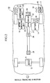
- numeral 10 denotes a hybrid vehicle, equipped with a drive unit 12 in the front part of the vehicle body, having a motor housed therein for driving front wheels, and an engine 13 in an engine compartment in the rear part of the vehicle body, for driving rear wheels.
- the hybrid vehicle 10 runs as a front-wheel-drive vehicle at the time of low speed driving, using the motor 11 as a drive source, and runs as a rear-wheel-drive vehicle at the time of high speed driving exceeding a certain speed, by switching the drive source to the engine 13. Since the motor 11 is provided in the front part of the vehicle body, the engine 13 is arranged in the rear part of the vehicle body, in consideration of the freedom of installation space and reduction in air resistance (Cd value).
- numeral 14 denotes a battery which is a power source for the motor 11
- numeral 15 denotes a motor generator unit for converting the driving force of the engine 13 into electrical power and storing the electrical power in the battery 14.
- An electrical power generation motor (not shown) is mounted in the motor generator unit 15, and electrical power is generated by transmitting the driving force from the engine 13 to the electrical power generation motor.
- the motor generator unit 15 has a function to convert electrical power stored in the battery 14 into the driving force, by driving the electrical power generation motor with the electrical power.
- Numeral 50 denotes an I/C (inter-cooler) EGR system provided in the engine 13.
- Numeral 16 denotes a radiator for cooling the engine 13
- 17 denotes a radiator for power elements, provided together with the radiator 16 for cooling the engine 13.
- the radiator 16 for the power elements is for cooling the driving motor 11, and the motor generator unit 15.
- the radiator 16 for cooling the engine and the radiator 17 for the power elements are equipped with a radiator cooling fan 18 which passes outside air drawn in from the side face of the vehicle body through the radiators for cooling and thereby releases heat to the air in the inner periphery of the engine room.
- a battery heat exchanger 19 for transferring heat from the engine 13 to the battery 14.
- numeral 20 denotes a compressor unit with a variable refrigerant supply capacity
- 21 denotes an outdoor heat exchanger
- 22 denotes a fan for drawing in outside air
- 23 denotes an air conditioning unit referred to as an HPVM (Heat Pump Ventilating Module) which incorporates equipment such as a blower fan 24 provided as a distribution fan, an indoor heat exchanger 25 and a heater core 26 serving as a heating heat exchanger, arranged sequentially in the flow direction inside a casing 23a serving as a flow path for intake air.
- HPVM Heat Pump Ventilating Module
- the outdoor heat exchanger 21 is arranged on the right side face in the engine room disposed in the rear part of the vehicle body, for forcibly exchanging heat between outside air drawn in from an opening on the side face of the vehicle body by operation of the fan 22 for drawing in outside air, and refrigerant flowing inside the heat exchanger.
- the air conditioning unit 23 is arranged in the middle of the rear part of the vehicle body, with a front face of the unit 21 connected to a duct 27 extending to the front of the vehicle body along a center of a lower part of the vehicle body.
- the duct 27 is formed in a tubular shape and is provided with air outlet sections 28 and 29 in the central portion and in the front end of the duct 27, respectively. In this case, the air outlet section 28 is for the rear seats, and the air outlet section 29 is for the front seats, but these may increased or decreased according to need.
- the air conditioning unit 23 is a module for executing cooling, heating and dehumidifying to effect air conditioning, by making outside air drawn in from outside the vehicle body or inside air drawn in from the vehicle cabin with the operation of the blower fan 24, pass through the indoor heat exchanger 25 and the heater core 26.
- the indoor heat exchanger 25 is connected by a refrigerant path 30 to the compressor unit 20 and the outdoor heat exchanger 21 to constitute the air conditioner using a heat pump.
- the compressor unit 20 comprises a variable capacity compressor 31, an accumulator 32, a four way valve 33 and a throttling resistance 34 such as an expansion valve, and operates the variable capacity compressor 31 to circulate the refrigerant which is quantity controlled according to air conditioning load, to thereby execute the heat pump operation.
- temperature adjustment of the discharge air is effected by controlling the refrigerant supply quantity with the variable capacity compressor 31.
- the damper 36 is attached to the upper wall interior of the casing 23a with a hinge 36a so as to be able to swing relative thereto.
- the intake air drawn into the damper 36 is branched into two, and flows through the air flow path 35 and the path through the heater core 26.
- the air flow path on the heater core 26 side has a substantial pressure loss compared to the air flow path 35 side, and hence the intake air actually flowing through the heater core 26 is a reduced quantity. Consequently, the overall flow path area is greater compared to when the heater core 26 is covered by a damper or the like, and hence the pressure loss is reduced by that amount.
- the heater core 26 is connected to the engine cooling water system 37 of the engine 13 and is supplied by high temperature engine cooling water, and thus has a heating function for heating the passing intake air.
- the engine cooling water system 37 of the engine 13 is a circuit in which engine cooling water which is circulated inside the engine by means of a pump (not shown in the figure) which is operated by taking part of the output from the engine 13 as a drive force, and thus becomes a high temperature, is sent to the radiator 16 and cooled by dissipating heat to the outside air.
- thermostat valve remains closed until the engine cooling water becomes a high temperature above a predetermined value, thus preventing circulation to the radiator 16 so that the engine cooling water is warmed up in a short time.
- the normal heating operation employs a mode where the damper 36 is fully closed and the engine cooling water flows in the heater core 26.
- the inside air or outside air (referred to hereunder as the intake air) drawn into the casing 23a by operation of the blower fan 24 passes through the indoor heat exchanger 25 and then passes through the heater core 26 to be heated by the heat of the engine cooling water.
- warmed up intake air is introduced to the duct 27 and discharged from the respective discharge sections 28, 29.
- heating of the vehicle cabin can be effected using this intake air. Under travelling conditions with the engine 13 driving, if there is a normal heating load, then this can be adequately met with such a heating operation.
- dehumidified intake air which has passed through the indoor heat exchanger 25 can also be heated to give heating.
- the level for the heating requirement can be judged for example by detecting the discharge temperature.
- the variable capacity compressor 31 draws in and compresses the low-temperature and low-pressure gas refrigerant and outputs an amount of refrigerant corresponding to the cooling load to the four way valve 33 as a high-temperature and high-pressure gas refrigerant.
- the four way valve 33 is so set as to send the refrigerant to the indoor heat exchanger 25, the high-temperature and high-pressure gas refrigerant is sent to the indoor heat exchanger 25 through the refrigerant path 30, and heat is exchanged with the intake air drawn in by the blower fan 24 to warm the air.
- the heat of the high-temperature and high-pressure gas refrigerant is absorbed by the intake air, and the high-temperature and high-pressure gas refrigerant is changed to a condensate and becomes a high-temperature and high-pressure liquid refrigerant.
- the intake air passing through the indoor heat exchanger 25 is heated by this heat and supplied to the vehicle cabin as warm air.
- the indoor heat exchanger 25 in this case functions as a condenser.
- the refrigerant exiting from the indoor heat exchanger 25 as the high-temperature and high-pressure liquid refrigerant is decompressed and expanded by the throttling resistance 34 in the compressor unit 20 to become a low-temperature and low-pressure liquid refrigerant, and is then sent to the outdoor heat exchanger 21 installed along the side face of the vehicle body.
- Outside air drawn in by the fan 22 for drawing in outside air passes through the outdoor heat exchanger 21, and the outdoor heat exchanger 21 exchanges heat with outside air to draw up the heat. Therefore, the low-temperature and low-pressure liquid refrigerant is warmed by the outside air which has a relatively higher temperature, and is evaporated and gasified to become a low-temperature and low-pressure gas refrigerant.
- the outdoor heat exchanger 21 in this case functions as an evaporator.
- the refrigerant which has become the low-temperature and low-pressure gas is then sent to the four way valve 33 and directed to the accumulator 33 where the liquid component is removed, after which the gas is again drawn into the compressor 21 and compressed.
- the same refrigeration cycle is repeated to effect heating of the vehicle cabin.
- the intake air which has passed through the indoor heat exchanger 25 to become warm air passes in full through the heater core 26 since the damper 36 is fully closed, and is reheated. Consequently, compared to heating with the heater core 26 alone, this is heated in two stages by the indoor heat exchanger 25 and the heater core 26. Hence the amount of heat heating the intake air is increased. Moreover, the heating due to the heater core 26 is performed.on high temperature intake air. Therefore, the heating performance is increased so that when initiating the heating operation, the temperature can be raised quickly. Moreover, even in the case where the temperature of the intake air is low, the warmed warm air can be discharged until the desired temperature is reached to enable heating.
- the discharge temperature can be easily controlled. That is, with the damper 36 fully closed, conditions on the flow path side do not change. Hence if the heating conditions of the indoor heat exchanger 25 and the heater core 26 are constant, then by increasing the quantity of intake air, the discharge temperature is decreased while conversely by decreasing the air quantity, the discharge temperature is increased.
- the heating operation is substantially performed only by the air conditioner using a heat pump.
- the damper 36 is opened fully, so that heating is mainly by the warm air passing through the air flow path 35.
- the heating operation by means of the air conditioner using a heat pump continues until the engine cooling water temperature supplied to the heater core 26 goes above a predetermined value. Since with the operation with the damper 36 fully opened, there is a flow of warm air passing through the air flow path 35 and the heater core 26, the area of the flow path is large so that the resistance value is low. Consequently, the pressure loss is reduced, and the load on the blower fan 24 is also reduced. Moreover, the flow of intake air (warm air) becomes a uniform flow being approximately a straight flow. Hence from this point also the load on the blower fan 24 is reduced, and hence the noise accompanying the air conditioning operation can be reduced.
- the engine cooling water inside the heater core 26 can be heated.
- the temperature of the engine cooling water which reduces the discharge temperature can be raised to a predetermined value quickly so that the heating operation with the abovementioned two stage heating can be executed in a short time.
- the damper 36 at this time is in the fully open position, and the flow of the refrigerant is in the counterclockwise direction in FIG. 1 (shown by the broken line arrow).
- the variable capacity compressor 31 draws in and compresses the low-temperature and low-pressure gas refrigerant, and outputs refrigerant with the supply quantity changed corresponding to cooling load, to the four way valve 33 as a high-temperature and high-pressure gas refrigerant.
- the four way valve 33 is so set as to send the refrigerant to the outdoor heat exchanger 21, the high-temperature and high-pressure gas refrigerant is sent to the outdoor heat exchanger 21 through the refrigerant path 30, and heat is exchanged with outside air drawn in by the fan 22 for drawing in outside air.
- the heat of the high-temperature and high-pressure gas refrigerant is absorbed by the outside air which has a relatively lower temperature, and the high-temperature and high-pressure gas refrigerant is changed to a condensate and becomes a high-temperature and high-pressure liquid refrigerant.
- the outdoor heat exchanger 21 in this case functions as a condenser.
- the high-temperature and high-pressure liquid refrigerant is sent to the throttling resistance 34, and decompressed and expanded in passing through the throttling resistance 34 to become a low-temperature and low-pressure liquid refrigerant.
- the low-temperature and low-pressure liquid refrigerant is then sent to the indoor heat exchanger 25 and exchanges heat with the intake air drawn in by the blower fan 24, and absorbs heat from the intake air to effect cooling.
- the low-temperature and low-pressure liquid refrigerant is evaporated and gasified to become a low-temperature and low-pressure gas refrigerant.
- the intake air becomes cool air and passes through the air flow path 35 and the heater core 26 to be supplied to the vehicle cabin.
- the indoor heat exchanger 25 in this case functions as an evaporator.
- the low-temperature and low-pressure gas refrigerant exiting from the indoor heat exchanger 25 is sent to the accumulator 32 through the four way valve 33, and the liquid component in the refrigerant is removed.
- the low-temperature low-pressure gas refrigerant is then again drawn into the compressor 31 from the accumulator 32 and compressed, after which the same refrigeration cycle is repeated to effect cooling of the vehicle cabin.
- a bypass valve 38 is provided in the engine cooling system 37, so as to be able to form a bypass flow path which bypasses the heater core 26.
- the bypass valve 38 is connected between a primary side flow path 37a which introduces engine cooling water to the heater core 26 from the engine 13, and a secondary side flow path 37b which returns the engine cooling water to the engine 13 from the heater core 26, so as to be able to selectively form a bypass flow path which returns to the engine 13 without passing through the heater core 26.
- bypass valve 38 by opening and closing the bypass valve 38, then one or other of a normal engine cooling water flow path from the engine 13 passing through the heater core 26 and returning to the engine 13, or an engine cooling water bypass flow path from the engine 13 returning to the engine 13 via the bypass valve 38 can be selected.
- bypass valve 38 for example a fully closed/fully open type such as a solenoid valve may be used.
- a flow control valve which can control the flow quantity of engine cooling water such as with a butterfly valve is preferable.
- the flow quantity of engine cooling water bypassing the heater core 26 can be appropriately adjusted within a range from 0 ⁇ 100%. Therefore, the intake air which has been cooled by the indoor heat exchanger 25 or the intake air which has simply passed through the indoor heat exchanger 25 can be appropriately heated by the heater core 26, enabling the discharge temperature to be adjusted. That is, this can be set so that if the flow quantity of the engine cooling water flowing to the heater core 26 is increased, the heating amount is increased with this increase so that the discharge temperature is increased. Conversely, if the flow quantity of engine cooling water flowing to the heater core 26 is reduced, the discharge temperature is reduced.
- this embodiment in addition to the single application, this may be combined with the abovementioned first embodiment.
- this embodiment since in order to reduce the pressure loss, the heater core 26 is made an intake air flow path in addition to the air flow path 35, this embodiment can prevent the reduction in the cooling capacity due to heating of the cold air which has been expressly been cooled by the indoor heat exchanger 25.
- a cooling water pump 39 is provided in the engine cooling water system 37.
- the cooling water pump 39 has an electric motor (not shown in the figure) operated for example by a battery 14, as a drive source.
- the power supply to the electric motor is stopped.
- the power supply to the electric motor is started as required to operate the cooling water pump 39 so that engine cooling water is circulated to the heater core 26 by the cooling water pump 39.
- a normal pump housed in the engine is operated to circulate the engine cooling water.
- high temperature engine cooling water can be supplied to the heater core 26 even after the engine 13 has stopped, and used in the heating operation. That is, in the case of the abovementioned hybrid vehicle, since normally high speed travelling is performed with the engine 13, then after engine travelling has continued for more than a certain amount, the engine cooling water will remain at a high temperature for quite a while even after switching to the motor travelling mode.
- the heating capacity of the vehicular air conditioner can improve the time limit due to the engine cooling water being at a low temperature.
- the third embodiment also can be suitably combined with the above mentioned first embodiment and second embodiment and executed.
- variable capacity compressor has been used in the air conditioner using a heat pump.
- constant volume compressor and effect operation by on/off control with a clutch.
- the vehicle in which the vehicular air conditioner is installed is a hybrid vehicle.
- this may be applicable to a vehicle having an internal combustion engine as with conventional vehicles.
Claims (6)
- Climatiseur de véhicule comprenant une pompe à chaleur, avec une unité de compresseur (20) équipée d'un compresseur (31), d'une résistance d'étranglement (34) et d'une vanne à quatre voies (33), reliée par un trajet de fluide frigorigène à un échangeur de chaleur intérieur (25) pour effectuer un échange de chaleur entre un fluide frigorigène et de l'air d'admission et à un échangeur de chaleur extérieur (21) pour effectuer un échange de chaleur entre un fluide frigorigène et de l'air extérieur, qui exécute une opération de refroidissement et une opération de chauffage en commutant une direction de l'écoulement dudit fluide frigorigène, pourvu d'un ventilateur de distribution d'air, et d'un échangeur de chaleur de chauffage (26) relié à un système d'eau de refroidissement de moteur (37), dans lequel il est prévu une unité de conditionnement d'air (23) avec ledit échangeur de chaleur intérieur et ledit échangeur de chaleur de chauffage agencés en série à partir d'un côté amont dans un boîtier (23a) qui sert de trajet d'écoulement pour ledit air d'admission, et un trajet d'écoulement d'air (35) formé dans une partie au-dessus dudit échangeur de chaleur de chauffage et pourvu de moyens d'ouverture/fermeture (36) pour commuter le trajet d'écoulement d'air entre l'une ou l'autre d'une condition de fermeture complète et d'une condition d'ouverture complète, les moyens d'ouverture/fermeture étant agencés de sorte qu'ils ne ferment pas l'échangeur de chaleur de chauffage dans les deux conditions, caractérisé en ce que
ledit trajet d'écoulement d'air (35) formé au-dessus dudit échangeur de chaleur de chauffage contourne ledit échangeur de chaleur de chauffage et ledit trajet d'écoulement pour ledit air d'amission suit un écoulement droit par rapport au trajet d'écoulement d'air (35) de dérivation. - Climatiseur de véhicule selon la revendication 1, dans lequel ledit échangeur de chaleur de chauffage est installé verticalement à travers le passage d'écoulement défini par ledit boîtier.
- Climatiseur de véhicule selon l'une ou l'autre de la revendication 1 et de la revendication 2, dans lequel ledit compresseur est d'un type à capacité variable.
- Système de climatiseur de véhicule comprenant un climatiseur de véhicule selon la revendication 1, dans lequel une vanne de dérivation (38) est prévue dans ledit système d'eau de refroidissement de moteur (37), de manière à être capable de former un trajet d'écoulement de dérivation d'eau de refroidissement de moteur qui contourne ledit échangeur de chaleur de chauffage.
- Système de climatiseur de véhicule selon la revendication 4, dans lequel ladite vanne de dérivation est une vanne de régulation de débit.
- Système de climatiseur de véhicule comprenant un climatiseur de véhicule selon la revendication 1, dans lequel une pompe à eau de refroidissement (39) est prévue dans ledit système d'eau de refroidissement de moteur pour fonctionner lorsque le moteur est arrêté.
Applications Claiming Priority (2)
| Application Number | Priority Date | Filing Date | Title |
|---|---|---|---|
| US326609 | 1994-10-20 | ||
| US09/326,609 US20030182955A1 (en) | 1999-06-07 | 1999-06-07 | Vehicular air conditioner |
Publications (3)
| Publication Number | Publication Date |
|---|---|
| EP1059182A2 EP1059182A2 (fr) | 2000-12-13 |
| EP1059182A3 EP1059182A3 (fr) | 2003-01-29 |
| EP1059182B1 true EP1059182B1 (fr) | 2006-05-24 |
Family
ID=23272946
Family Applications (1)
| Application Number | Title | Priority Date | Filing Date |
|---|---|---|---|
| EP00401587A Expired - Lifetime EP1059182B1 (fr) | 1999-06-07 | 2000-06-06 | Appareil de climatisation pour véhicules |
Country Status (6)
| Country | Link |
|---|---|
| US (2) | US20030182955A1 (fr) |
| EP (1) | EP1059182B1 (fr) |
| JP (1) | JP2001001749A (fr) |
| KR (1) | KR100392622B1 (fr) |
| CN (1) | CN1147401C (fr) |
| DE (1) | DE60028129T2 (fr) |
Cited By (1)
| Publication number | Priority date | Publication date | Assignee | Title |
|---|---|---|---|---|
| WO2015139662A1 (fr) * | 2014-03-21 | 2015-09-24 | 台湾立凯绿能移动股份有限公司 | Système de circulation pour autobus électrique à autonomie étendue |
Families Citing this family (49)
| Publication number | Priority date | Publication date | Assignee | Title |
|---|---|---|---|---|
| US6233957B1 (en) * | 1999-06-07 | 2001-05-22 | Mitsubishi Heavy Industries, Ltd. | Vehicular air conditioner |
| JP2002240537A (ja) * | 2001-02-13 | 2002-08-28 | Sanyo Electric Co Ltd | 自動車用空調システム及びその運転方法 |
| WO2003074305A2 (fr) * | 2002-03-04 | 2003-09-12 | Luk Fahrzeug-Hydraulik Gmbh & Co. Kg | Installation de climatisation |
| JP2004142551A (ja) * | 2002-10-23 | 2004-05-20 | Sanden Corp | 車両用空調装置 |
| DE102004026478A1 (de) * | 2003-06-04 | 2005-03-10 | Behr Gmbh & Co Kg | Verfahren zur Regelung einer Klimaanlage, insbesondere eines Kraftfahrzeugs |
| DE10346827B4 (de) * | 2003-10-06 | 2017-07-13 | Mahle International Gmbh | Verfahren zur Regelung der Lufttemperatur einer Kfz-Klimaanlage mit Zuheizfunktion |
| CA2573082A1 (fr) * | 2004-07-09 | 2006-01-19 | Junjie Gu | Systeme de refrigeration |
| KR100550573B1 (ko) * | 2004-08-17 | 2006-02-10 | 엘지전자 주식회사 | 코제너레이션 시스템 |
| KR100591337B1 (ko) * | 2004-08-17 | 2006-06-19 | 엘지전자 주식회사 | 코제너레이션 시스템 |
| KR100624815B1 (ko) * | 2004-08-17 | 2006-09-20 | 엘지전자 주식회사 | 코제너레이션 시스템의 배기가스 열교환기 |
| US20080041046A1 (en) * | 2006-08-16 | 2008-02-21 | Deere & Company, A Delaware Corporation | Engine waste heat recovery system |
| KR100831450B1 (ko) * | 2006-09-11 | 2008-05-21 | 현대자동차주식회사 | 히터 블로워를 이용한 엔진룸 냉각 시스템 및 방법 |
| JP4836201B2 (ja) * | 2007-07-26 | 2011-12-14 | 東京瓦斯株式会社 | 厨房システム |
| US8272432B2 (en) * | 2007-11-28 | 2012-09-25 | GM Global Technology Operations LLC | HVAC thermal storage for hybrid vehicle |
| KR101401994B1 (ko) * | 2007-11-30 | 2014-06-27 | 한라비스테온공조 주식회사 | 자동차용 히트 펌프 시스템 |
| DE102009039181B4 (de) | 2009-08-28 | 2023-10-05 | Still Gesellschaft Mit Beschränkter Haftung | Klimatisierungsvorrichtung für ein Elektrofahrzeug |
| JP5494312B2 (ja) * | 2009-09-03 | 2014-05-14 | 株式会社デンソー | 車両用空調装置 |
| JP5433387B2 (ja) * | 2009-11-30 | 2014-03-05 | 株式会社日立製作所 | 車両用機器冷却暖房システム |
| EP2407328B1 (fr) * | 2010-07-16 | 2012-10-17 | Eberspächer catem GmbH & Co. KG | Dispositif de chauffage électrique |
| CN102374604B (zh) * | 2010-08-18 | 2014-04-16 | 上海汽车集团股份有限公司 | 车辆空调温度控制的方法及系统 |
| CN103238035A (zh) * | 2010-09-27 | 2013-08-07 | 特米亚热力有限公司 | 热交换器装置和热泵系统 |
| KR101189417B1 (ko) * | 2010-11-30 | 2012-10-15 | 기아자동차주식회사 | 차량의 온도 조절장치 |
| JP5316819B2 (ja) * | 2010-12-13 | 2013-10-16 | 三菱自動車工業株式会社 | 車両用暖房装置 |
| DE102011010282A1 (de) * | 2011-02-03 | 2012-08-09 | Still Gmbh | Klimatisierungsvorrichtung für ein Elektrofahrzeug |
| US8806882B2 (en) * | 2011-02-25 | 2014-08-19 | Alliance for Substainable Energy, LLC | Parallel integrated thermal management |
| CN102654323B (zh) * | 2011-03-03 | 2015-01-21 | 山东朗进科技股份有限公司 | 汽车空调系统及六通阀 |
| US9072189B2 (en) * | 2011-03-16 | 2015-06-30 | Toyota Jidosha Kabushiki Kaisha | Substrate unit |
| JP5370402B2 (ja) | 2011-03-28 | 2013-12-18 | 株式会社デンソー | 車両用空調装置 |
| JP5659925B2 (ja) | 2011-04-04 | 2015-01-28 | 株式会社デンソー | 車両用空調装置 |
| JP5815284B2 (ja) * | 2011-05-20 | 2015-11-17 | 株式会社日本自動車部品総合研究所 | 冷却装置 |
| KR101339226B1 (ko) * | 2011-06-20 | 2013-12-09 | 기아자동차 주식회사 | 차량용 히트펌프 시스템 및 그 제어방법 |
| JP5492861B2 (ja) * | 2011-11-01 | 2014-05-14 | 富士重工業株式会社 | 車両、空調装置、および空調方法 |
| JP2013159228A (ja) * | 2012-02-06 | 2013-08-19 | Denso Corp | 車両用空調装置 |
| EP2634021B1 (fr) * | 2012-03-02 | 2015-04-08 | Halla Visteon Climate Control Corp. | Système de pompe à chaleur pour véhicule et procédé de commande de celui-ci |
| DE102012107712A1 (de) * | 2012-08-22 | 2014-02-27 | Aht Cooling Systems Gmbh | Kühlregal |
| CN104422024B (zh) * | 2013-09-05 | 2019-03-12 | 杭州三花研究院有限公司 | 汽车空调系统及其控制方法 |
| CN104442273A (zh) * | 2013-09-17 | 2015-03-25 | 北汽福田汽车股份有限公司 | 用于汽车的空调系统及其控制方法 |
| TWI602719B (zh) * | 2013-10-23 | 2017-10-21 | Air-conditioning system with air intake bypass | |
| FR3029848B1 (fr) * | 2014-12-10 | 2018-04-27 | Valeo Systemes Thermiques | Dispositif de climatisation pour vehicule automobile |
| JP6590558B2 (ja) | 2015-07-01 | 2019-10-16 | サンデン・オートモーティブクライメイトシステム株式会社 | 車両用空気調和装置 |
| JP6292211B2 (ja) * | 2015-11-20 | 2018-03-14 | トヨタ自動車株式会社 | 車両用吸着式空調装置 |
| CN105691146A (zh) * | 2016-01-14 | 2016-06-22 | 南京航空航天大学 | 车辆空调系统及其工作方法 |
| FR3052236B1 (fr) * | 2016-06-07 | 2019-05-10 | Valeo Systemes Thermiques | Circuit de climatisation de vehicule automobile |
| JP6642857B2 (ja) * | 2016-10-18 | 2020-02-12 | 本田技研工業株式会社 | 車両用空調装置 |
| JP2018203063A (ja) * | 2017-06-05 | 2018-12-27 | サンデン・オートモーティブクライメイトシステム株式会社 | 車両用空気調和装置 |
| KR102382724B1 (ko) * | 2017-09-27 | 2022-04-05 | 한온시스템 주식회사 | 차량용 공조장치 |
| JP7024537B2 (ja) * | 2018-03-22 | 2022-02-24 | 株式会社デンソー | 冷却装置 |
| CN108674125A (zh) * | 2018-04-27 | 2018-10-19 | 奇瑞汽车股份有限公司 | 一种车用空调系统及其控制方法 |
| KR20200040996A (ko) * | 2018-10-11 | 2020-04-21 | 현대자동차주식회사 | 차량의 공조 시스템 |
Family Cites Families (18)
| Publication number | Priority date | Publication date | Assignee | Title |
|---|---|---|---|---|
| US4373666A (en) * | 1981-06-26 | 1983-02-15 | General Motors Corporation | Engine cooling-passenger heating system |
| JPS58110317A (ja) * | 1981-12-23 | 1983-06-30 | Mitsubishi Heavy Ind Ltd | 車輌用空調装置 |
| US4454984A (en) * | 1982-11-01 | 1984-06-19 | Evans Products Company | Auxiliary circulation system for vehicle heaters |
| DE3606591A1 (de) * | 1986-02-28 | 1987-09-10 | Bayerische Motoren Werke Ag | Heiz- und kuehlvorrichtung fuer kraftfahrzeuge |
| JPH0784865B2 (ja) * | 1986-12-16 | 1995-09-13 | カルソニック株式会社 | 容量可変斜板式コンプレツサの制御装置 |
| US4842047A (en) * | 1988-06-03 | 1989-06-27 | Diesel Kiki Co., Ltd. | Air conditioner for automobiles |
| US4905893A (en) * | 1988-12-22 | 1990-03-06 | Kiskis James M | Reserve automobile heating system |
| US5316074A (en) * | 1990-10-12 | 1994-05-31 | Nippondenso Co., Ltd. | Automotive hair conditioner |
| JP2531043B2 (ja) * | 1991-03-26 | 1996-09-04 | 日本電装株式会社 | 車両用空調装置 |
| US5605051A (en) * | 1991-04-26 | 1997-02-25 | Nippondenso Co., Ltd. | Automotive air conditioner having condenser and evaporator provided within air duct |
| JP3119281B2 (ja) * | 1991-10-14 | 2000-12-18 | 株式会社デンソー | 車両用空調装置 |
| US5309731A (en) * | 1991-12-27 | 1994-05-10 | Nippondenso Co., Ltd. | Air conditioning apparatus |
| JPH05213049A (ja) * | 1992-02-07 | 1993-08-24 | Zexel Corp | ヒートポンプ式空調装置の操作装置 |
| US5526650A (en) * | 1993-09-21 | 1996-06-18 | Nippondenso Co., Ltd. | Air-conditioning apparatus |
| JPH10100652A (ja) * | 1996-10-02 | 1998-04-21 | Matsushita Electric Ind Co Ltd | 自動車用空調制御装置 |
| JP3333689B2 (ja) * | 1996-10-09 | 2002-10-15 | 松下電器産業株式会社 | 自動車用空調制御装置 |
| JP3952545B2 (ja) * | 1997-07-24 | 2007-08-01 | 株式会社デンソー | 車両用空調装置 |
| US6237357B1 (en) * | 1999-06-07 | 2001-05-29 | Mitsubishi Heavy Industries, Ltd. | Vehicular air conditioner using heat pump |
-
1999
- 1999-06-07 US US09/326,609 patent/US20030182955A1/en not_active Abandoned
-
2000
- 2000-06-06 EP EP00401587A patent/EP1059182B1/fr not_active Expired - Lifetime
- 2000-06-06 DE DE60028129T patent/DE60028129T2/de not_active Expired - Fee Related
- 2000-06-07 KR KR10-2000-0031172A patent/KR100392622B1/ko not_active IP Right Cessation
- 2000-06-07 JP JP2000171272A patent/JP2001001749A/ja active Pending
- 2000-06-07 CN CNB001203010A patent/CN1147401C/zh not_active Expired - Fee Related
-
2003
- 2003-08-21 US US10/644,728 patent/US20050257547A1/en not_active Abandoned
Cited By (1)
| Publication number | Priority date | Publication date | Assignee | Title |
|---|---|---|---|---|
| WO2015139662A1 (fr) * | 2014-03-21 | 2015-09-24 | 台湾立凯绿能移动股份有限公司 | Système de circulation pour autobus électrique à autonomie étendue |
Also Published As
| Publication number | Publication date |
|---|---|
| CN1288828A (zh) | 2001-03-28 |
| US20030182955A1 (en) | 2003-10-02 |
| US20050257547A1 (en) | 2005-11-24 |
| DE60028129D1 (de) | 2006-06-29 |
| DE60028129T2 (de) | 2006-12-21 |
| KR100392622B1 (ko) | 2003-07-28 |
| JP2001001749A (ja) | 2001-01-09 |
| CN1147401C (zh) | 2004-04-28 |
| KR20010007281A (ko) | 2001-01-26 |
| EP1059182A3 (fr) | 2003-01-29 |
| EP1059182A2 (fr) | 2000-12-13 |
Similar Documents
| Publication | Publication Date | Title |
|---|---|---|
| EP1059182B1 (fr) | Appareil de climatisation pour véhicules | |
| US6237357B1 (en) | Vehicular air conditioner using heat pump | |
| CN109291763B (zh) | 一种热泵空调系统及其控制方法和汽车 | |
| EP2497662B1 (fr) | Système avec pompe à chaleur pour véhicule | |
| JP3119281B2 (ja) | 車両用空調装置 | |
| KR100359700B1 (ko) | 차량용 엔진 냉각장치 | |
| CN109291761B (zh) | 一种电动汽车热泵空调系统 | |
| JP3736847B2 (ja) | 空調装置及び空調方法 | |
| CN115427240A (zh) | 汽车用热泵系统 | |
| US20100293966A1 (en) | Vehicle air conditioner | |
| CN111615464A (zh) | 车用空调装置 | |
| JP2008308080A (ja) | 自動車の吸放熱システムおよびその制御方法 | |
| CN102059930B (zh) | 热回收汽车空调 | |
| CN111591100A (zh) | 一种车辆、车辆的空调系统及其控制方法 | |
| JP2004042759A (ja) | 自動車用空気調和機 | |
| JP2004182109A (ja) | 車両用空調装置 | |
| US20230158858A1 (en) | Method for Controlling Vehicle HVAC System | |
| CN112543855B (zh) | 复合阀及使用该复合阀的车用空调装置 | |
| CN213322561U (zh) | 一种车辆及车辆的空调系统 | |
| JP3321871B2 (ja) | 車両用ヒートポンプ式空調装置 | |
| KR20220122391A (ko) | 차량용 열관리시스템의 난방 제어방법 | |
| JP3275321B2 (ja) | 自動車用空気調和装置 | |
| CN111780465A (zh) | 无需停机的电动汽车热泵除霜系统及其运行方法 | |
| KR100188061B1 (ko) | 자동차용 냉 난방겸용 공기조화기 | |
| KR102577144B1 (ko) | 자동차용 히트펌프 시스템 |
Legal Events
| Date | Code | Title | Description |
|---|---|---|---|
| PUAI | Public reference made under article 153(3) epc to a published international application that has entered the european phase |
Free format text: ORIGINAL CODE: 0009012 |
|
| 17P | Request for examination filed |
Effective date: 20000617 |
|
| AK | Designated contracting states |
Kind code of ref document: A2 Designated state(s): AT BE CH CY DE DK ES FI FR GB GR IE IT LI LU MC NL PT SE |
|
| AX | Request for extension of the european patent |
Free format text: AL;LT;LV;MK;RO;SI |
|
| PUAL | Search report despatched |
Free format text: ORIGINAL CODE: 0009013 |
|
| AK | Designated contracting states |
Designated state(s): AT BE CH CY DE DK ES FI FR GB GR IE IT LI LU MC NL PT SE |
|
| AX | Request for extension of the european patent |
Extension state: AL LT LV MK RO SI |
|
| 17Q | First examination report despatched |
Effective date: 20030620 |
|
| AKX | Designation fees paid |
Designated state(s): DE FR GB IT |
|
| GRAP | Despatch of communication of intention to grant a patent |
Free format text: ORIGINAL CODE: EPIDOSNIGR1 |
|
| RIN1 | Information on inventor provided before grant (corrected) |
Inventor name: NIWA, KAZUKI, MITSUBISHI HEAVY INDUSTRIES LTD Inventor name: HIRAO, TOYOTAKA MITSUBISHI HEAVY INDUSTRIES LTD Inventor name: MAJOR, GREGORY A. Inventor name: AKIMOTO, RYOSAKU, MITSUBISHI HEAVY INDUSTRIES LTD Inventor name: ZENG, XIN |
|
| RAP1 | Party data changed (applicant data changed or rights of an application transferred) |
Owner name: MITSUBISHI HEAVY INDUSTRIES, LTD. Owner name: GENERAL MOTORS CORPORATION |
|
| GRAS | Grant fee paid |
Free format text: ORIGINAL CODE: EPIDOSNIGR3 |
|
| GRAA | (expected) grant |
Free format text: ORIGINAL CODE: 0009210 |
|
| AK | Designated contracting states |
Kind code of ref document: B1 Designated state(s): DE FR GB IT |
|
| PG25 | Lapsed in a contracting state [announced via postgrant information from national office to epo] |
Ref country code: IT Free format text: LAPSE BECAUSE OF FAILURE TO SUBMIT A TRANSLATION OF THE DESCRIPTION OR TO PAY THE FEE WITHIN THE PRESCRIBED TIME-LIMIT;WARNING: LAPSES OF ITALIAN PATENTS WITH EFFECTIVE DATE BEFORE 2007 MAY HAVE OCCURRED AT ANY TIME BEFORE 2007. THE CORRECT EFFECTIVE DATE MAY BE DIFFERENT FROM THE ONE RECORDED. Effective date: 20060524 |
|
| REG | Reference to a national code |
Ref country code: GB Ref legal event code: FG4D |
|
| RIN1 | Information on inventor provided before grant (corrected) |
Inventor name: ZENG, XIN Inventor name: HIRAO, TOYOTAKA MITSUBISHI HEAVY INDUSTRIES LTD Inventor name: MAJOR, GREGORY A. Inventor name: NIWA, KAZUKI,MITSUBISHI HEAVY INDUSTRIES LTD Inventor name: AKIMOTO, RYOSAKU,MITSUBISHI HEAVY INDUSTRIES LTD |
|
| REF | Corresponds to: |
Ref document number: 60028129 Country of ref document: DE Date of ref document: 20060629 Kind code of ref document: P |
|
| ET | Fr: translation filed | ||
| PLBE | No opposition filed within time limit |
Free format text: ORIGINAL CODE: 0009261 |
|
| STAA | Information on the status of an ep patent application or granted ep patent |
Free format text: STATUS: NO OPPOSITION FILED WITHIN TIME LIMIT |
|
| 26N | No opposition filed |
Effective date: 20070227 |
|
| PGFP | Annual fee paid to national office [announced via postgrant information from national office to epo] |
Ref country code: DE Payment date: 20080612 Year of fee payment: 9 |
|
| PGFP | Annual fee paid to national office [announced via postgrant information from national office to epo] |
Ref country code: FR Payment date: 20080617 Year of fee payment: 9 |
|
| PGFP | Annual fee paid to national office [announced via postgrant information from national office to epo] |
Ref country code: GB Payment date: 20080611 Year of fee payment: 9 |
|
| GBPC | Gb: european patent ceased through non-payment of renewal fee |
Effective date: 20090606 |
|
| REG | Reference to a national code |
Ref country code: FR Ref legal event code: ST Effective date: 20100226 |
|
| PG25 | Lapsed in a contracting state [announced via postgrant information from national office to epo] |
Ref country code: FR Free format text: LAPSE BECAUSE OF NON-PAYMENT OF DUE FEES Effective date: 20090630 |
|
| PG25 | Lapsed in a contracting state [announced via postgrant information from national office to epo] |
Ref country code: GB Free format text: LAPSE BECAUSE OF NON-PAYMENT OF DUE FEES Effective date: 20090606 |
|
| PG25 | Lapsed in a contracting state [announced via postgrant information from national office to epo] |
Ref country code: DE Free format text: LAPSE BECAUSE OF NON-PAYMENT OF DUE FEES Effective date: 20100101 |