EP1058026B1 - Rollbalg-Luftfeder - Google Patents
Rollbalg-Luftfeder Download PDFInfo
- Publication number
- EP1058026B1 EP1058026B1 EP00110758A EP00110758A EP1058026B1 EP 1058026 B1 EP1058026 B1 EP 1058026B1 EP 00110758 A EP00110758 A EP 00110758A EP 00110758 A EP00110758 A EP 00110758A EP 1058026 B1 EP1058026 B1 EP 1058026B1
- Authority
- EP
- European Patent Office
- Prior art keywords
- bellows
- piston
- rolling
- bead
- lobe
- Prior art date
- Legal status (The legal status is an assumption and is not a legal conclusion. Google has not performed a legal analysis and makes no representation as to the accuracy of the status listed.)
- Expired - Lifetime
Links
Images


Classifications
-
- F—MECHANICAL ENGINEERING; LIGHTING; HEATING; WEAPONS; BLASTING
- F16—ENGINEERING ELEMENTS AND UNITS; GENERAL MEASURES FOR PRODUCING AND MAINTAINING EFFECTIVE FUNCTIONING OF MACHINES OR INSTALLATIONS; THERMAL INSULATION IN GENERAL
- F16F—SPRINGS; SHOCK-ABSORBERS; MEANS FOR DAMPING VIBRATION
- F16F9/00—Springs, vibration-dampers, shock-absorbers, or similarly-constructed movement-dampers using a fluid or the equivalent as damping medium
- F16F9/02—Springs, vibration-dampers, shock-absorbers, or similarly-constructed movement-dampers using a fluid or the equivalent as damping medium using gas only or vacuum
- F16F9/04—Springs, vibration-dampers, shock-absorbers, or similarly-constructed movement-dampers using a fluid or the equivalent as damping medium using gas only or vacuum in a chamber with a flexible wall
- F16F9/0454—Springs, vibration-dampers, shock-absorbers, or similarly-constructed movement-dampers using a fluid or the equivalent as damping medium using gas only or vacuum in a chamber with a flexible wall characterised by the assembling method or by the mounting arrangement, e.g. mounting of the membrane
-
- F—MECHANICAL ENGINEERING; LIGHTING; HEATING; WEAPONS; BLASTING
- F16—ENGINEERING ELEMENTS AND UNITS; GENERAL MEASURES FOR PRODUCING AND MAINTAINING EFFECTIVE FUNCTIONING OF MACHINES OR INSTALLATIONS; THERMAL INSULATION IN GENERAL
- F16F—SPRINGS; SHOCK-ABSORBERS; MEANS FOR DAMPING VIBRATION
- F16F9/00—Springs, vibration-dampers, shock-absorbers, or similarly-constructed movement-dampers using a fluid or the equivalent as damping medium
- F16F9/02—Springs, vibration-dampers, shock-absorbers, or similarly-constructed movement-dampers using a fluid or the equivalent as damping medium using gas only or vacuum
- F16F9/04—Springs, vibration-dampers, shock-absorbers, or similarly-constructed movement-dampers using a fluid or the equivalent as damping medium using gas only or vacuum in a chamber with a flexible wall
- F16F9/05—Springs, vibration-dampers, shock-absorbers, or similarly-constructed movement-dampers using a fluid or the equivalent as damping medium using gas only or vacuum in a chamber with a flexible wall the flexible wall being of the rolling diaphragm type
-
- B—PERFORMING OPERATIONS; TRANSPORTING
- B60—VEHICLES IN GENERAL
- B60G—VEHICLE SUSPENSION ARRANGEMENTS
- B60G2206/00—Indexing codes related to the manufacturing of suspensions: constructional features, the materials used, procedures or tools
- B60G2206/01—Constructional features of suspension elements, e.g. arms, dampers, springs
- B60G2206/40—Constructional features of dampers and/or springs
- B60G2206/42—Springs
- B60G2206/424—Plunger or top retainer construction for bellows or rolling lobe type air springs
Definitions
- the invention relates to a bellows air spring according to features 1.1 to 1.3.1. of claim 1 and a process for their manufacture.
- Air springs such as those used in vehicle construction for cushioning wheel suspensions, essentially consist of a rolling bellows (air bellows), which is delimited on the one hand by a cover plate (cone plate) and on the other hand by a rolling piston and thus encloses an air spring volume in its interior.
- the bellows itself is made of rubber or rubber-like plastic with end fastening beads, such as. B. described in DE-OS 29 05 791.
- the roll bellows end located on the cover plate is usually fastened by flanging, which is why the (upper) cover plate is also called “flare plate”.
- the lower edge of the roll bellows ie the lower bead section, is usually designed as a cone provided with sealing grooves, in order then to be screwed to a multi-part rolling piston provided with a tensioning plate.
- EP 0 546 385 B1 is an air bellows with a brace Sealing bead shown by a flanged edge as a crimping plate trained upper fastening part includes and is tightly clamped.
- a bellows air spring which essentially consists of a flexible bellows, a cover plate and a rolling piston.
- the in Fig. 1 air spring shown is composed of these components.
- Such a screw attachment is relatively complex and laborious.
- air springs are known, in which the rolling piston facing end of the rolling bellows is fastened by flanging.
- the lower bead of the air spring bellows is fixed with that of the rolling piston connected.
- the cylindrical rolling piston arranged coaxially with the bellows runs out into a flanged edge which reaches around the bead and against it presses the ring edge of a lid.
- This cover serves to close the guide body close and lock against the bellows.
- the flanged edge is around put the bead of the roller bellows around.
- the piston part consists of a one-piece design Shaped body and is connected to the bellows by flanging that the outer Circumferential wall of the rolling piston for fastening the one facing the rolling piston Bellows is flanged inwards.
- the corresponding bellows has one from Bordered rim encircled bead-like ring approach, with a reinforcing insert is provided.
- An air spring is known from WO 97/21045, which likewise essentially consists of a Cover, a bellows and a rolling piston.
- the bellows shown in FIG. 2 has a corner (26) in its end area, so that there is a partial length at the end, which in the partially turned state of the Bellows is directed inwards. Since the roll bellows bead (32, 33) has a smaller radius has than the rest of the rolling bellows, the geometric shown in Fig. 2 appear Conditions to be realistic. However, the state without is not understandable Roll fold, because the angled section would then point outwards, which is because of the smaller bead radius is practically not possible.
- the following list of requirements has been drawn up to overcome the problems mentioned when fastening the bellows to the open rolling piston by flanging:
- the special design of the bulb-side bead must be such that, during the flanging, the flanged edge comes into contact with the bellows as late as possible in order to prevent the bead from escaping downwards into the free space.
- the crimping gap must already be closed so far when the bead engages that the bead can no longer slip out.
- the bead must immediately clamp against the inner surface of the contact wall when gripping.
- the object of the present invention is, based on the prior art available with the Gbm 298 08 109 U1, to design the piston-end bellows so that it can be securely flanged even when the piston is open at the end. From this prior art, the shape of the bead in the un-flanged state is not known.
- piston side Bead section can be done with a one-piece sheet steel unwinding piston without additional fasteners, such as. B. Clamping plate and the like are crimped. This carries to reduce the number of components in the overall system.
- the bulb-side bulge of the roller bellows is preferably formed at 45 ° to the horizontal ao, that there are no undercuts on the vulcanization mold or on the product itself, there are no molding and molding difficulties.
- the bead is thus so dimensionally stable that a rolling piston can then be flanged with it. Bead formations with sealing surface inclinations between 45 ° and 65 ° have proven to be particularly advantageous. Due to the inward flaring process, the bead swings into a 90 ° position to the horizontal.
- the diameter reduction in the lower area of the bellows is only to favor the formation of the roll fold necessary when operating the air bellows.
- the Diameter of the bead core and the diameter of the Piston wall coordinated.
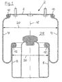
- the bellows air spring 2 shown in FIG. 1 exists essentially from a flexible rubber bellows 4 or rubber-like plastic, a cover plate 6 and a rolling piston 8. At both ends is the Roll bellows 4 each provided with a bead 10, 12.
- the "Upper" bead 10 is by crimping with the cover plate (Flare plate) 6 connected during the bulb-side bead 12 attached to a flanged edge 30 of the rolling piston 8 is.
- cover plate 6 and 8 rolling piston Bellows encloses the air spring interior 28.
- FIG. 2a Essential details of the bellows air spring according to the invention are shown in Figures 2a-c.
- the in Fig. 2a has bellows 4 shown on one side in longitudinal section bulges at both ends.
- the upper bead 10 is formed in a conventional manner and serves to fasten the roller bellows 4 to the cover plate (Flaring plate) 6.
- the lower one, for attachment to the Rolling piston 8 provided roll bellows bead 12 is according to the invention on the flange 30 of the open top Rolling piston 8 adapted.
- the piston shown in Fig. 3 8 shows a cylindrical piston rim 30. This is the condition before beading 12.
- the Geometry of the surface of the bellows and that corresponding production form in relief designed that largely on an undercut can be dispensed with.
- the extensive avoidance of a Undercuts facilitate demolding.
- the bead-shaped thickening of the piston-side roll bellows end has a sealing surface 14.
- the bulb-side bead 12 has a bead core (ring body) 24 made of steel or steel wire.
- the diameter 22 of the bead 12 is matched to the diameter 26 of the piston wall in the piston area.
- the bead 12 of the rolling bellows 4 does not hook into a pre-flanged piston rim 30.
- the piston rim 30 is not pre-flanged.
- the edge 30 is initially cylindrical; it closes only by the flanging process around the bead 12 of the bellows 4.
- the bead 12 is firmly enclosed by the flanged edge 30 of the rolling piston 8, the piston-side sealing surface 14 of the rolling bellows 4 being at 90 °, based on the "horizontal"", is rotated so that it rests over the entire surface of the upper end of the piston wall (Fig. 2c).
- the piston rim 30 is deflected inwards by a total of approximately 270 °. This flanging process is carried out with a special tool.
- the outer surface of the rolling piston 8 is the diameter 22 of the bellows 4 in the bead area less than the other Bellows diameter 20.
- shock absorber is to be integrated in the air spring 2, so it can be a separate part in the open piston 8th to be built in.
Landscapes
- Engineering & Computer Science (AREA)
- General Engineering & Computer Science (AREA)
- Mechanical Engineering (AREA)
- Fluid-Damping Devices (AREA)
- Diaphragms And Bellows (AREA)
- Vehicle Body Suspensions (AREA)
- Moulds For Moulding Plastics Or The Like (AREA)
- Clamps And Clips (AREA)
- Sealing Devices (AREA)
- Glass Compositions (AREA)
- Footwear And Its Accessory, Manufacturing Method And Apparatuses (AREA)
- Joints Allowing Movement (AREA)
Description
Das an der Abdeckplatte befindliche Rollbalg-Ende wird üblicherweise durch Bördeln befestigt, weshalb die (obere) Abdeckplatte auch "Bördelplatte" genannt wird. Der untere Rand des Rollbalgs, d. h. die untere Wulstpartie wird üblicherweise als mit Dichtrillen versehener Konus ausgebildet, um dann - mit einem Spannteller versehen - an einen mehrteiligen Abrollkolben geschraubt zu werden.
Die besondere Ausbildung des kolbenseitigen Wulstes muß derart sein, daß beim Bördeln ein Kontakt der Bördelkante mit dem Balg so spät wie möglich erfolgt, um ein Ausweichen des Wulstes nach unten in den freien Raum zu vermeiden. Der Bördelspalt muß beim Eingreifen des Wulstes bereits so weit geschlossen sein, daß der Wulst nicht mehr herausrutschen kann. Der Wulst muß sich beim Erfassen gleich klemmend gegen die Innenfläche der Kontaktwand legen. Zusammengefaßt besteht die Aufgabe der vorliegenden Erfindung darin, ausgehend von dem mit dem Gbm 298 08 109 U1 vorliegenden Stand der Technik das kolbenseitige Balgende so zu gestalten, daß es auch bei einem stirnseitig offenen Kolben sicher bördelbar ist. Aus diesem Stand der Technik ist die Form des Wulstes im unver bördelten Zustand nicht bekannt.
Wulstausbildungen mit Dichtflächenneigungen zwischen 45° und 65° haben sich als besonders vorteilhaft erwiesen. Durch den einwärts gerichteten Bördelprozeß schwenkt der Wulst in eine 90°-Lage zur Waagerechten.
Zur Verstärkung weist der kolbenseitige Wulst 12 einen Wulstkern (Ringkörper) 24 aus Stahl oder Stahldraht auf.
Dieser Bördelvorgang erfolgt mit einem speziellen Werkzeug.
- 2
- Rollbalg-Luftfeder
- 4
- Rollbalg, Balg
- 6
- Abdeckplatte (Bördelplatte)
- 8
- Abrollkolben
- 10
- oberer Wulst(rand)
- 12
- kolbenseitiger Wulst<rand>
- 14
- kolbenseitige Dichtfläche
- 16
- Balgachse
- 18
- Senkrechte zur Balgachse
- 20
- Rollbalg-Durchmesser
- 22
- Durchmesser des Wulstes im Kolbenbereich
- 24
- Wulstkern (Ringkörper)
- 26
- Durchmesser der Kolbenwand
- 28
- Luftfeder-Innenraum
- 30
- Bördelrand, Bördelkante, Kolbenrand
Claims (6)
- Rollbalg-Luftfeder (2), umfassend:1.1 eine Abdeckplatte (6),1.2 einen Abrollkolben (8) und1.3 einen Rollbalg (4),1.3.1 der an seinem, dem Abrollkolben (8) zugewandten Ende einen mit dem Abrollkolben verbördelten Wulst (12) aufweist,1.3.1.1 der im unverbördelt Zustand derartig ausgebildet ist, dass seine Dichtfläche (14) nicht senkrecht zur Achse (16) des Rollbalgs (4) liegt, sondern - bezogen auf die auf der Balgachse (16) stehenden Senkrechten (18) - unter einem Neigungswinkel α ausgerichtet ist.
- Rollbalg-Luftfeder nach Anspruch 1,
dadurch gekennzeichnet, dass der Winkel α, um den der kolbenseitige Wulst (12) zu der auf der Balgachse (16) stehenden Senkrechten (18) gekippt ist, in einem Winkelbereich von 45° bis 65° liegt. - Rollbalg-Luftfeder nach Anspruch 1 oder 2,
dadurch gekennzeichnet, dass der Rollbalg (4) an seinem dem Abrollkolben (8) zugewandten Ende einen-verglichen mit dem sonstigen Rollbalg-Durchmesser (20) - geringeren Durchmesser (22) aufweist - Rollbalg-Luftfeder nach einem der Ansprüche 1 bis 3,
dadurch gekennzeichnet, dass der Wulst (12) einen starren Wulstkern (24) aufweist, dessen Durchmesser (22) auf den Durchmesser (26) der Kolbenwand abgestimmt ist. - Rollbalg-Luftfeder nach einem der Ansprüche 1 bis 4,
dadurch gekennzeichnet, dass der kolbenseitige Wulst (12) keine Hinterschneidungen - weder seitens der Vulkanisationsform noch am Balg (4) selbst - aufweist. - Verfahren zur Herstellung einer Rollbalg-Luftfeder gemäß einem der Ansprüche 1 bis 5,
dadurch gekennzeichnet, dass zunächst die Dichtfläche (14) des kolbenseitigen Rollbalg-Wulstes (12) gekippt unter einem Winkel α in Richtung der Abdeckplatte zu der auf der Balgachse (16) stehenden Senkrechten (18) formstabil hergestellt wird, und
dass dann der Abrollkolben (8) mit dem so hergestellten Rollbalg (4) in der Weise gebördelt wird,
dass der kolbenseitige Wulst (12) mit seiner Dichtfläche (14) beim abgeschlossenen Bördelvorgang in Richtung der Balgachse (16) zu liegen kommt.
Applications Claiming Priority (2)
| Application Number | Priority Date | Filing Date | Title |
|---|---|---|---|
| DE19925092A DE19925092C2 (de) | 1999-06-01 | 1999-06-01 | Rollbalg-Luftfeder |
| DE19925092 | 1999-06-01 |
Publications (3)
| Publication Number | Publication Date |
|---|---|
| EP1058026A2 EP1058026A2 (de) | 2000-12-06 |
| EP1058026A3 EP1058026A3 (de) | 2003-04-16 |
| EP1058026B1 true EP1058026B1 (de) | 2004-11-17 |
Family
ID=7909885
Family Applications (1)
| Application Number | Title | Priority Date | Filing Date |
|---|---|---|---|
| EP00110758A Expired - Lifetime EP1058026B1 (de) | 1999-06-01 | 2000-05-19 | Rollbalg-Luftfeder |
Country Status (6)
| Country | Link |
|---|---|
| US (1) | US6412758B1 (de) |
| EP (1) | EP1058026B1 (de) |
| JP (1) | JP4519994B2 (de) |
| AT (1) | ATE282780T1 (de) |
| DE (2) | DE19925092C2 (de) |
| HU (1) | HU224445B1 (de) |
Families Citing this family (9)
| Publication number | Priority date | Publication date | Assignee | Title |
|---|---|---|---|---|
| DE10135063B4 (de) * | 2001-07-18 | 2005-07-14 | Progress-Werk Oberkirch Ag | Luftfedertopf sowie Verfahren zur Herstellung desselben |
| DE10212898B4 (de) * | 2002-03-22 | 2004-03-04 | GKN Löbro GmbH | Rollbalg und Rollbalganordnung |
| US7322567B2 (en) * | 2004-05-20 | 2008-01-29 | Arvinmeritor Technology, Llc | Air spring assembly |
| US20060208403A1 (en) * | 2005-03-16 | 2006-09-21 | Arvinmeritor Technology, Llc | Air spring assembly with flexible can |
| DE102005041800B3 (de) | 2005-09-02 | 2007-03-01 | Otto Sauer Achsenfabrik Gmbh | Luftfederbalg |
| US8864113B2 (en) * | 2009-10-14 | 2014-10-21 | Firestone Industrial Products Company, Llc | End member, gas spring assembly and method |
| NZ606896A (en) | 2010-09-10 | 2014-12-24 | Hendrickson Usa Llc | Air spring for a heavy-duty vehicle with damping features |
| US9556922B2 (en) | 2012-08-29 | 2017-01-31 | Firestone Industrial Products Company, Llc | End members and gas spring assemblies including same |
| US9139061B2 (en) | 2013-04-03 | 2015-09-22 | Watson & Chalin Manufacturing, Inc. | Vehicle suspension system with reservoir for air spring damping |
Family Cites Families (20)
| Publication number | Priority date | Publication date | Assignee | Title |
|---|---|---|---|---|
| GB779809A (en) * | 1954-12-14 | 1957-07-24 | Continental Gummi Werke Ag | Improvements in or relating to pneumatic shock absorbers |
| BE544905A (de) * | 1955-07-11 | |||
| US2874458A (en) * | 1955-10-10 | 1959-02-24 | Firestone Tire & Rubber Co | Method of making an air spring |
| NL220888A (de) * | 1956-10-02 | |||
| US3013920A (en) * | 1957-03-01 | 1961-12-19 | Us Rubber Co | Method of making a flexible diaphragm for use in fluid springs |
| US3030252A (en) * | 1957-03-01 | 1962-04-17 | Us Rubber Co | Methods of making flexible diaphragms for use in fluid springs |
| US2985445A (en) * | 1957-06-20 | 1961-05-23 | Gen Motors Corp | Pneumatic spring control device |
| DE1175038B (de) * | 1962-03-05 | 1964-07-30 | Phoenix Gummiwerke Ag | Dichtung an Wuelsten fuer Luftfederrollbaelge |
| DE2108694C2 (de) * | 1971-02-24 | 1986-03-13 | Continental Gummi-Werke Ag, 3000 Hannover | Luftfederbalg |
| DE2905791A1 (de) * | 1979-02-15 | 1980-08-28 | Continental Gummi Werke Ag | Rollbalg fuer fahrzeug-luftfederungen |
| JPS60155024A (ja) * | 1984-01-23 | 1985-08-14 | Sumitomo Electric Ind Ltd | 空気ばね用ベロ−ズ |
| US4749345A (en) * | 1985-06-25 | 1988-06-07 | The Goodyear Tire & Rubber Company | Mold for airspring rubber membrane |
| US4787608A (en) * | 1987-01-15 | 1988-11-29 | The Firestone Tire & Rubber Company | Nylon bead reinforcement ring for fluid pressure devices |
| JPH0734771Y2 (ja) * | 1991-06-28 | 1995-08-09 | 日信工業株式会社 | 負圧ブースタ |
| DE4141156A1 (de) | 1991-12-13 | 1993-06-17 | Continental Ag | Luftfeder fuer fahrzeuge mit einem elastomeren luftfederbalg |
| US5382006A (en) * | 1993-09-29 | 1995-01-17 | The Goodyear Tire & Rubber Company | Airspring piston and airspring assembly |
| JPH08177938A (ja) * | 1994-12-26 | 1996-07-12 | Fukoku Co Ltd | ダイヤフラム部材、このダイヤフラム部材の製造方法およびこのダイヤフラム部材を使用した空気ばね |
| US5580033A (en) * | 1995-04-07 | 1996-12-03 | The Goodyear Tire & Rubber Company | Bellows type air spring and method of making same |
| US5671907A (en) * | 1995-12-07 | 1997-09-30 | The Goodyear Tire & Rubber Company | Method of attachment of flexible member to stamped steel piston |
| DE29808109U1 (de) * | 1998-05-06 | 1998-07-09 | Trenkamp & Gehle GmbH, 49413 Dinklage | Luftfeder |
-
1999
- 1999-06-01 DE DE19925092A patent/DE19925092C2/de not_active Expired - Fee Related
-
2000
- 2000-05-19 DE DE50008641T patent/DE50008641D1/de not_active Expired - Lifetime
- 2000-05-19 AT AT00110758T patent/ATE282780T1/de not_active IP Right Cessation
- 2000-05-19 EP EP00110758A patent/EP1058026B1/de not_active Expired - Lifetime
- 2000-05-31 HU HU0002086A patent/HU224445B1/hu not_active IP Right Cessation
- 2000-05-31 JP JP2000162969A patent/JP4519994B2/ja not_active Expired - Fee Related
- 2000-06-01 US US09/585,053 patent/US6412758B1/en not_active Expired - Lifetime
Also Published As
| Publication number | Publication date |
|---|---|
| EP1058026A2 (de) | 2000-12-06 |
| DE19925092A1 (de) | 2001-01-11 |
| HU0002086D0 (en) | 2000-08-28 |
| DE19925092C2 (de) | 2003-04-10 |
| HUP0002086A3 (en) | 2003-08-28 |
| DE50008641D1 (de) | 2004-12-23 |
| US6412758B1 (en) | 2002-07-02 |
| EP1058026A3 (de) | 2003-04-16 |
| HUP0002086A2 (hu) | 2001-04-28 |
| ATE282780T1 (de) | 2004-12-15 |
| JP4519994B2 (ja) | 2010-08-04 |
| HU224445B1 (hu) | 2005-09-28 |
| JP2001012526A (ja) | 2001-01-16 |
Similar Documents
| Publication | Publication Date | Title |
|---|---|---|
| DE2600748C2 (de) | Reifen- Felgenanordnung | |
| CH676028A5 (de) | ||
| EP2690306B1 (de) | Luftfeder | |
| DE3147231C1 (de) | Luftfeder | |
| DE19925092C2 (de) | Rollbalg-Luftfeder | |
| DE2064751A1 (en) | Textile reinforced rubber bellows - used as vehicle pneumatic suspension | |
| EP1321694B1 (de) | Schlauchrollbalg-Feder | |
| DE2813742A1 (de) | Ventil fuer luftreifen | |
| DE2714054A1 (de) | Pneumatischer reifen | |
| DE2540122A1 (de) | Druckgefaess | |
| EP2280186B1 (de) | Luftbalg für eine Luftfeder | |
| DE2339387A1 (de) | Luftreifen fuer fahrzeugraeder | |
| DE1039375B (de) | Luftfeder, insbesondere zur Abfederung von Kraftfahrzeugen | |
| EP0212333B1 (de) | Fahrzeugrad | |
| EP0806345B1 (de) | Verfahren zum Verbinden eines Unterteils eines Verpackungsbehälters mit einem Verschlusselement | |
| DE3246599A1 (de) | Rollbalg fuer fahrzeug-luftfederungen | |
| DE19811541A1 (de) | Fahrzeugrad mit - insbesondere einteiliger - Felge und schlauchlosem Luftreifen, das für Notlauf geeignet ist und ein Verfahren zur Montage eines Luftreifens auf einer Felge mit Notlaufstützfläche | |
| DE2358358A1 (de) | Fahrzeugrad mit einem luftreifen | |
| EP3499081A1 (de) | Luftfeder | |
| DE1579122A1 (de) | Reifenvulkanisierpresse | |
| EP4237700A1 (de) | Luftfeder | |
| DE4342888C1 (de) | Luftfeder mit einem abgedichtet befestigten Luftfederbalg | |
| DE2430890A1 (de) | Fahrzeugrad mit einem luftreifen | |
| DE102006032383B3 (de) | Leichtbau-Tauchkolben | |
| EP0576978B1 (de) | Bremsmembran |
Legal Events
| Date | Code | Title | Description |
|---|---|---|---|
| PUAI | Public reference made under article 153(3) epc to a published international application that has entered the european phase |
Free format text: ORIGINAL CODE: 0009012 |
|
| AK | Designated contracting states |
Kind code of ref document: A2 Designated state(s): AT BE CH CY DE DK ES FI FR GB GR IE IT LI LU MC NL PT SE |
|
| AX | Request for extension of the european patent |
Free format text: AL;LT;LV;MK;RO;SI |
|
| PUAL | Search report despatched |
Free format text: ORIGINAL CODE: 0009013 |
|
| AK | Designated contracting states |
Designated state(s): AT BE CH CY DE DK ES FI FR GB GR IE IT LI LU MC NL PT SE |
|
| AX | Request for extension of the european patent |
Extension state: AL LT LV MK RO SI |
|
| RIC1 | Information provided on ipc code assigned before grant |
Ipc: 7F 16F 9/05 A Ipc: 7F 16F 9/04 B |
|
| 17P | Request for examination filed |
Effective date: 20031016 |
|
| 17Q | First examination report despatched |
Effective date: 20031113 |
|
| AKX | Designation fees paid |
Designated state(s): AT BE CH CY DE DK ES FI FR GB GR IE IT LI LU MC NL PT SE |
|
| GRAP | Despatch of communication of intention to grant a patent |
Free format text: ORIGINAL CODE: EPIDOSNIGR1 |
|
| GRAS | Grant fee paid |
Free format text: ORIGINAL CODE: EPIDOSNIGR3 |
|
| GRAA | (expected) grant |
Free format text: ORIGINAL CODE: 0009210 |
|
| AK | Designated contracting states |
Kind code of ref document: B1 Designated state(s): AT BE CH CY DE DK ES FI FR GB GR IE IT LI LU MC NL PT SE |
|
| PG25 | Lapsed in a contracting state [announced via postgrant information from national office to epo] |
Ref country code: IE Free format text: LAPSE BECAUSE OF FAILURE TO SUBMIT A TRANSLATION OF THE DESCRIPTION OR TO PAY THE FEE WITHIN THE PRESCRIBED TIME-LIMIT Effective date: 20041117 Ref country code: GB Free format text: LAPSE BECAUSE OF FAILURE TO SUBMIT A TRANSLATION OF THE DESCRIPTION OR TO PAY THE FEE WITHIN THE PRESCRIBED TIME-LIMIT Effective date: 20041117 Ref country code: FI Free format text: LAPSE BECAUSE OF FAILURE TO SUBMIT A TRANSLATION OF THE DESCRIPTION OR TO PAY THE FEE WITHIN THE PRESCRIBED TIME-LIMIT Effective date: 20041117 |
|
| REG | Reference to a national code |
Ref country code: GB Ref legal event code: FG4D Free format text: NOT ENGLISH |
|
| REG | Reference to a national code |
Ref country code: CH Ref legal event code: EP |
|
| REG | Reference to a national code |
Ref country code: IE Ref legal event code: FG4D Free format text: GERMAN |
|
| REF | Corresponds to: |
Ref document number: 50008641 Country of ref document: DE Date of ref document: 20041223 Kind code of ref document: P |
|
| PG25 | Lapsed in a contracting state [announced via postgrant information from national office to epo] |
Ref country code: GR Free format text: LAPSE BECAUSE OF FAILURE TO SUBMIT A TRANSLATION OF THE DESCRIPTION OR TO PAY THE FEE WITHIN THE PRESCRIBED TIME-LIMIT Effective date: 20050217 Ref country code: DK Free format text: LAPSE BECAUSE OF FAILURE TO SUBMIT A TRANSLATION OF THE DESCRIPTION OR TO PAY THE FEE WITHIN THE PRESCRIBED TIME-LIMIT Effective date: 20050217 |
|
| PG25 | Lapsed in a contracting state [announced via postgrant information from national office to epo] |
Ref country code: ES Free format text: LAPSE BECAUSE OF FAILURE TO SUBMIT A TRANSLATION OF THE DESCRIPTION OR TO PAY THE FEE WITHIN THE PRESCRIBED TIME-LIMIT Effective date: 20050228 |
|
| REG | Reference to a national code |
Ref country code: SE Ref legal event code: TRGR |
|
| PG25 | Lapsed in a contracting state [announced via postgrant information from national office to epo] |
Ref country code: LU Free format text: LAPSE BECAUSE OF NON-PAYMENT OF DUE FEES Effective date: 20050519 Ref country code: AT Free format text: LAPSE BECAUSE OF NON-PAYMENT OF DUE FEES Effective date: 20050519 Ref country code: CY Free format text: LAPSE BECAUSE OF FAILURE TO SUBMIT A TRANSLATION OF THE DESCRIPTION OR TO PAY THE FEE WITHIN THE PRESCRIBED TIME-LIMIT Effective date: 20050519 |
|
| PG25 | Lapsed in a contracting state [announced via postgrant information from national office to epo] |
Ref country code: BE Free format text: LAPSE BECAUSE OF NON-PAYMENT OF DUE FEES Effective date: 20050531 Ref country code: LI Free format text: LAPSE BECAUSE OF NON-PAYMENT OF DUE FEES Effective date: 20050531 Ref country code: CH Free format text: LAPSE BECAUSE OF NON-PAYMENT OF DUE FEES Effective date: 20050531 Ref country code: MC Free format text: LAPSE BECAUSE OF NON-PAYMENT OF DUE FEES Effective date: 20050531 |
|
| GBV | Gb: ep patent (uk) treated as always having been void in accordance with gb section 77(7)/1977 [no translation filed] |
Effective date: 20041117 |
|
| REG | Reference to a national code |
Ref country code: IE Ref legal event code: FD4D |
|
| PLBE | No opposition filed within time limit |
Free format text: ORIGINAL CODE: 0009261 |
|
| STAA | Information on the status of an ep patent application or granted ep patent |
Free format text: STATUS: NO OPPOSITION FILED WITHIN TIME LIMIT |
|
| ET | Fr: translation filed | ||
| 26N | No opposition filed |
Effective date: 20050818 |
|
| BERE | Be: lapsed |
Owner name: CONTITECH LUFTFEDERSYSTEME G.M.B.H. Effective date: 20050531 |
|
| PG25 | Lapsed in a contracting state [announced via postgrant information from national office to epo] |
Ref country code: NL Free format text: LAPSE BECAUSE OF NON-PAYMENT OF DUE FEES Effective date: 20051201 |
|
| REG | Reference to a national code |
Ref country code: CH Ref legal event code: PL |
|
| NLV4 | Nl: lapsed or anulled due to non-payment of the annual fee |
Effective date: 20051201 |
|
| BERE | Be: lapsed |
Owner name: *CONTITECH LUFTFEDERSYSTEME G.M.B.H. Effective date: 20050531 |
|
| PG25 | Lapsed in a contracting state [announced via postgrant information from national office to epo] |
Ref country code: PT Free format text: LAPSE BECAUSE OF NON-PAYMENT OF DUE FEES Effective date: 20050417 |
|
| PGFP | Annual fee paid to national office [announced via postgrant information from national office to epo] |
Ref country code: FR Payment date: 20140527 Year of fee payment: 15 Ref country code: SE Payment date: 20140520 Year of fee payment: 15 Ref country code: IT Payment date: 20140528 Year of fee payment: 15 |
|
| PG25 | Lapsed in a contracting state [announced via postgrant information from national office to epo] |
Ref country code: IT Free format text: LAPSE BECAUSE OF NON-PAYMENT OF DUE FEES Effective date: 20150519 |
|
| REG | Reference to a national code |
Ref country code: FR Ref legal event code: ST Effective date: 20160129 |
|
| PG25 | Lapsed in a contracting state [announced via postgrant information from national office to epo] |
Ref country code: SE Free format text: LAPSE BECAUSE OF NON-PAYMENT OF DUE FEES Effective date: 20150520 |
|
| PG25 | Lapsed in a contracting state [announced via postgrant information from national office to epo] |
Ref country code: FR Free format text: LAPSE BECAUSE OF NON-PAYMENT OF DUE FEES Effective date: 20150601 |
|
| PGFP | Annual fee paid to national office [announced via postgrant information from national office to epo] |
Ref country code: DE Payment date: 20180531 Year of fee payment: 19 |
|
| REG | Reference to a national code |
Ref country code: DE Ref legal event code: R119 Ref document number: 50008641 Country of ref document: DE |
|
| PG25 | Lapsed in a contracting state [announced via postgrant information from national office to epo] |
Ref country code: DE Free format text: LAPSE BECAUSE OF NON-PAYMENT OF DUE FEES Effective date: 20191203 |