EP1056570B1 - Kraftbetriebenes werkzeug mit kolben mit automatischem zurückfahren des kolbens - Google Patents
Kraftbetriebenes werkzeug mit kolben mit automatischem zurückfahren des kolbens Download PDFInfo
- Publication number
- EP1056570B1 EP1056570B1 EP98960123A EP98960123A EP1056570B1 EP 1056570 B1 EP1056570 B1 EP 1056570B1 EP 98960123 A EP98960123 A EP 98960123A EP 98960123 A EP98960123 A EP 98960123A EP 1056570 B1 EP1056570 B1 EP 1056570B1
- Authority
- EP
- European Patent Office
- Prior art keywords
- piston
- bush
- returning
- segments
- firing
- Prior art date
- Legal status (The legal status is an assumption and is not a legal conclusion. Google has not performed a legal analysis and makes no representation as to the accuracy of the status listed.)
- Expired - Lifetime
Links
Images


Classifications
-
- B—PERFORMING OPERATIONS; TRANSPORTING
- B25—HAND TOOLS; PORTABLE POWER-DRIVEN TOOLS; MANIPULATORS
- B25C—HAND-HELD NAILING OR STAPLING TOOLS; MANUALLY OPERATED PORTABLE STAPLING TOOLS
- B25C1/00—Hand-held nailing tools; Nail feeding devices
- B25C1/08—Hand-held nailing tools; Nail feeding devices operated by combustion pressure
- B25C1/10—Hand-held nailing tools; Nail feeding devices operated by combustion pressure generated by detonation of a cartridge
- B25C1/14—Hand-held nailing tools; Nail feeding devices operated by combustion pressure generated by detonation of a cartridge acting on an intermediate plunger or anvil
Definitions
- the present invention relates to a power actuated piston tool with a piston automatic return of the type defined in the pre-characterising portion of claim 1.
- a power actuated piston tool with a piston automatic return of the type defined in the pre-characterising portion of claim 1.
- Such a tool is known from the document EP-A-881042.
- a piston element driven by firing gases coming from a firing cartridge, is used as an intermediary element, acting upon the fastening element, as opposite to tools of direct action where firing gases act directly upon the fastening element.
- the piston after fastening is in its forward position, in which the piston shank tip is at the fastener guide muzzle end.
- manual reloading is required. This reloading consists of pulling the barrel backwards, having a returning tooth, engaging the respective cavity on piston means, which causes the piston to return. This operation is also used to shift the firing cartridge belt by one position, thus making the tool ready for the next firing.
- the piston is retracted after firing to its outgoing position by means of a compressed return element in the shape of a cylindrical bush of internal circular cross section, mounted on the piston and made of an elastomer material of closed cellular structure.
- the bush material consists of cellular polyurethane with a cell diameter not exceeding 0,5mm.
- the return element becomes compressed and its elasticity of compression is increased by the cellular structure of the bush material. Stresses of compression cause "squeezing" of the cells, i.e. decreasing of their volume, which assures a relatively significant reduction of the length of the bush.
- a hollow flexible cylinder mounted on the piston rod is applied as a return element.
- This cylinder is constructed as a one-part bush or it may be made as a multipart element, composed of a plurality of single members, which enables the return element to be fitted to various piston lengths.
- the flexible members are situated one after another with recesses placed perpendicularly to the piston movement, while being separated from one another by elastic discs.
- these recesses are in the shape of adjacent cavities and protrusions running on the cylinder circumference along a spiral line. Such an arrangement results in torsional buckling under the pressure exerted by an external force during the cylinder compression.
- the return element formed in this shape With the return element formed in this shape, its frontal surfaces do not constitute regular planes or other regular surfaces.
- the return element endings in the vicinity of the protective washers change from the maximum radius, created by the intersection of the return element in the vicinity of its maximum diameter, to its minimum radius at the opposite side of the intersection diameter.
- Such a shape of the frontal surfaces of the return element at its both ends causes buckling and inward winding of the return element, which is a result of the friction between the edge of the return element and the piston rod during the piston retraction after driving the fastening element into the base.
- a tool as set out in claim 1 having a one-piece elastic returning bush consisting of a plurality of segments, each of the segments being defined by two narrowings and one swelling.
- the returning bush situated on the piston shank between the piston head and the fastener guide, is made of an elastomeric material and has a shape of bellows, whose diameters, both external and internal, are regularly varied.
- the walls of such formed returning bush are preferably configured to approximate in shape to a sinusoid, or to a stack of frusto-spherical segments, or frusto-conical segments, or a stack of barrel-shaped segments, or/and other surface of revolution segments, creating uniformly spaced swellings and narrowings of a wave-like structure.
- the returning bush according to this invention has the maximal internal diameter of at least one segment at its both ends which is less than the respective diameter of the remaining segments, so the end segment walls are thicker than the walls of other segments.
- the internal end surface of end segments is markedly curved outside in such a way that the position of curvature points of the bush ends is clearly distanced from the bush face.
- the length of the returning bush is preferably selected in such a way that, after initial blocking, the piston shank end face does not reach its extreme forward position and remains at a distance from the base; the distance is slightly greater than the height of the head of the fastening element.
- the maximal external diameter of the returning bush according to the present invention is preferably smaller than the diameter of the guiding barrel, so that, after initial blocking of the bush, its external diameter still remains smaller than the internal diameter of the guiding barrel, thus preserving a small clearance.
- fig. 1 is a longitudinal cross sectional view of the power actuated piston tool, showing the piston in its firing position, at the moment of firing the cartridge
- fig. 2 is the same view showing the piston at the end of a normal power stroke, at the moment of driving the fastening element into the base, after initial blocking of the returning bush
- fig. 3 is the same view after driving the fastening element fully into the base
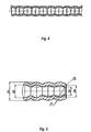
- fig. 4 is a cross sectional view of the middle part of the returning bush
- fig. 5 is an enlarged view of one of the returning bush ends in cross section.
- the piston 1, mounted for reciprocation within the guiding barrel 2 is in its firing position at the rear end of the guiding barrel 2 where the piston head 12 is as near as possible to the firing chamber 4.
- an elastic returning bush 7 which is in the shape of one piece bellows, made of an elastomer, whose diameters, both external and internal, are regularly varied.
- the walls of such formed returning bush 7 are configured to approximate in shape to a stack of frusto-spherical segments, creating uniformly spaced swellings and narrowings of a wave-like structure.
- the returning bush is of a shape of a stack of frusto-conical segments.
- the returning bush is of a shape of a stack of barrel-shaped segments or/and another surface of revolution segments.
- the returning bush 7 has the maximal internal diameter D4 of its two end segments at its both ends which is less than the respective diameter D2 of the remaining segments, so that the bush end segment walls are a little thicker than other segments walls.
- the internal end surface of the end segments is markedly curved outside in such a way that the position 71 of the curvature points of the bush ends is clearly distanced from the bush faces 72.
- the length of the returning bush 7 is selected in such a way that, after initial blocking of the returning bush 7, the piston shank 1 end face does not reach its extreme forward position and remains at a distance from the base 30; the distance is slightly greater than the height of the head of the fastening element 6.
- the maximal external diameter D1 of the returning bush 7 is smaller than the internal diameter of the guiding barrel 2, so that, after initial blocking of the returning bush 7, its external diameter still remains smaller than the internal diameter of the guiding barrel 2, thus preserving a small clearance.
- Ports A in the guiding barrel 2 and ports B and C in the external barrel 8 are provided to enable the firing gases to evacuate after firing.
- the firing gases set the piston 1 into motion with a rapidly accelerating velocity, towards the fastener 6.
- the piston head 12 after passing port A, opens the gas flow connection towards the space between the guiding barrel 2 and the external barrel 8 and from there, through port B, towards the silencer 81, and from there, via port C, into the atmosphere, thus reducing the firing noise and gas pressure in the firing chamber 4, to a value close to the atmospheric pressure.
- the accelerated piston 1 strikes against the fastening element 6, driving it into the base 30, and, at the same time, compressing the returning bush 7. At a distance of several millimeters before fully setting the fastening element 6 into the base 30, the initial blocking of the returning bush 7 takes place.
- the piston shank 1 end face does not reach its extreme forward position and remains at some distance from the base 30, which is slightly greater than the height of the head of the fastening element 6 and a clearance exists between the guiding barrel 2 and returning bush 7.
- the returning bush 7 in the final stage of the piston 1 motion forms a shut tubular column, thus absorbing the small firing energy which ensures driving the fastening element 6 to the full depth.
- this shut tubular column functions as a buffer, to absorb the high energy of the piston 1.
- the piston 1 stops and, due to the elastic memory inherent in the elastomeric material, the returning bush 7 returns the piston 1 to its firing position, where it is ready for the next firing operation, the more easily since the counter-pressure acting upon the piston 1 from the firing chamber 4 has fallen to the value of the atmospheric pressure.
- the springs of the firing pin assembly move the subassembly of the piston 1 and its guiding barrel 2 forward, by about a stroke, enabling: first to remove the used firing cartridge 9 from the firing chamber 4, and, secondly, after the tool is pressed anew against base 30 for the subsequent firing, to shift the cartridge belt 40 by one position.
- the specific wave-like shape of the returning bush 7, as well as the thickening of the end segments of the bush 7 and the particular position of the curvature points of the ends of the bush 7 ensure the correct functioning of the tool and eliminate the tendency of the elastomeric bush to curl, which tendency could lead to a situation when the piston 1 could be blocked within the guiding barrel 2.
- the returning bush 7 does not oppose a great resistance to the piston 1 movement , so it does not break its velocity or impair the effectiveness of fastening the fasteners and does not provoke any tool recoil effect.
Landscapes
- Engineering & Computer Science (AREA)
- Chemical & Material Sciences (AREA)
- Combustion & Propulsion (AREA)
- Mechanical Engineering (AREA)
- Portable Nailing Machines And Staplers (AREA)
Claims (4)
- Kraftbetätigtes Kolben-Werkzeug mit automatischer Kolbenrückführung, umfassend: ein äußeres Gehäuse (8) mit einem darin angeordneten Führungsgehäuse (2), einem Kolben (1), der in besagtem Führungsgehäuse montiert ist für eine Pendelbewegung zwischen der Feuerposition und der Befestigungsposition, einer Schlagbolzenanordnung, die am hinteren Ende des äußeren Gehäuses angeordnet ist und in Wirkverbindung mit ihm steht, und einem Mittel zur automatischen Rückführung des Kolbens von seiner Befestigungsposition in seine Feuerposition, wobei besagtes Mittel auf dem Kolbenschaft (11) zwischen dem Kolbenkopf (12) und der Befestigungselementsführung (5) für die automatische Kolbenrückführung angeordnet ist, wobei besagtes Mittel eine einstückige, elastische Rückführbuchse (7) ist, die aus einem elastomeren Material in Gestalt eines Balgs gemacht ist, dessen beide Außen- und Innendurchmesser regelmäßig variiert sind und dabei gleichmäßig beabstandete Verdickungen und Verengungen einer wellenartigen Struktur erzeugen, dadurch gekennzeichnet, dass die Rückführbuchse aus einer Mehrzahl von Segmenten besteht, wovon jedes der Segmente durch zwei Verengungen und eine Verdickung definiert wird, wobei der maximale Innendurchmesser (D4) wenigstens eines Segmentes der Rückführbuchse (7) an seinen beiden Enden kleiner ist als der entsprechende maximale Innendurchmesser (D2) der verbliebenen Segmente, wobei die Endsegmentwände der Rückführbuchse (7) dicker sind als die anderen Segmentwände, und dass die Innenendfläche der Endsegmente der Rückführbuchse (7) merklich nach außen gekrümmt ist in einer Weise, dass die Position der Krümmungsscheitel (71) der Buchsenenden von der Rückführbuchsenstimfläche (72) deutlich beabstandet sind.
- Kraftbetätigtes Kolben-Werkzeug nach Anspruch 1, dadurch gekennzeichnet, dass die Länge der Rückführbuchse (7), die Stärke ihrer Wände und der Wandneigungswinkel in einer Weise gewählt sind, dass nach Anfangsblockierung der Rückführbuchse (7) die Stirnfläche des Kolbenschaftes (11) nicht ihre vorderste Position erreicht und in einem Abstand zur Basis (30) verbleibt, wobei der Abstand größer als die Höhe des Kopfes des Befestigungselements (6) ist.
- Kraftbetätigtes Kolben-Werkzeug nach Anspruch 1 oder 2, dadurch gekennzeichnet, dass der maximale Außendurchmesser (D1) der Rückführbuchse (7) kleiner ist als der Innendurchmesser des Führungsgehäuses (2), so dass nach Anfangsblockierung der Rückführbuchse (7) deren Außendurchmesser noch kleiner bleibt als der Innendurchmesser des Führungsgehäuses (2), womit ein kleiner Spalt verbleibt.
- Kraftbetätigtes Kolben-Werkzeug nach Anspruch 1, dadurch gekennzeichnet, dass die Wände der Rückführbuchse (7) ausgebildet sind zur Annäherung in ihrer Form an eine Sinuskurve oder einen Stapel von kegel-sphärischen Segmenten oder an einen Stapel von kegel-konischen Segmenten oder an einen Stapel von fassförmigen Segmenten und/oder eine andere Oberfläche von Rotationssegmenten.
Applications Claiming Priority (3)
| Application Number | Priority Date | Filing Date | Title |
|---|---|---|---|
| PL98324361A PL185374B1 (pl) | 1998-01-19 | 1998-01-19 | Samorepetujący osadzak wybuchowy |
| PL32436198 | 1998-01-19 | ||
| PCT/PL1998/000052 WO1999036230A1 (en) | 1998-01-19 | 1998-12-31 | Power operated piston tool with piston automatic return |
Publications (2)
| Publication Number | Publication Date |
|---|---|
| EP1056570A1 EP1056570A1 (de) | 2000-12-06 |
| EP1056570B1 true EP1056570B1 (de) | 2006-07-05 |
Family
ID=20071386
Family Applications (1)
| Application Number | Title | Priority Date | Filing Date |
|---|---|---|---|
| EP98960123A Expired - Lifetime EP1056570B1 (de) | 1998-01-19 | 1998-12-31 | Kraftbetriebenes werkzeug mit kolben mit automatischem zurückfahren des kolbens |
Country Status (5)
| Country | Link |
|---|---|
| US (1) | US6824035B1 (de) |
| EP (1) | EP1056570B1 (de) |
| AU (1) | AU1579599A (de) |
| PL (1) | PL185374B1 (de) |
| WO (1) | WO1999036230A1 (de) |
Cited By (1)
| Publication number | Priority date | Publication date | Assignee | Title |
|---|---|---|---|---|
| DE102009016947A1 (de) | 2009-04-08 | 2010-10-14 | Fischerwerke Gmbh & Co. Kg | Brennkraftgetriebenes Setzgerät |
Families Citing this family (5)
| Publication number | Priority date | Publication date | Assignee | Title |
|---|---|---|---|---|
| US7328751B2 (en) * | 2004-10-28 | 2008-02-12 | Fci Americas Technology, Inc. | Powder operated tool |
| US7634912B2 (en) * | 2006-05-25 | 2009-12-22 | Raytheon Company | Methods and apparatus for actuator system |
| FR2931910B1 (fr) * | 2008-05-30 | 2013-02-22 | Snpe Materiaux Energetiques | Verin a course declenchee, notamment pour systeme de securite equipant un vehicule automobile. |
| CA2726559C (en) | 2009-12-30 | 2014-02-11 | Hubbel Incorporated | Powder actuated tool and connector |
| US8651464B2 (en) | 2011-07-08 | 2014-02-18 | Chung-Yi Lee | Resilient returning device for a power operated piston tool |
Citations (2)
| Publication number | Priority date | Publication date | Assignee | Title |
|---|---|---|---|---|
| EP0826464A1 (de) * | 1996-09-02 | 1998-03-04 | HILTI Aktiengesellschaft | Kolbenrückstellelement für pulverkraftbetriebenes Setzgerät |
| EP0881042A1 (de) * | 1997-05-30 | 1998-12-02 | HILTI Aktiengesellschaft | Setzgerät mit Rückstellelement für den Treibkolben |
Family Cites Families (17)
| Publication number | Priority date | Publication date | Assignee | Title |
|---|---|---|---|---|
| DE1103775B (de) * | 1957-08-16 | 1961-03-30 | Paul Henss | Gummihohlfeder fuer Fahrzeuge, insbesondere Kraftfahrzeuge |
| DE1811684U (de) * | 1960-03-23 | 1960-05-19 | Porsche Kg | Teleskopstossdaempfer fuer kraftfahrzeuge. |
| US3263985A (en) * | 1963-08-07 | 1966-08-02 | Planta Kurt | Shock absorber |
| US3272491A (en) * | 1964-03-03 | 1966-09-13 | Union Carbide Corp | Resilient spring |
| US3331546A (en) * | 1965-06-01 | 1967-07-18 | Olin Mathieson | Piston return and buffer system |
| FR2052186A5 (de) * | 1969-07-25 | 1971-04-09 | Jarret Jacques | |
| DE2632413A1 (de) * | 1976-07-19 | 1978-01-26 | Hilti Ag | Pulverkraftbetriebenes bolzensetzgeraet mit einer abfangvorrichtung fuer den treibkolben |
| JPS5922094Y2 (ja) * | 1979-12-13 | 1984-07-02 | ワイケイケイ株式会社 | 釦取付装置 |
| DE3151771C2 (de) * | 1981-12-29 | 1986-10-23 | Metzeler Kautschuk GmbH, 8000 München | Anschlagpuffer |
| IT8353494V0 (it) * | 1983-06-23 | 1983-06-23 | Riv Officine Di Villar Perosa | Tassello elastico per l attacco superiore di un ammortizzatore di una sospensione anteriore di un veicolo alla scocca del medesimo |
| FR2559862B1 (fr) * | 1984-02-21 | 1988-07-15 | Ouest Cie | Butee progressive, notamment pour amortisseur de suspension |
| US4591030A (en) * | 1984-04-16 | 1986-05-27 | Tayco Developments, Inc. | Elastomeric damped shock absorber |
| GB8500605D0 (en) * | 1985-01-10 | 1985-02-13 | Secretary Trade Ind Brit | Damped spring |
| DE3540953A1 (de) | 1985-11-19 | 1987-05-21 | Hilti Ag | Pulverkraftbetriebenes bolzensetzgeraet |
| DK156257C (da) * | 1987-08-11 | 1989-12-04 | Anders Sten Wedell | Rotationssymmetrisk fjeder til at fjedre i hovedsagen i aksial retning |
| US5240269A (en) * | 1992-01-16 | 1993-08-31 | Miner Enterprises, Inc. | Bike suspension |
| DE19509763A1 (de) * | 1995-03-17 | 1996-09-19 | Wuerth Adolf Gmbh & Co Kg | Bolzensetzgerät |
-
1998
- 1998-01-19 PL PL98324361A patent/PL185374B1/pl not_active IP Right Cessation
- 1998-12-31 US US09/582,890 patent/US6824035B1/en not_active Expired - Lifetime
- 1998-12-31 AU AU15795/99A patent/AU1579599A/en not_active Abandoned
- 1998-12-31 WO PCT/PL1998/000052 patent/WO1999036230A1/en active IP Right Grant
- 1998-12-31 EP EP98960123A patent/EP1056570B1/de not_active Expired - Lifetime
Patent Citations (2)
| Publication number | Priority date | Publication date | Assignee | Title |
|---|---|---|---|---|
| EP0826464A1 (de) * | 1996-09-02 | 1998-03-04 | HILTI Aktiengesellschaft | Kolbenrückstellelement für pulverkraftbetriebenes Setzgerät |
| EP0881042A1 (de) * | 1997-05-30 | 1998-12-02 | HILTI Aktiengesellschaft | Setzgerät mit Rückstellelement für den Treibkolben |
Cited By (2)
| Publication number | Priority date | Publication date | Assignee | Title |
|---|---|---|---|---|
| DE102009016947A1 (de) | 2009-04-08 | 2010-10-14 | Fischerwerke Gmbh & Co. Kg | Brennkraftgetriebenes Setzgerät |
| WO2010115505A1 (de) | 2009-04-08 | 2010-10-14 | Fischerwerke Gmbh & Co. Kg | Brennkraftgetriebenes setzgerät |
Also Published As
| Publication number | Publication date |
|---|---|
| EP1056570A1 (de) | 2000-12-06 |
| PL324361A1 (en) | 1999-08-02 |
| AU1579599A (en) | 1999-08-02 |
| PL185374B1 (pl) | 2003-04-30 |
| WO1999036230A1 (en) | 1999-07-22 |
| US6824035B1 (en) | 2004-11-30 |
Similar Documents
| Publication | Publication Date | Title |
|---|---|---|
| US7131367B1 (en) | Hydraulic bolt buffer for firearm | |
| US6668478B2 (en) | Firearm pneumatic counter-recoil modulator & airgun thrust-adjustor | |
| US4824003A (en) | Indirect firing fastener driving tool | |
| US5349938A (en) | Reciprocatable barrel pneumatic gun | |
| US3331546A (en) | Piston return and buffer system | |
| US4771758A (en) | Air weapon with air compression system having grooves for air transfer | |
| US10415907B1 (en) | Firearm buffer with biasing member | |
| CA1057901A (en) | Damping device for a fastening element setting gun | |
| US11022385B2 (en) | Operating system for small caliber rifles | |
| EP1056570B1 (de) | Kraftbetriebenes werkzeug mit kolben mit automatischem zurückfahren des kolbens | |
| US4091981A (en) | Power driven percussion tool | |
| US3066302A (en) | Power tool | |
| US6234062B1 (en) | Telescopic piston | |
| US5224465A (en) | Air gun with baffle for limiting maximum velocity | |
| GB1566620A (en) | Fastener driving tool | |
| KR100354367B1 (ko) | 액기압식완충장치를구비한폭발력작동식핀타정장치 | |
| US4332340A (en) | Piston tool buffer assembly | |
| US20200072569A1 (en) | 3-cycle 2-stroke damper | |
| EP0732178B1 (de) | Bolzensetzgerät | |
| KR20020043209A (ko) | 충격 공구 | |
| US6715399B2 (en) | Firearm bolt assembly | |
| US6964220B1 (en) | Floating barrel handgun method of recoil elimination | |
| US3044071A (en) | Explosive actuated tool | |
| US7275472B1 (en) | Gas ring for firearm | |
| CN111288841B (zh) | 导气式自动机多功能气动装置 |
Legal Events
| Date | Code | Title | Description |
|---|---|---|---|
| PUAI | Public reference made under article 153(3) epc to a published international application that has entered the european phase |
Free format text: ORIGINAL CODE: 0009012 |
|
| 17P | Request for examination filed |
Effective date: 20000817 |
|
| AK | Designated contracting states |
Kind code of ref document: A1 Designated state(s): AT CH DE DK ES FI GB LI SE |
|
| 17Q | First examination report despatched |
Effective date: 20021106 |
|
| GRAP | Despatch of communication of intention to grant a patent |
Free format text: ORIGINAL CODE: EPIDOSNIGR1 |
|
| GRAS | Grant fee paid |
Free format text: ORIGINAL CODE: EPIDOSNIGR3 |
|
| GRAA | (expected) grant |
Free format text: ORIGINAL CODE: 0009210 |
|
| AK | Designated contracting states |
Kind code of ref document: B1 Designated state(s): AT CH DE DK ES FI GB LI SE |
|
| PG25 | Lapsed in a contracting state [announced via postgrant information from national office to epo] |
Ref country code: LI Free format text: LAPSE BECAUSE OF FAILURE TO SUBMIT A TRANSLATION OF THE DESCRIPTION OR TO PAY THE FEE WITHIN THE PRESCRIBED TIME-LIMIT Effective date: 20060705 Ref country code: FI Free format text: LAPSE BECAUSE OF FAILURE TO SUBMIT A TRANSLATION OF THE DESCRIPTION OR TO PAY THE FEE WITHIN THE PRESCRIBED TIME-LIMIT Effective date: 20060705 Ref country code: CH Free format text: LAPSE BECAUSE OF FAILURE TO SUBMIT A TRANSLATION OF THE DESCRIPTION OR TO PAY THE FEE WITHIN THE PRESCRIBED TIME-LIMIT Effective date: 20060705 Ref country code: AT Free format text: LAPSE BECAUSE OF FAILURE TO SUBMIT A TRANSLATION OF THE DESCRIPTION OR TO PAY THE FEE WITHIN THE PRESCRIBED TIME-LIMIT Effective date: 20060705 |
|
| REG | Reference to a national code |
Ref country code: GB Ref legal event code: FG4D |
|
| REG | Reference to a national code |
Ref country code: CH Ref legal event code: EP |
|
| REF | Corresponds to: |
Ref document number: 69835168 Country of ref document: DE Date of ref document: 20060817 Kind code of ref document: P |
|
| PG25 | Lapsed in a contracting state [announced via postgrant information from national office to epo] |
Ref country code: SE Free format text: LAPSE BECAUSE OF FAILURE TO SUBMIT A TRANSLATION OF THE DESCRIPTION OR TO PAY THE FEE WITHIN THE PRESCRIBED TIME-LIMIT Effective date: 20061005 Ref country code: DK Free format text: LAPSE BECAUSE OF FAILURE TO SUBMIT A TRANSLATION OF THE DESCRIPTION OR TO PAY THE FEE WITHIN THE PRESCRIBED TIME-LIMIT Effective date: 20061005 |
|
| PG25 | Lapsed in a contracting state [announced via postgrant information from national office to epo] |
Ref country code: DE Free format text: LAPSE BECAUSE OF FAILURE TO SUBMIT A TRANSLATION OF THE DESCRIPTION OR TO PAY THE FEE WITHIN THE PRESCRIBED TIME-LIMIT Effective date: 20061006 |
|
| PG25 | Lapsed in a contracting state [announced via postgrant information from national office to epo] |
Ref country code: ES Free format text: LAPSE BECAUSE OF FAILURE TO SUBMIT A TRANSLATION OF THE DESCRIPTION OR TO PAY THE FEE WITHIN THE PRESCRIBED TIME-LIMIT Effective date: 20061016 |
|
| PLBE | No opposition filed within time limit |
Free format text: ORIGINAL CODE: 0009261 |
|
| STAA | Information on the status of an ep patent application or granted ep patent |
Free format text: STATUS: NO OPPOSITION FILED WITHIN TIME LIMIT |
|
| 26N | No opposition filed |
Effective date: 20070410 |
|
| GBPC | Gb: european patent ceased through non-payment of renewal fee |
Effective date: 20061231 |
|
| PG25 | Lapsed in a contracting state [announced via postgrant information from national office to epo] |
Ref country code: GB Free format text: LAPSE BECAUSE OF NON-PAYMENT OF DUE FEES Effective date: 20061231 |