EP1056558B1 - Vorrichtung zum horizontalen stranggiessen von profilen, insbesondere von metallbändern - Google Patents
Vorrichtung zum horizontalen stranggiessen von profilen, insbesondere von metallbändern Download PDFInfo
- Publication number
- EP1056558B1 EP1056558B1 EP99904608A EP99904608A EP1056558B1 EP 1056558 B1 EP1056558 B1 EP 1056558B1 EP 99904608 A EP99904608 A EP 99904608A EP 99904608 A EP99904608 A EP 99904608A EP 1056558 B1 EP1056558 B1 EP 1056558B1
- Authority
- EP
- European Patent Office
- Prior art keywords
- casting
- die
- mold
- receptacle
- ramming
- Prior art date
- Legal status (The legal status is an assumption and is not a legal conclusion. Google has not performed a legal analysis and makes no representation as to the accuracy of the status listed.)
- Expired - Lifetime
Links
Images


Classifications
-
- B—PERFORMING OPERATIONS; TRANSPORTING
- B22—CASTING; POWDER METALLURGY
- B22D—CASTING OF METALS; CASTING OF OTHER SUBSTANCES BY THE SAME PROCESSES OR DEVICES
- B22D11/00—Continuous casting of metals, i.e. casting in indefinite lengths
- B22D11/04—Continuous casting of metals, i.e. casting in indefinite lengths into open-ended moulds
- B22D11/045—Continuous casting of metals, i.e. casting in indefinite lengths into open-ended moulds for horizontal casting
-
- B—PERFORMING OPERATIONS; TRANSPORTING
- B22—CASTING; POWDER METALLURGY
- B22D—CASTING OF METALS; CASTING OF OTHER SUBSTANCES BY THE SAME PROCESSES OR DEVICES
- B22D11/00—Continuous casting of metals, i.e. casting in indefinite lengths
- B22D11/04—Continuous casting of metals, i.e. casting in indefinite lengths into open-ended moulds
- B22D11/045—Continuous casting of metals, i.e. casting in indefinite lengths into open-ended moulds for horizontal casting
- B22D11/047—Means for joining tundish to mould
Definitions
- the invention relates to a device for horizontal continuous casting of profiles, in particular of metal strips, with a receptacle for the Molten metal, preferably a holding furnace, one to the receptacle mold can be connected via a ramming frame, its shaping Pouring a fireproof lining that cannot be exposed to the molten metal has, and with a vibration drive for the mold in the casting direction.
- the Forming mold forming mold over a ramming frame to a receptacle connected for the molten metal, either from a Holding furnace exists or via a holding furnace with the molten metal can be loaded.
- the ramming frame usually forms with it ceramic ramming compound a refractory lining in the transition area between the receptacle and the mold, so that the metallic housing the mold is connected to the receptacle in a comparatively simple manner can be.
- the invention is therefore based on the object of a device for horizontal Continuous casting of profiles of the type described in such a way that the opposite the receptacle for the molten metal swinging back and forth in the casting direction drivable mold advantageously sealed against the receptacle can be.
- the invention solves this problem in that the mold is mounted on a displacement guide assigned to the receptacle and extending in the casting direction, that the vibration drive is supported on the one hand on the receptacle and on the other on the mold and that in the transition area between the receptacle and the mold with a minimum pressure
- nonwoven fabric made of refractory fibers that are not wettable by the molten metal is provided as a seal against the molten metal.
- the mass to be moved in an oscillating manner is essentially limited to the mold mass, which is low compared to the receptacle, which is an advantageous prerequisite for precise vibration control represents frequencies and amplitudes that can be predetermined by the program.
- a mounting of the mold that is capable of vibrating with respect to the receptacle is only possible if a seal can be provided between the vibrating mold and the fixed receptacle that can withstand all mechanical, metallurgical and thermal loads during an operating time that is adapted to the service life of the mold.
- Such a seal is obtained by a nonwoven fabric that is biased with a minimum pressure corresponding to the hydraulic pressure of the molten metal, so that this nonwoven fabric cannot be pressed away from a sealing surface by the molten metal.
- This pretensioning of the nonwoven thus ensures the tight contact of the nonwoven with the sealing surfaces, the inherent elasticity of the nonwoven permitting the absorption of the mold vibrations without further ado, if appropriate dimensioning of the nonwoven is ensured.
- the fibers of this fleece must be fire-proof and must not be wetted by the molten metal.
- the nonwettability of the nonwoven fibers by the molten metal closes penetration of the molten metal into the pores between the fibers of the Fleece does not penetrate, as does the pretension of the fleece the metal melt can not prevent.
- the one for the inert gas The additional cost of the nonwoven can be necessary in view of the circumstance be kept small, that it is common, also the ramming mass of the ramming frame to apply such a protective gas.
- the mold firmly connected to the ramming frame under tension of the nonwoven fabric between the ramming frame and a mold connection surface of the receptacle are resiliently clamped against the receptacle.
- the elastic properties of the nonwoven fabric exploited because the nonwoven fabric is essentially perpendicular to the direction of vibration the mold is arranged.
- the resilient bias of the The nonwoven fabric is compared to the elastic tension of the mold Receiving vessel reached, the vibration drive against this spring load must take effect.
- the mold becomes opposite the vessel-fixed one
- the ramming frame is slidably mounted, with the non-woven fabric that is in the Stamping frame engaging lining of the casting gap belonging to the mold encloses by the ramming mass of the ramming frame with pressure is applied and pressed against the lining of the casting gap.
- the Lining of the casting gap is thus within the enclosing, from The ramming of the fiber fleece held back and forth, where there is a sliding friction between the lining and the nonwoven results.
- the pre-tension of the non-woven fabric over the ramming mass of the ramming frame causes in connection with the inherent elasticity of the nonwoven again a secure contact of the nonwoven fabric on the sealing surface, which in this Embodiment is formed by the lining of the casting gap.
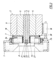
- the device according to the embodiment shown in FIGS. 1 and 2 has one that is not shown for clarity
- Receiving vessel for the metal melt associated lead frame 1 for a Chill mold 2 which has a shaping casting gap 3 in a conventional manner forms, which has a lining 4 of graphite plates.
- To cool the Chill molds are made of copper-made cooling plates through which a coolant flows 5, which are clamped together via pressure plates of a housing 6.
- a ramming frame 7 is flanged to the housing 6 of the mold 2
- Pounding compound 8 a refractory lining of the mold 2 compared to the Receptacle forms.
- a fleece 13 made of carbon fibers is provided between the ramming frame 7 and the lead frame 1 is clamped.
- the Guide rods 10 of the displacement guide 9 with a threaded section 14 provided, on which a plate spring assembly 15 is arranged, which on the one hand a housing attachment encompassing the respective guide rod 10 in a fork-like manner 16 and on the other hand on a clamping nut 17 on the threaded section 14 supported.
- the mold housing 6 can also be provided with the clamping nut 17 the ramming frame 7 resiliently clamped against the lead frame 1 be, wherein the nonwoven fabric 13 is subjected to a bias.
- This Bias should be at least the hydraulic pressure of the molten metal in the Area of the nonwoven 13 correspond to prevent the nonwoven 13 stands out from the ramming frame 7 or from the lead frame 1.
- a vibration drive 18 is provided, the one hand supported on the lead frame 1 and on the other hand on the mold housing 6, such as this shows Fig. 1. With the help of this vibration drive 18 can accordingly the mold 2 are driven to vibrate, the vibration amplitudes about the inherent elasticity of the nonwoven fabric 13 are included.
- Via connection holes 19 in the ramming frame 7 shielding gas both the ramming mass 8 and the nonwoven fabric 13 can be fed under a pressure, which corresponds at least to the hydraulic pressure of the molten metal, can Penetration of the molten metal into the carbon fiber fleece 13 or into the ramming compound 8 can be prevented simply and effectively.
- the flooding of the mold 2 with Shielding gas also prevents oxygen supply to the graphite lining 4, which excludes their burning.
- the inlet part 20 of the Pouring gap 3 is formed offset from the subsequent pouring gap 3, by corresponding moldings 21 being inserted into the casting gap 3.
- the inlet part 20 of the casting gap 3 through inserts 22 Width can be divided into several sections, which is advantageous on the Course of the solidification front of the metal strip affects.
- an additional seal 23 made of refractory, ghrititized Cords are provided, which are mounted on the lead frame 1 and the Enclose the ramming frame 7.
- This seal 23 is made with the help of Hydraulic cylinder 24 openable pressure bars 25 against the ramming frame 7 pressed.
- the device according to the embodiment of FIG. 3 differs compared to the device according to FIGS. 1 and 2 essentially only characterized in that the ramming frame 7 with the lead frame 1 via screws 26 is rigidly connected, while the housing 6 of the mold 2 from the ramming frame 7 separately on a sliding guide of the receptacle in Casting direction is slidably mounted.
- the shift guide can be accordingly the sliding guide of the embodiment of FIG. 1st be trained.
Landscapes
- Engineering & Computer Science (AREA)
- Mechanical Engineering (AREA)
- Continuous Casting (AREA)
- Treatment Of Steel In Its Molten State (AREA)
Description
Durch die dem Aufnahmegefäß zugeordnete, in Gießrichtung verlaufende Verschiebeführung für die Kokille und den zwischen dem Aufnahmegefäß und der Kokille angreifenden Schwingungsantrieb wird die oszillierend zu bewegende Masse im wesentlichen auf die im Vergleich zum Aufnahmegefäß geringe Kokillenmasse beschränkt, was eine vorteilhafte Voraussetzung für eine genaue Schwingungssteuerung mit programmbedingt vorgebbaren Frequenzen und Amplituden darstellt. Eine solche gegenüber dem Aufnahmegefäß schwingungsfähige Lagerung der Kokille ist jedoch nur möglich, wenn zwischen der schwingenden Kokille und dem feststehenden Aufnahmegefäß eine Dichtung vorgesehen werden kann, die allen mechanischen, metallurgischen und wärmetechnischen Belastungen während einer an die Standzeit der Kokille angepaßten Betriebszeit standhalten kann. Eine solche Dichtung wird durch ein Faservlies erhalten, das mit einem Mindestdruck entsprechend dem Hydraulikdruck der Metallschmelze vorgespannt wird, so daß dieses Faservlies nicht durch die Metallschmelze von einer Dichtfläche weggedrückt werden kann. Diese Vorspannung des Faservlieses sichert somit die dichte Anlage des Vlieses an den Dichtflächen, wobei die Eigenelastizität des Vlieses die Aufnahme der Kokillenschwingungen ohne weiteres zuläßt, wenn für eine entsprechende Dimensionierung des Faservlieses gesorgt wird. Die Fasern dieses Vlieses müssen feuerfest sein und dürfen von der Metallschmelze nicht benetzt werden. Diese Bedingungen werden von Kohlefasern vorteilhaft erfüllt, obwohl auch andere Fasermaterialen eingesetzt werden können.
- Fig. 1
- eine erfindungsgemäße Vorrichtung zum honzontalen Stranggießen eines Metallbandes in einer zum Teil aufgerissenen Seitenansicht,
- Fig. 2
- die Vorrichtung nach der Fig. 1 in einem Vertikalschnitt und
- Fig. 3
- eine der Fig. 2 entsprechende Darstellung einer Konstruktionsvariante.
Claims (3)
- Vorrichtung zum horizonalen Stranggießen von Profilen, insbesondere von Metallbändern, mit einem Aufnahmegefäß für die Metallschmelze, vorzugsweise einem Warmhalteofen, einer an das Aufnahmegefäß über einen Stampfrahmen (7) anschließbaren Kokille (2), deren formgebender Gießspalt (3) eine feuerfeste, von der Metallschmelze unbenetzbare Auskleidung (4) aufweist, und mit einem Schwingungsantrieb (18) für die Kokille (2) in Gießrichtung, dadurch gekennzeichnet, daß die Kokille (2) auf einer dem Aufnahmegefäß zugeordneten, in Gießrichtung verlaufenden Verschiebeführung (9) lagert, daß sich der Schwingungsantrieb (18) einerseits am Aufnahmegefäß und anderseits an der Kokille (2) abstützt und daß im Übergangsbereich zwischen dem Aufnahmegefäß und der Kokille (2) ein mit einem Mindestdruck entsprechend dem Hydraulikdruck der Metallschmelze vorgespanntes Vlies (13) aus feuerfesten, von der Metallschmelze unbenetzbaren Fasern (13) als Dichtung gegenüber der Metallschmelze vorgesehen ist.
- Vorrichtung nach Anspruch 1, dadurch gekennzeichnet, daß die verschiebefest mit dem Stampfrahmen (7) verbundene Kokille (2) unter Einspannung des Faservlieses (13) zwischen dem Stampfrahmen (7) und einer Kokillenanschlußfläche (12) des Aufnahmegefäßes federnd gegen das Aufnahmegefäß spannbar ist.
- Vorrichtung nach Anspruch 1, dadurch gekennzeichnet, daß die Kokille (2) gegenüber dem gefäßfesten Stampfrahmen (7) verschiebbar gelagert ist und daß das durch die Stampfmasse (8) des Stampfrahmens (7) quer zum Gießspalt (3) druckbeaufschlagte Faservlies (13) die in den Stampfrahmen (7) eingreifende, der Kokille (2) zugehörige Auskleidung (4) des Gießspaltes (3) umschließt.
Applications Claiming Priority (3)
| Application Number | Priority Date | Filing Date | Title |
|---|---|---|---|
| AT0028498A AT407350B (de) | 1998-02-18 | 1998-02-18 | Vorrichtung zum horizontalen stranggiessen von profilen, insbesondere von metallbändern |
| AT28498 | 1998-02-18 | ||
| PCT/AT1999/000042 WO1999042235A1 (de) | 1998-02-18 | 1999-02-17 | Vorrichtung zum horizontalen stranggiessen von profilen, insbesondere von metallbändern |
Publications (2)
| Publication Number | Publication Date |
|---|---|
| EP1056558A1 EP1056558A1 (de) | 2000-12-06 |
| EP1056558B1 true EP1056558B1 (de) | 2002-11-13 |
Family
ID=3486462
Family Applications (1)
| Application Number | Title | Priority Date | Filing Date |
|---|---|---|---|
| EP99904608A Expired - Lifetime EP1056558B1 (de) | 1998-02-18 | 1999-02-17 | Vorrichtung zum horizontalen stranggiessen von profilen, insbesondere von metallbändern |
Country Status (6)
| Country | Link |
|---|---|
| US (1) | US6554055B1 (de) |
| EP (1) | EP1056558B1 (de) |
| JP (1) | JP2002503555A (de) |
| AT (2) | AT407350B (de) |
| DE (1) | DE59903396D1 (de) |
| WO (1) | WO1999042235A1 (de) |
Family Cites Families (7)
| Publication number | Priority date | Publication date | Assignee | Title |
|---|---|---|---|---|
| US3857437A (en) * | 1973-03-22 | 1974-12-31 | Technicon Instr | Method and apparatus for continuously casting metals |
| DE3037059A1 (de) * | 1980-10-01 | 1982-04-29 | Böhler AG, 4000 Düsseldorf | Stranggussvorrichtung |
| DE3123704A1 (de) * | 1981-06-15 | 1982-12-30 | SMS Schloemann-Siemag AG, 4000 Düsseldorf | Vorrichtung zum strangiessen von stahl in einem geschlossenen eingiesssystem |
| US4640336A (en) * | 1984-10-01 | 1987-02-03 | Toshiba Ceramics Co., Ltd. | Refractory for continuous casting |
| JPS61273244A (ja) * | 1985-05-28 | 1986-12-03 | Hitachi Zosen Corp | 水平連続鋳造設備 |
| US4744406A (en) * | 1986-10-30 | 1988-05-17 | Chaparral Steel Company | Horizontal continuous casting apparatus with break ring formed integral with mold |
| US4802436A (en) * | 1987-07-21 | 1989-02-07 | Williams Gold Refining Company | Continuous casting furnace and die system of modular design |
-
1998
- 1998-02-18 AT AT0028498A patent/AT407350B/de not_active IP Right Cessation
-
1999
- 1999-02-17 DE DE59903396T patent/DE59903396D1/de not_active Expired - Fee Related
- 1999-02-17 JP JP2000532229A patent/JP2002503555A/ja active Pending
- 1999-02-17 WO PCT/AT1999/000042 patent/WO1999042235A1/de not_active Ceased
- 1999-02-17 AT AT99904608T patent/ATE227618T1/de not_active IP Right Cessation
- 1999-02-17 US US09/622,330 patent/US6554055B1/en not_active Expired - Fee Related
- 1999-02-17 EP EP99904608A patent/EP1056558B1/de not_active Expired - Lifetime
Also Published As
| Publication number | Publication date |
|---|---|
| US6554055B1 (en) | 2003-04-29 |
| DE59903396D1 (de) | 2002-12-19 |
| WO1999042235A1 (de) | 1999-08-26 |
| ATA28498A (de) | 2000-07-15 |
| EP1056558A1 (de) | 2000-12-06 |
| AT407350B (de) | 2001-02-26 |
| ATE227618T1 (de) | 2002-11-15 |
| JP2002503555A (ja) | 2002-02-05 |
Similar Documents
| Publication | Publication Date | Title |
|---|---|---|
| DE1296747B (de) | Vorrichtung zur Zufuhr einer metallischen Schmelze aus einem Vorratsbehaelter | |
| EP0244354A2 (de) | Mehrteilige Giessdüse zum Einführen von Metallschmelze in den Giessraum einer Stranggiessmaschine | |
| DE3546148A1 (de) | Vorrichtung zur herstellung von verbundwerkstoff | |
| DE2401145A1 (de) | Verfahren und vorrichtung zum kontinuierlichen giessen | |
| EP0237478A1 (de) | Abdichtung einer Giessdüse gegen den Giessraum einer Stranggiessvorrichtung mit mindestens einem umlaufenden, flexiblen Kokillenband | |
| DE60003505T2 (de) | Großflächige Kokille zum vertikalen Stranggießen mit Einsatz von Metallen | |
| DE69803071T2 (de) | Stranggiesskokille mit warmhaube zum vertikalstranggiessen von langgestreckten metallischen gegenständen | |
| DE3415235C2 (de) | Zuführeinrichtung zum Einbringen von Stahlschmelze in Doppelbandgießmaschinen | |
| DE19547779A1 (de) | Stranggießkokille | |
| EP1019207B2 (de) | Stranggiesseinrichtung | |
| AT407350B (de) | Vorrichtung zum horizontalen stranggiessen von profilen, insbesondere von metallbändern | |
| DE2952978C1 (de) | Vorrichtung zur gasdynamischen Durchmischung von fluessigem Metall und gleichzeitiger Raffination mit einem Behandlungsgas in einem Behaelter | |
| EP2037088B1 (de) | Pleuel | |
| EP0965401A1 (de) | Kokillenwand einer Stranggiesskokille | |
| WO2005105342A1 (de) | Vorrichtung für die aufnahme einer stranggiesskokille auf einem hubtisch zum giessen von flüssigen metallen, insbesondere von flüssigen stahlwerkstoffen | |
| AT508395B1 (de) | Mittel zum oszillieren einer stranggiesskokille | |
| DE1104124B (de) | Verfahren zum Zufuehren des Gleitmittels in eine Kokille mit horizontal liegender Achse zum kontinuierlichen Giessen von Metallen | |
| EP0049239B1 (de) | Stranggussvorrichtung | |
| EP2006523A1 (de) | Kreuzkopf-Grossdieselmotor | |
| DE8304858U1 (de) | Einlegevorrichtung für einen Glasschmelzofen | |
| DE3426170C2 (de) | Anfahrkopf für das Stranggießen von Metallen, insbesondere von Stahl | |
| EP0246423A2 (de) | Verfahren und Vorrichtung zur festen Verbindung von keramischen Formteilen mit Metallen | |
| DE2539669A1 (de) | Mantel fuer eine sinterelektrode | |
| DE2703148A1 (de) | Stranggiessanlage | |
| DE1945141A1 (de) | Einrichtung zum horizontalen Stranggiessen |
Legal Events
| Date | Code | Title | Description |
|---|---|---|---|
| PUAI | Public reference made under article 153(3) epc to a published international application that has entered the european phase |
Free format text: ORIGINAL CODE: 0009012 |
|
| 17P | Request for examination filed |
Effective date: 20000829 |
|
| AK | Designated contracting states |
Kind code of ref document: A1 Designated state(s): AT CH DE FR GB IT LI |
|
| 17Q | First examination report despatched |
Effective date: 20010820 |
|
| GRAG | Despatch of communication of intention to grant |
Free format text: ORIGINAL CODE: EPIDOS AGRA |
|
| GRAG | Despatch of communication of intention to grant |
Free format text: ORIGINAL CODE: EPIDOS AGRA |
|
| GRAH | Despatch of communication of intention to grant a patent |
Free format text: ORIGINAL CODE: EPIDOS IGRA |
|
| GRAH | Despatch of communication of intention to grant a patent |
Free format text: ORIGINAL CODE: EPIDOS IGRA |
|
| GRAA | (expected) grant |
Free format text: ORIGINAL CODE: 0009210 |
|
| AK | Designated contracting states |
Kind code of ref document: B1 Designated state(s): AT CH DE FR GB IT LI |
|
| PG25 | Lapsed in a contracting state [announced via postgrant information from national office to epo] |
Ref country code: IT Free format text: LAPSE BECAUSE OF FAILURE TO SUBMIT A TRANSLATION OF THE DESCRIPTION OR TO PAY THE FEE WITHIN THE PRESCRIBED TIME-LIMIT;WARNING: LAPSES OF ITALIAN PATENTS WITH EFFECTIVE DATE BEFORE 2007 MAY HAVE OCCURRED AT ANY TIME BEFORE 2007. THE CORRECT EFFECTIVE DATE MAY BE DIFFERENT FROM THE ONE RECORDED. Effective date: 20021113 Ref country code: FR Free format text: LAPSE BECAUSE OF FAILURE TO SUBMIT A TRANSLATION OF THE DESCRIPTION OR TO PAY THE FEE WITHIN THE PRESCRIBED TIME-LIMIT Effective date: 20021113 |
|
| REF | Corresponds to: |
Ref document number: 227618 Country of ref document: AT Date of ref document: 20021115 Kind code of ref document: T |
|
| REG | Reference to a national code |
Ref country code: GB Ref legal event code: FG4D Free format text: NOT ENGLISH |
|
| REG | Reference to a national code |
Ref country code: CH Ref legal event code: EP |
|
| REF | Corresponds to: |
Ref document number: 59903396 Country of ref document: DE Date of ref document: 20021219 |
|
| REG | Reference to a national code |
Ref country code: CH Ref legal event code: NV Representative=s name: E. BLUM & CO. PATENTANWAELTE |
|
| PG25 | Lapsed in a contracting state [announced via postgrant information from national office to epo] |
Ref country code: AT Free format text: LAPSE BECAUSE OF NON-PAYMENT OF DUE FEES Effective date: 20030217 |
|
| GBT | Gb: translation of ep patent filed (gb section 77(6)(a)/1977) |
Effective date: 20030212 |
|
| EN | Fr: translation not filed | ||
| PLBE | No opposition filed within time limit |
Free format text: ORIGINAL CODE: 0009261 |
|
| STAA | Information on the status of an ep patent application or granted ep patent |
Free format text: STATUS: NO OPPOSITION FILED WITHIN TIME LIMIT |
|
| 26N | No opposition filed |
Effective date: 20030814 |
|
| PGFP | Annual fee paid to national office [announced via postgrant information from national office to epo] |
Ref country code: DE Payment date: 20060213 Year of fee payment: 8 |
|
| PGFP | Annual fee paid to national office [announced via postgrant information from national office to epo] |
Ref country code: CH Payment date: 20060217 Year of fee payment: 8 |
|
| PG25 | Lapsed in a contracting state [announced via postgrant information from national office to epo] |
Ref country code: LI Free format text: LAPSE BECAUSE OF NON-PAYMENT OF DUE FEES Effective date: 20070228 Ref country code: CH Free format text: LAPSE BECAUSE OF NON-PAYMENT OF DUE FEES Effective date: 20070228 |
|
| REG | Reference to a national code |
Ref country code: CH Ref legal event code: PL |
|
| GBPC | Gb: european patent ceased through non-payment of renewal fee |
Effective date: 20070217 |
|
| PG25 | Lapsed in a contracting state [announced via postgrant information from national office to epo] |
Ref country code: DE Free format text: LAPSE BECAUSE OF NON-PAYMENT OF DUE FEES Effective date: 20070901 |
|
| PG25 | Lapsed in a contracting state [announced via postgrant information from national office to epo] |
Ref country code: GB Free format text: LAPSE BECAUSE OF NON-PAYMENT OF DUE FEES Effective date: 20070217 |
|
| PGFP | Annual fee paid to national office [announced via postgrant information from national office to epo] |
Ref country code: GB Payment date: 20060206 Year of fee payment: 8 |