EP1055277B1 - Leiterbahnen mit Kommutatorbürsten für eine elektrische Antriebseinheit für Fahrzeugaggregate - Google Patents
Leiterbahnen mit Kommutatorbürsten für eine elektrische Antriebseinheit für Fahrzeugaggregate Download PDFInfo
- Publication number
- EP1055277B1 EP1055277B1 EP99941395A EP99941395A EP1055277B1 EP 1055277 B1 EP1055277 B1 EP 1055277B1 EP 99941395 A EP99941395 A EP 99941395A EP 99941395 A EP99941395 A EP 99941395A EP 1055277 B1 EP1055277 B1 EP 1055277B1
- Authority
- EP
- European Patent Office
- Prior art keywords
- commutator
- drive unit
- housing
- brushes
- stamped grid
- Prior art date
- Legal status (The legal status is an assumption and is not a legal conclusion. Google has not performed a legal analysis and makes no representation as to the accuracy of the status listed.)
- Expired - Lifetime
Links
Images

Classifications
-
- H—ELECTRICITY
- H02—GENERATION; CONVERSION OR DISTRIBUTION OF ELECTRIC POWER
- H02K—DYNAMO-ELECTRIC MACHINES
- H02K5/00—Casings; Enclosures; Supports
- H02K5/04—Casings or enclosures characterised by the shape, form or construction thereof
- H02K5/14—Means for supporting or protecting brushes or brush holders
- H02K5/143—Means for supporting or protecting brushes or brush holders for cooperation with commutators
- H02K5/145—Fixedly supported brushes or brush holders, e.g. leaf or leaf-mounted brushes
-
- H—ELECTRICITY
- H01—ELECTRIC ELEMENTS
- H01R—ELECTRICALLY-CONDUCTIVE CONNECTIONS; STRUCTURAL ASSOCIATIONS OF A PLURALITY OF MUTUALLY-INSULATED ELECTRICAL CONNECTING ELEMENTS; COUPLING DEVICES; CURRENT COLLECTORS
- H01R39/00—Rotary current collectors, distributors or interrupters
- H01R39/02—Details for dynamo electric machines
- H01R39/38—Brush holders
- H01R39/39—Brush holders wherein the brush is fixedly mounted in the holder
Definitions
- the invention relates to an electric drive unit for vehicle units, such as windows, windshield wipers or the like.,
- vehicle units such as windows, windshield wipers or the like.
- a known electric drive unit for windows in motor vehicles has a to the commutator end of the commutator motor subsequent gear housing, in which protrudes the extended motor shaft as a transmission input shaft (worm shaft).
- an electronics housing is one with an outer connector and commutator brushes and with Components of a motor electronics electrically connected circuit board arranged.
- the circuit board has a one-piece receiving part for the brush holder and a one-piece receiving part for the connector.
- the electrical connections of the components, the brushes and the connector are contacted with the tracks of the circuit board.
- the brushes are arranged diametrically on the commutator and each held radially displaceably in a quiver formed in the brush holder.
- the electronics housing is part of the gear housing and closed by an integral with the gear housing cover electronics housing cover.
- a punched grid of metal strips is known, which serve as interconnects for connecting components.
- the components are applied to the stamped grid and welded their leads to the stamped grid or soldered.
- possible components are integrated circuits, sensors, resistors, capacitors, etc., specified.
- the stamped grid with attached components is molded with plastic.
- an electric drive unit with a commutator and hammer brushes is known, in which the hammer brushes have carrier plates which are bent in one piece from a metal sheet.
- the electric drive unit for vehicle units according to the invention with the features of claim 1 has the advantage that all electrical components and current-carrying connections are concentrated on a standardized per engine type punched grid, which ensures good handling and defined interfaces to the base plug has.
- the commutator brushes which are designed as hammer brushes, are an integral part of the stamped grid and do not have to be separately mounted and wired. The installation effort for brush mounting is eliminated.
- the carrier plates of the hammer brushes at the same time provide the Bürstenan horrin on the commutator.
- the supply of the carbon brush is done by the side facing away from the commutator back of the carrier plates.
- the unit part formed by the stamped grid with components and commutator brushes can be automatically manufactured, well stocked, automatically welded and easily assembled.
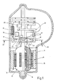
- electric drive unit for a windshield wiper in motor vehicles as an embodiment of a general vehicle unit has a motor housing 9 and an attached thereto two-piece gear housing 10, which consists of a Housing base and a housing cover, not shown here consists.
- a commutator motor 11 with stator 12 and rotor 13 is accommodated, whose rotor 13 supporting the elongated rotor shaft 14 projects as a transmission drive shaft of a transmission, not shown here in the gear housing 10.
- a rotor winding 15 accommodated in the rotor 13 is connected in an electrically conductive manner to the commutator bars of a commutator 16 which is seated in a rotationally fixed manner on the rotor shaft 14.
- On the circumference of the commutator 16 are carbon brushes 24 of three commutator brushes 17 (FIG. Fig. 2 ) Pressed with radial contact force, which are connected to a connector, not shown here.
- the drive unit further includes electrical components of an engine electronics, such as a Entstördrossl 18, a suppression capacitor 19, a diode 20, a thermal switch 21 and possibly not shown here resistors. All of these electrical components 18 - 21 are mounted on a stamped grid 22 made of electrically conductive material, which produces the electrical connections between the individual components and the commutator motor 11 and the commutator 17.
- the punched grid 22, also called lead frame, is integrated in the gear housing 10 and inserted in the embodiment in the housing cover and secured by ultrasonic welding or hot caulking provided for this purpose position pin on the housing cover.
- the stamped grid 22 can also be firmly connected to the existing also made of plastic housing base in the same way.
- the electrical and mechanical connection of the components 18-21 with the stamped grid 22 is performed by Welding the on the components 18 - 21 projecting legs on the metal webs of the lead frame 22, which is possible for example by means of laser welding.
- the commutator brushes 17 are formed as so-called.
- Hammer brushes in each of which a carbon brush 24 is held by a spring lever or support plate 23, which simultaneously applies the radial contact force for the carbon brush 24 to the commutator 16.
- Each support plate 23 is bent out of the stamped grid 22 in one piece, and the carbon brushes 24 are inserted from the side facing away from the commutator 16 back of the support plates 23 forth in corresponding recesses in the support plates 23 and fixed axially non-displaceable example by means not shown tabs.
- these joining aids 25 slide over the commutator 16 and thus facilitate the sliding of the commutator 17.
- the drive unit designed for a windshield wiper also has a limit switch for switching off the commutator motor 11 in the so-called parking position of the windscreen wiper.
- the one not shown here Limit switch is realized by means of a sliding contact, which interrupts the power supply to the commutator motor in the parking position of the windshield wiper.
- the cooperating with the sliding contact sliding contact spring is then also bent out of the stamped grid 22 in one piece.
Abstract
Description
- Die Erfindung geht aus von einer elektrischen Antriebseinheit für Fahrzeugaggregate, wie Fensterheber, Scheibenwischer od.dgl., der im Oberbegriff des Anspruchs 1 definierten Gattung.
- Eine bekannte elektrische Antriebseinheit für Fensterheber in Kraftfahrzeugen (
DE 90 13 006 U1 ) weist ein an das kommutatorseitige Ende des Kommutatormotors sich anschließendes Getriebegehäuse auf, in das die verlängerte Motorwelle als Getriebeantriebswelle (Schneckenwelle) hineinragt. In einem Elektronikgehäuse ist eine mit einem äußeren Anschlußstecker und Kommutatorbürsten sowie mit Bauelementen einer Motorelektronik elektrisch verbundene Leiterplatte angeordnet. Die Leiterplatte weist ein einstückiges Aufnahmeteil für die Bürstenhalterung und ein einstückiges Aufnahmeteil für den Anschlußstecker auf. Die elektrischen Anschlüsse der Bauelemente, der Bürsten und der Anschlußstecker sind mit den Leiterbahnen der Leiterplatte kontaktiert. Die Bürsten sind diametral am Kommutator angeordnet und jeweils in einem in der Bürstenhalterung ausgebildeten Köcher radial verschieblich gehalten. Das Elektronikgehäuse ist Bestandteil des Getriebegehäuses und durch einen mit dem Getriebegehäusedeckel einstückigen Elektronikgehäusedeckel verschlossen. - Aus der
DE 44 30 798 A1 ist ein Stanzgitter aus Metallstreifen bekannt, die als Leiterbahnen zur Verbindung von Bauelementen dienen. Die Bauelemente sind auf dem Stanzgitter aufgebracht und ihre Anschlußbeinchen an das Stanzgitter angeschweißt oder angelötet. Als Beispiel für mögliche Bauelemente sind integrierte Schaltungen, Sensoren, Widerstände, Kondensatoren etc., angegeben. Das Stanzgitter mit darauf angebrachten Bauelementen ist mit Kunststoff umspritzt. - Aus der
JP 60-131058 - Die erfindungsgemäße elektrische Antriebseinheit für Fahrzeugaggregate mit den Merkmalen des Anspruchs 1 hat den Vorteil, daß alle elektrischen Bauelemente und stromführenden Verbindungen auf einem pro Motortyp standardisierten Stanzgitter konzentriert sind, das ein gutes Handling gewährleistet und definierte Schnittstellen zum Grundstecker besitzt. Die als Hammerbürsten ausgeführten Kommutatorbürsten sind einstückiger Bestandteil des Stanzgitters und müssen nicht gesondert montiert und verdrahtet werden. Der Montageaufwand für die Bürstenmontage entfällt. Die Trägerbleche der Hammerbürsten stellen gleichzeitig die Bürstenandruckkräfte am Kommutator zur Verfügung. Die Zuführung der Schleifkohle erfolgt von der vom Kommutator abgekehrten Rückseite der Trägerbleche her. Das vom Stanzgitter mit Bauelementen und Kommutatorbürsten gebildete Einheitsteil kann automatisch gefertigt, gut bestückt, automatisch geschweißt und leicht montiert werden.
- Die Erfindung ist anhand eines in der Zeichnung dargestellten Ausführungsbeispiels in der nachfolgenden Beschreibung näher erläutert. Es zeigen jeweils in schematischer Darstellung:
- Fig. 1
- einen Längsschnitt einer elektrischen Antriebseinheit für eine Scheibenwischer in Kraftfahrzeugen,
- Fig. 2
- einen Schnitt längs der Linie II-II in
Fig. 1 . - Die in
Fig. 1 im Längsschnitt dargestellte elektrische Antriebseinheit für einen Scheibenwischer in Kraftfahrzeugen als Ausführungsbeispiel für ein allgemeines Fahrzeugaggregat weist ein Motorgehäuse 9 und ein daran angesetztes zweiteiliges Getriebegehäuse 10 auf, das aus einem Gehäuseunterteil und einem hier nicht dargestellten Gehäusedeckel besteht. In dem Motorgehäuse 9 ist ein Kommutatormotor 11 mit Stator 12 und Rotor 13 aufgenommen, dessen den Rotor 13 tragende verlängerte Rotorwelle 14 als Getriebeantriebswelle eines hier nicht dargestellten Getriebes in das Getriebegehäuse 10 hineinragt. Eine im Rotor 13 aufgenommene Rotorwicklung 15 ist mit den Kommutatorlamellen eines drehfest auf der Rotorwelle 14 sitzenden Kommutators 16 elektrisch leitend verbunden. Auf dem Umfang des Kommutators 16 sind Schleifkohlen 24 dreier Kommutatorbürsten 17 (Fig. 2 ) mit radialer Anpreßkraft aufgedrückt, die mit einem hier nicht dargestellten Anschlußstecker verbunden sind. - Zur Antriebseinheit gehören weiterhin elektrische Bauteile einer Motorelektronik, wie eine Entstördrossl 18, ein Entstörkondensator 19, eine Diode 20, ein Thermoschalter 21 sowie ggf. hier nicht dargestellte Widerstände. Alle diese elektrischen Bauteile 18 - 21 sind auf einem Stanzgitter 22 aus elektrisch leitendem Material befestigt, das die elektrischen Verbindungen zwischen den einzelnen Bauteilen und dem Kommutatormotor 11 bzw. den Kommutatorbürsten 17 herstellt. Das Stanzgitter 22, auch lead frame genannt, ist in dem Getriebegehäuse 10 integriert und im Ausführungsbeispiel in den Gehäusedeckel eingelegt und durch Ultraschallschweißen oder Warmverstemmung von hierfür vorgesehene Positionszapfen am Gehäusedeckel befestigt. Das Stanzgitter 22 kann auch in gleicher Weise mit dem ebenfalls aus Kunststoff bestehenden Gehäuseunterteil fest verbunden werden. Die elektrische und mechanische Verbindung der Bauteile 18 - 21 mit dem Stanzgitter 22 erfolgt durch Aufschweißen der an den Bauteilen 18 - 21 vorstehenden Beinchen auf die Metallstege des Stanzgitters 22, was z.B. mittels Laserschweißen möglich ist.
- Wie insbesondere aus der Schnittdarstellung in
Fig. 2 zu erkennen ist, sind die Kommutatorbürsten 17 als sog. Hammerbürsten ausgebildet, bei denen jeweils eine Schleifkohle 24 von einem Federhebel oder Trägerblech 23 gehalten wird, das gleichzeitig die radiale Anpreßkraft für die Schleifkohle 24 an den Kommutator 16 aufbringt. Jedes Trägerblech 23 ist dabei einstückig aus dem Stanzgitter 22 herausgebogen, und die Schleifkohlen 24 sind von der von dem Kommutator 16 abgekehrten Rückseite der Trägerbleche 23 her in entsprechende Aussparungen in den Trägerblechen 23 eingesetzt und z.B. mittels nicht dargestellter Laschen axial unverschieblich festgelegt. Die insgesamt drei Kommutatorbürsten 17, die alle in gleicher Weise als Hammerbürsten ausgebildet sind, ermöglichen den Betrieb des Kommutators 11 in zwei Drehzahlstufen. Zur Erleichterung der Montage ist an den freien Enden der Trägerbleche 23 der beiden einander diametral gegenüberliegenden Kommutatorbürsten 17 jeweils eine Fügungshilfe 25 in Form einer zum Kommutator 16 hin vorspringenden abgewinkelten Führungsnase ausgebildet. Beim Aufsetzen des Gehäusedeckels gleiten diese Fügungshilfen 25 über den Kommutator 16 und erleichtern somit das Aufschieben der Kommutatorbürsten 17. - In der Regel weist die für einen Scheibenwischer konzipierte Antriebseinheit noch einen Endlagenschalter zum Abschalten des Kommutatormotors 11 in der sog. Parklage des Scheibenwischers auf. Der hier nicht dargestellte Endlagenschalter wird mittels eines Schleifkontakts realisiert, der in der Parklage des Scheibenwischers die Stromzufuhr zu dem Kommutatormotor unterbricht. Die mit dem Schleifkontakt zusammenwirkende Schleifkontaktfeder wird dann ebenfalls einstückig aus dem Stanzgitter 22 herausgebogen.
Claims (5)
- Elektrische Antriebseinheit für Fahrzeugaggregate mit einem einen Kommutator (16) und mindestens zwei als Hammerbürsten ausgebildete Kommutatorbürsten (17) aufweisenden Kommutatormotor (11) und mit elektrischen Bauteilen (18 - 21) einer Motorelektronik, wobei
die elektrischen Bauteile (18 - 21) auf einem die elektrische Verbindung zwischen den Bauteilen (18 - 21) und dem Kommutatormotor (11) herstellenden Stanzgitter (22) befestigt sind, und dass die Hammerbürsten Trägerbleche (23) aufweisen, die aus dem Stanzgitter (22) einstückig herausgebogen sind, dadurch gekennzeichnet, dass die Antriebseinheit ferner ein der Rotorwelle (14) des Kommutatormotors (11) nachgeordnetes, in einem Getriebegehäuse (10) aufgenommenes Getriebe aufweist,
und das mit den Bauelementen (18 - 21) bestückte Stanzgitter (22) in dem Getriebegehäuse (10) integriert ist. - Antriebseinheit nach Anspruch 1, dadurch gekennzeichnet, daß das aus Kunststoff gefertigte Getriebegehäuse (10) zweiteilig ist und aus einem Gehäuseunterteil und einem Gehäusedeckel besteht und daß das Stanzgitter (22) in dem Gehäuseunterteil oder dem Gehäusedeckel eingelegt und mit diesem fest verbunden ist.
- Antriebseinheit nach Anspruch 2, dadurch gekennzeichnet, daß die Verbindung von Stanzgitter (22) und Gehäuseunterteil bzw. Gehäusedeckel durch Ultraschallschweißen oder Warmverstemmung von am Getriebegehäuse (10) angeformten Positionszapfen vorgenommen ist.
- Antriebseinheit nach einem der Ansprüche 1 - 3, dadurch gekennzeichnet, daß an den Trägerblechen (23) der Hammerbürsten jeweils eine Fügungshilfe (25) für das Aufschieben der Hammerbürsten (17) auf den Kommutator (16) ausgebildet ist.
- Antriebseinheit nach einem der Ansprüche 1 - 4 mit einem Endlagenschalter zum Abschalten des Kommutatormotors (11) in einer definierten Endlage des Fahrzeugaggregats, dadurch gekennzeichnet, daß der Endlagenschalter eine Schleifkontaktfeder aufweist, die aus dem Stanzgitter (22) einstückig herausgebogen ist.
Applications Claiming Priority (3)
| Application Number | Priority Date | Filing Date | Title |
|---|---|---|---|
| DE19858231 | 1998-12-17 | ||
| DE19858231A DE19858231A1 (de) | 1998-12-17 | 1998-12-17 | Elektrische Antriebseinheit für Fahrzeugaggregate |
| PCT/DE1999/001873 WO2000036728A1 (de) | 1998-12-17 | 1999-06-26 | Leiterbahnen mit kommutatorenbürsten für eine elektrische antriebseinheit für fahrzeugaggregate |
Publications (2)
| Publication Number | Publication Date |
|---|---|
| EP1055277A1 EP1055277A1 (de) | 2000-11-29 |
| EP1055277B1 true EP1055277B1 (de) | 2012-08-15 |
Family
ID=7891403
Family Applications (1)
| Application Number | Title | Priority Date | Filing Date |
|---|---|---|---|
| EP99941395A Expired - Lifetime EP1055277B1 (de) | 1998-12-17 | 1999-06-26 | Leiterbahnen mit Kommutatorbürsten für eine elektrische Antriebseinheit für Fahrzeugaggregate |
Country Status (7)
| Country | Link |
|---|---|
| US (1) | US6376962B1 (de) |
| EP (1) | EP1055277B1 (de) |
| JP (1) | JP4335461B2 (de) |
| KR (1) | KR100629100B1 (de) |
| BR (1) | BR9907958A (de) |
| DE (1) | DE19858231A1 (de) |
| WO (1) | WO2000036728A1 (de) |
Families Citing this family (7)
| Publication number | Priority date | Publication date | Assignee | Title |
|---|---|---|---|---|
| DE10352234A1 (de) * | 2003-11-08 | 2005-06-09 | Robert Bosch Gmbh | Elektromotor, insbesondere zum Verstellen beweglicher Teile im Kraftfahrzeug |
| EP1619774A1 (de) * | 2004-07-23 | 2006-01-25 | Siemens Aktiengesellschaft | Bürstensystem für einen Kraftfahrzeug-Stellantrieb |
| US7135801B2 (en) * | 2004-08-24 | 2006-11-14 | Asmo Co., Ltd. | Motor apparatus having rotational position detector |
| DE102005060863B3 (de) * | 2005-12-20 | 2007-02-08 | Robert Bosch Gmbh | Scheibenwischvorrichtung |
| GB0809764D0 (en) * | 2008-05-30 | 2008-07-09 | Johnson Electric Sa | Electric motor |
| US9277787B2 (en) | 2013-03-15 | 2016-03-08 | Nike, Inc. | Microwave bonding of EVA and rubber items |
| US9955536B2 (en) | 2013-03-15 | 2018-04-24 | Nike, Inc. | Customized microwave energy distribution utilizing slotted cage |
Family Cites Families (15)
| Publication number | Priority date | Publication date | Assignee | Title |
|---|---|---|---|---|
| DE4430798A1 (de) * | 1994-08-30 | 1996-03-07 | Siemens Ag | Stanzgitter zur Verbindung von elektrischen Bauelementen |
| FR2104345A7 (de) * | 1970-08-19 | 1972-04-14 | Nippon Denso Co | |
| US4396850A (en) * | 1982-01-12 | 1983-08-02 | The Singer Company | Brush board assembly for dynamoelectric machine with flat end commutator |
| US4404488A (en) * | 1982-01-12 | 1983-09-13 | The Singer Company | Brush board assembly for dynamoelectric machine |
| DE3235622A1 (de) * | 1982-09-25 | 1984-03-29 | SWF-Spezialfabrik für Autozubehör Gustav Rau GmbH, 7120 Bietigheim-Bissingen | Elektrischer kleinmotor, insbesondere fuer scheibenwischanlagen in kraftfahrzeugen |
| JPS60131058A (ja) * | 1983-12-20 | 1985-07-12 | Matsushita Electric Works Ltd | モ−タ |
| DE3538940A1 (de) * | 1985-10-31 | 1987-05-07 | Black & Decker Inc | Verdrahtungsanordnung fuer den motor eines elektrowerkzeugs |
| DE9013006U1 (de) * | 1990-09-12 | 1991-07-04 | Siemens Ag, 8000 Muenchen, De | |
| DE9209448U1 (de) * | 1992-07-14 | 1993-11-18 | Bosch Gmbh Robert | Vorrichtung zur Halterung von Bauelementen |
| DE4226553A1 (de) * | 1992-08-11 | 1994-02-17 | Teves Gmbh Alfred | Bürstenhalter für Elektromotoren |
| GB9316643D0 (en) * | 1993-08-11 | 1993-09-29 | Johnson Electric Sa | Two-part end cap assembly |
| DE4412319A1 (de) * | 1994-04-11 | 1995-10-12 | Teves Gmbh Alfred | Stromzuführungsanordnung für einen Elektromotor mit vier Bürsten |
| DE4430953A1 (de) * | 1994-08-31 | 1996-03-07 | Teves Gmbh Alfred | Kontaktplatte |
| GB9520389D0 (en) * | 1995-10-06 | 1995-12-06 | Johnson Electric Sa | Brush gear for an electronic motor |
| US6051899A (en) * | 1996-06-15 | 2000-04-18 | Itt Manufacturing Enterprises, Inc. | Drive mechanism |
-
1998
- 1998-12-17 DE DE19858231A patent/DE19858231A1/de not_active Withdrawn
-
1999
- 1999-06-26 BR BR9907958-5A patent/BR9907958A/pt not_active IP Right Cessation
- 1999-06-26 KR KR1020007008950A patent/KR100629100B1/ko not_active IP Right Cessation
- 1999-06-26 JP JP2000588878A patent/JP4335461B2/ja not_active Expired - Fee Related
- 1999-06-26 EP EP99941395A patent/EP1055277B1/de not_active Expired - Lifetime
- 1999-06-26 US US09/601,995 patent/US6376962B1/en not_active Expired - Fee Related
- 1999-06-26 WO PCT/DE1999/001873 patent/WO2000036728A1/de active IP Right Grant
Also Published As
| Publication number | Publication date |
|---|---|
| EP1055277A1 (de) | 2000-11-29 |
| JP2002533049A (ja) | 2002-10-02 |
| KR20010024916A (ko) | 2001-03-26 |
| US6376962B1 (en) | 2002-04-23 |
| JP4335461B2 (ja) | 2009-09-30 |
| KR100629100B1 (ko) | 2006-09-28 |
| DE19858231A1 (de) | 2000-06-29 |
| WO2000036728A1 (de) | 2000-06-22 |
| BR9907958A (pt) | 2000-10-24 |
Similar Documents
| Publication | Publication Date | Title |
|---|---|---|
| EP1057239B1 (de) | Elektrischer getriebemotor für fahrzeugaggregate | |
| EP0993696B1 (de) | Antriebsvorrichtung, insbesondere zum verstellen eines schiebedachs eines fahrzeugs | |
| WO2000038300A1 (de) | Stellantrieb mit einem elektromotor und mit einer steuerelektronik | |
| EP0687593B2 (de) | Elektrische Einrichtung für Kraftfahrzeuge, insbesondere Lenkstockschalter dafür | |
| WO1998040751A1 (de) | Motor mit drehzahlabgriff über einen hall-sensor | |
| WO2013164156A2 (de) | Gleichstrommotor zum antrieb von aggregaten eines kraftfahrzeugs | |
| DE102005055740A1 (de) | Elektrische Maschine mit Kontaktpads aufweisender Leiterplatte | |
| DE102012213234A1 (de) | Verstellantrieb | |
| EP1055277B1 (de) | Leiterbahnen mit Kommutatorbürsten für eine elektrische Antriebseinheit für Fahrzeugaggregate | |
| WO2014173577A2 (de) | Schaltungsträger, anordnung mit einem schaltungsträger und verfahren zum herstellen einer elektrischen kontaktierung | |
| WO2007039341A1 (de) | Elektromotor mit hammerbürsten | |
| EP2665162B1 (de) | Gleichstrommotor zum Antrieb von Aggregaten eines Kraftfahrzeugs | |
| WO2006117265A1 (de) | Verbindungsvorrichtung | |
| EP1402615B1 (de) | Gehäuseteil für einen elektrischen verstellantrieb | |
| DE102004036419B4 (de) | Elektromotorischer Hilfsantrieb | |
| DE102015122095A1 (de) | Anschlusseinheit für einen Wischermotor für Scheibenwischanlagen und Wischermotor | |
| WO2008046731A1 (de) | Trägerteil für die bürsten eines kommutatormotors | |
| DE102009029492B4 (de) | Antriebsvorrichtung für Scheibenwischer mit einer Positionsermittlungseinrichtung | |
| WO2018091242A1 (de) | Elektrische maschine | |
| WO2001057990A1 (de) | Stanzgitter mit integriertem hall-sensor für drehzahlabgriff | |
| WO2005046025A1 (de) | Elektromotor, insbesondere zum verstellen beweglicher teile im kraftfahrzeug | |
| DE102019210843A1 (de) | Elektrische Maschine, insbesondere zum Verstellen beweglicher Teile in einem Kraftfahrzeug | |
| DE102022110700A1 (de) | Getriebe und Scheibenwischermotor mit einem Getriebe | |
| DE102004034029A1 (de) | Elektrische Antriebseinheit mit mindestens zwei elektrischen Bauteilträgern, sowie Verfahren zum Herstellen einer solchen | |
| DE102017121217A1 (de) | Bürstenloser Elektromotor und Verfahren zu dessen Montage |
Legal Events
| Date | Code | Title | Description |
|---|---|---|---|
| PUAI | Public reference made under article 153(3) epc to a published international application that has entered the european phase |
Free format text: ORIGINAL CODE: 0009012 |
|
| AK | Designated contracting states |
Kind code of ref document: A1 Designated state(s): DE ES FR GB IT |
|
| 17P | Request for examination filed |
Effective date: 20001222 |
|
| 17Q | First examination report despatched |
Effective date: 20061121 |
|
| GRAJ | Information related to disapproval of communication of intention to grant by the applicant or resumption of examination proceedings by the epo deleted |
Free format text: ORIGINAL CODE: EPIDOSDIGR1 |
|
| GRAP | Despatch of communication of intention to grant a patent |
Free format text: ORIGINAL CODE: EPIDOSNIGR1 |
|
| GRAC | Information related to communication of intention to grant a patent modified |
Free format text: ORIGINAL CODE: EPIDOSCIGR1 |
|
| GRAP | Despatch of communication of intention to grant a patent |
Free format text: ORIGINAL CODE: EPIDOSNIGR1 |
|
| RIC1 | Information provided on ipc code assigned before grant |
Ipc: H01R 39/39 20060101ALI20120413BHEP Ipc: H02K 5/14 20060101AFI20120413BHEP |
|
| GRAS | Grant fee paid |
Free format text: ORIGINAL CODE: EPIDOSNIGR3 |
|
| GRAA | (expected) grant |
Free format text: ORIGINAL CODE: 0009210 |
|
| AK | Designated contracting states |
Kind code of ref document: B1 Designated state(s): DE ES FR GB IT |
|
| REG | Reference to a national code |
Ref country code: GB Ref legal event code: FG4D Free format text: NOT ENGLISH |
|
| REG | Reference to a national code |
Ref country code: DE Ref legal event code: R096 Ref document number: 59915345 Country of ref document: DE Effective date: 20121011 |
|
| PG25 | Lapsed in a contracting state [announced via postgrant information from national office to epo] |
Ref country code: ES Free format text: LAPSE BECAUSE OF FAILURE TO SUBMIT A TRANSLATION OF THE DESCRIPTION OR TO PAY THE FEE WITHIN THE PRESCRIBED TIME-LIMIT Effective date: 20121126 |
|
| PG25 | Lapsed in a contracting state [announced via postgrant information from national office to epo] |
Ref country code: IT Free format text: LAPSE BECAUSE OF FAILURE TO SUBMIT A TRANSLATION OF THE DESCRIPTION OR TO PAY THE FEE WITHIN THE PRESCRIBED TIME-LIMIT Effective date: 20120815 |
|
| PLBE | No opposition filed within time limit |
Free format text: ORIGINAL CODE: 0009261 |
|
| STAA | Information on the status of an ep patent application or granted ep patent |
Free format text: STATUS: NO OPPOSITION FILED WITHIN TIME LIMIT |
|
| 26N | No opposition filed |
Effective date: 20130516 |
|
| REG | Reference to a national code |
Ref country code: DE Ref legal event code: R097 Ref document number: 59915345 Country of ref document: DE Effective date: 20130516 |
|
| PGFP | Annual fee paid to national office [announced via postgrant information from national office to epo] |
Ref country code: DE Payment date: 20130828 Year of fee payment: 15 |
|
| GBPC | Gb: european patent ceased through non-payment of renewal fee |
Effective date: 20130626 |
|
| REG | Reference to a national code |
Ref country code: FR Ref legal event code: ST Effective date: 20140228 |
|
| PG25 | Lapsed in a contracting state [announced via postgrant information from national office to epo] |
Ref country code: GB Free format text: LAPSE BECAUSE OF NON-PAYMENT OF DUE FEES Effective date: 20130626 |
|
| PG25 | Lapsed in a contracting state [announced via postgrant information from national office to epo] |
Ref country code: FR Free format text: LAPSE BECAUSE OF NON-PAYMENT OF DUE FEES Effective date: 20130701 |
|
| REG | Reference to a national code |
Ref country code: DE Ref legal event code: R119 Ref document number: 59915345 Country of ref document: DE |
|
| REG | Reference to a national code |
Ref country code: DE Ref legal event code: R119 Ref document number: 59915345 Country of ref document: DE Effective date: 20150101 |
|
| PG25 | Lapsed in a contracting state [announced via postgrant information from national office to epo] |
Ref country code: DE Free format text: LAPSE BECAUSE OF NON-PAYMENT OF DUE FEES Effective date: 20150101 |