EP1054067A2 - Verfahren zum Verschliessen und Öffnen eines Stichloches eines metallurgischen Gefässes - Google Patents
Verfahren zum Verschliessen und Öffnen eines Stichloches eines metallurgischen Gefässes Download PDFInfo
- Publication number
- EP1054067A2 EP1054067A2 EP00108441A EP00108441A EP1054067A2 EP 1054067 A2 EP1054067 A2 EP 1054067A2 EP 00108441 A EP00108441 A EP 00108441A EP 00108441 A EP00108441 A EP 00108441A EP 1054067 A2 EP1054067 A2 EP 1054067A2
- Authority
- EP
- European Patent Office
- Prior art keywords
- tap hole
- movement
- closure body
- longitudinal axis
- approximately
- Prior art date
- Legal status (The legal status is an assumption and is not a legal conclusion. Google has not performed a legal analysis and makes no representation as to the accuracy of the status listed.)
- Granted
Links
Images




Classifications
-
- F—MECHANICAL ENGINEERING; LIGHTING; HEATING; WEAPONS; BLASTING
- F27—FURNACES; KILNS; OVENS; RETORTS
- F27D—DETAILS OR ACCESSORIES OF FURNACES, KILNS, OVENS OR RETORTS, IN SO FAR AS THEY ARE OF KINDS OCCURRING IN MORE THAN ONE KIND OF FURNACE
- F27D3/00—Charging; Discharging; Manipulation of charge
- F27D3/15—Tapping equipment; Equipment for removing or retaining slag
- F27D3/1509—Tapping equipment
-
- B—PERFORMING OPERATIONS; TRANSPORTING
- B22—CASTING; POWDER METALLURGY
- B22D—CASTING OF METALS; CASTING OF OTHER SUBSTANCES BY THE SAME PROCESSES OR DEVICES
- B22D41/00—Casting melt-holding vessels, e.g. ladles, tundishes, cups or the like
- B22D41/14—Closures
-
- C—CHEMISTRY; METALLURGY
- C21—METALLURGY OF IRON
- C21B—MANUFACTURE OF IRON OR STEEL
- C21B7/00—Blast furnaces
- C21B7/12—Opening or sealing the tap holes
-
- C—CHEMISTRY; METALLURGY
- C21—METALLURGY OF IRON
- C21C—PROCESSING OF PIG-IRON, e.g. REFINING, MANUFACTURE OF WROUGHT-IRON OR STEEL; TREATMENT IN MOLTEN STATE OF FERROUS ALLOYS
- C21C5/00—Manufacture of carbon-steel, e.g. plain mild steel, medium carbon steel or cast steel or stainless steel
- C21C5/28—Manufacture of steel in the converter
- C21C5/42—Constructional features of converters
- C21C5/46—Details or accessories
- C21C5/4653—Tapholes; Opening or plugging thereof
-
- F—MECHANICAL ENGINEERING; LIGHTING; HEATING; WEAPONS; BLASTING
- F27—FURNACES; KILNS; OVENS; RETORTS
- F27D—DETAILS OR ACCESSORIES OF FURNACES, KILNS, OVENS OR RETORTS, IN SO FAR AS THEY ARE OF KINDS OCCURRING IN MORE THAN ONE KIND OF FURNACE
- F27D3/00—Charging; Discharging; Manipulation of charge
- F27D3/15—Tapping equipment; Equipment for removing or retaining slag
- F27D3/1545—Equipment for removing or retaining slag
- F27D3/159—Equipment for removing or retaining slag for retaining slag during the pouring of the metal or retaining metal during the pouring of the slag
-
- F—MECHANICAL ENGINEERING; LIGHTING; HEATING; WEAPONS; BLASTING
- F27—FURNACES; KILNS; OVENS; RETORTS
- F27D—DETAILS OR ACCESSORIES OF FURNACES, KILNS, OVENS OR RETORTS, IN SO FAR AS THEY ARE OF KINDS OCCURRING IN MORE THAN ONE KIND OF FURNACE
- F27D3/00—Charging; Discharging; Manipulation of charge
- F27D3/16—Introducing a fluid jet or current into the charge
Definitions
- the invention relates to a method for closing and opening a tap hole metallurgical vessel, in particular a steel plant converter, wherein a Closure body leaving an annular gap between the closure body and the Wall of the tap hole from a waiting position into one that covers the tap hole Closing position and return can be brought, and being, at least in the Closed position, a pressurized gas in the tap hole against the outflow direction in the metallurgical vessel contained melt is introduced, as well as a facility for Execution of the procedure.
- a method of this type and an apparatus for carrying out the method are known DE 32 08 490 C and from AT 350 090 B known.
- Oxygen-blowing steelwork converters have for the purpose of parting off the steel bath its own tap hole, which is located far below the mouth of the converter.
- tap hole which is located far below the mouth of the converter.
- Amount of slag - called moving slag - is carried away, in the end, if the converter is empty of steel, the tail slag until the converter is tipped back.
- Oxidation reactions make unwanted pig iron into steel accompanying elements of the iron smelter bound to oxygen and the formed oxides released in gaseous form or transferred into the slag.
- After freshening up elements often have to be added to the steel for deoxidation and alloying purposes that have a higher affinity for oxygen than that in the slag tied unwanted accompanying elements.
- the consequence of this is that such Alloy elements reduce the unwanted accompanying elements from the slag can, slagging themselves.
- Fresh slag can also be very aggressive compared to the refractory material of the melting pot and ladle. Out For reasons of quality and for reasons of economy, one strives to: Tapping and alloying a melt in the pan, as far as possible with the slag to prevent.
- Opening and closing the tap hole with one of the above Facilities has proven itself in practice, but the following disadvantage occurs:
- the transition from the slag outlet to the steel outlet is by means of of a ratio pyrometer observed which occurs during the transition from steel to slag or Slag to steel gives an impulse for the swinging in and out of the Closure body is used to close or open the tap hole.
- the problem is the uniqueness of the signal. If with a compressed gas, e.g. With Nitrogen, which is blown to retain slag, is blown out of the tap hole itself. If steel also comes to the inside opening of the tap hole, it becomes heavier is to enter the tap hole. It is initially mixed with slag and it forms extremely turbulent condition.
- the jet itself is caused by the pressurized gas initially held back. As a result, it comes from a certain bath level above the tap hole suddenly due to the increasing pressure of the steel bath This increasingly unstable state topples over until there is a surge of steel fluid pours into the tap hole.
- the signal receiver will then respond, but it is not closed prevent part of this amount from pouring out before the closure body front tap hole is removed.
- Steel is already flowing before the tap hole is fully opened through the tap hole on the closure body.
- the amount of steel flowing out is in of the order of 120 to 250 kg steel and depends on the taphole condition. This Quantity pours over the closure device, which places an extraordinary burden on it and is bearded.
- the invention aims to avoid the disadvantages and difficulties of the prior art Technology and set themselves the task, a method and an implementation facility to create the process by which a danger of becoming essential is reduced and which is a racking with significantly reduced slag discharge enable.
- This object is achieved according to the invention in a method of the type described in the introduction solved in that the closure body with lying in different areas Movement directions from the waiting position to the closed position and back is moved.
- the closure body is moved from the waiting position into the Closing position initially in a main movement component approximately transverse to Longitudinal axis of the tap hole movement direction and just before reaching the Closed position in a main movement component approximately in the direction of the longitudinal axis the direction of movement and when moving from the Closing position in the waiting position initially via a short path in one Direction of movement with a main movement component approximately in the direction of Longitudinal axis of the tap hole and then over a longer path in one Direction of movement with a main movement component approximately transverse to the direction of Longitudinal axis of the tap hole is moved.
- This enables the movement of the Closure body in the area of the jet emerging from the tap hole on the unconditional reduce necessary measure.
- a compressed gas jet is placed in the tap hole
- the closure body in one plane moves in which the longitudinal axis of the tap hole lies, whereby the closure body with its compressed gas outlet comes to lie within the tap hole.
- the movement with the main movement component is expediently approximately transverse to Longitudinal axis of the tap hole over a much longer path than that Movement with the main movement component in the direction of the longitudinal axis of the Tap hole, preferably over a path at least five to ten times as long.
- a device for closing a tap hole of a metallurgical vessel, in particular a steelworks converter, a closure body leaving a Annular gap between the closure body and the wall of the tap hole from one Waiting position in a closing position covering the taphole and back by means of a Movement device can be brought, and wherein the closure body with at least one pressure gas outlet connected to a gas supply line at its closed position the taphole facing side is characterized in that the Closure body with the movement device for moving the closure body the waiting position in the closed position first in a direction of movement with a Main motion component approximately transverse to the longitudinal axis of the tap hole and then in the closed position with a main movement component approximately in the direction of the longitudinal axis the tap hole is movable.
- two movement devices are provided, one of which is a movement of the closure body with the main movement component approximately transverse to the direction of Longitudinal axis of the tap hole and the further movement means a movement of the Closure body with a main movement component approximately in the direction of the longitudinal axis of the tap hole, two advantageous as movement devices Swiveling devices are provided, the closure body being mounted on an arm which is pivotable in two planes approximately at right angles to each other.
- a device has been found to be particularly robust which is characterized in that the movement devices of pressure medium cylinders, each via a lever system attack the arm carrying the closure body, are formed.
- a preferred embodiment is characterized in that the closure body an arm projecting from a pivot axis is arranged, which pivot axis an approximately perpendicular to her pendulum shaft is pivotally mounted, the Pendulum shaft rotatable on a holding device arranged on the metallurgical vessel is mounted, the rotational movement of the pendulum shaft advantageously over approximately 40 to 60 °, and the pivoting movement extends about 5 to 15 ° about the pivot axis.
- a structurally simple solution is characterized in that the pressure medium cylinder to perform a rotation of the pendulum shaft via one on the pendulum shaft attacking lever and the pressure cylinder to carry out the pivoting movement about the pivot axis via a radially projecting spherical bearing at one end of an arm attacks an angle lever, the other arm carries the closure body.
- Fig. 1 illustrates the area in which when opening or closing a tap hole closure according to the prior art the tap hole body is in the immediate vicinity or within the tapping beam.
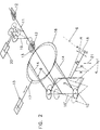
- Fig. 2 shows a schematic representation of a device of the type according to the invention in Diagonal tear;
- Fig. 3 illustrates a plan view of the tap hole in the direction of Longitudinal axis of the tap hole and shows the device according to the invention and the Closure body pivoted out laterally,
- Fig. 4 in a representation analogous to Fig. 3 Lock body swung in and approximately flush with the longitudinal axis of the tap hole.
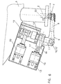
- the 5 and 6 each illustrate a side view approximately perpendicular to the longitudinal axis of the Taphole, etc. cut, once (Fig. 6) in the closed position and once (Fig. 5) short before.
- Fig. 7 shows the movement of the closure body in diagram form.
- Fig. 1 is a tapping beam 1, which emerges from the tap hole 2 of a pivotable and according to FIG. 1 converter pivoted in tapping position 3 (of which only the tap hole exhibiting area) emerges, shown.
- a schematically represented Lock body 4 which is attached to a pivot arm 5, is in one plane pivotable, which is placed through the longitudinal axis 6 of the tap hole 2.
- the Closure body 4 has on its side facing the tap hole 2 in the closed position II a compressed gas outlet 7, which to a flexible not shown in the drawing Compressed gas line is connected and through the compressed gas as a retention medium Tap hole 2 is inflatable.
- the activation of the compressed gas can already during the Swivel process, etc. from a point in time from which the closure body in is located near the tapping beam 1.
- the closure body 4 when pivoting in or out of the Waiting position 1 in the closed position II or vice versa from the closed position II in the Waiting position 1 over a swivel angle ⁇ of approximately 30 ° in the immediate heat-affected close range of the tapping beam 1 or in direct contact with the tapping beam 1.
- This configuration results in a long period of time in which the tapping beam 1 acts on the closure body 4, and there can be a bear do not avoid the same and the swivel arm 5.
- the closure body 4 is on an arm 8 a two-armed angle lever 9 attached, which forms a pivot axis 10 ' Pivot bearing 10 is pivotally mounted on a pendulum shaft 11.
- the pendulum shaft 11 is rotatable via bearing 12 on a holding device attached to the metallurgical vessel 3 13 hinged.
- the second arm 14 of the angle lever 9 is by means of a Pressure medium cylinder 15 designed movement device with respect to the pendulum shaft 11 pivotable, what by a pivot bearing 16 on which the piston 17 of the pressure cylinder 15 attacks, is realized.
- the angle ⁇ about which the angle lever 9 can be pivoted is relatively small; it is about 10 °.
- the direction of movement in which the closure body 4 is pivotable by means of the angle lever 9, has a main movement component 18 in Direction of the longitudinal axis 6 of the tap hole 2.
- the angle ⁇ around which the pendulum shaft 11 is pivotable is greater than the angle ⁇ by which the angle lever 9 can be pivoted. It extends over about 50 °.
- the closure body 4 which is in one plane is directed more or less perpendicular to the longitudinal axis 6 of the tap hole 2, pivoted become.
- the retention medium e.g. nitrogen
- the retention medium is advantageously applied radially via a rotary valve the pendulum axis 11 initiated.
- the nitrogen reaches a sliding surface in this wave and from this over the arm 8 to the closure body 4.
- the not shown The sliding surface creates the connection from the pendulum axis to the arm 8.
- the invention can also be implemented in other ways. For example, by the swiveling and rotating movements via link controls or Quadrangular movement devices can be realized.
- Fig. 7 shows that with the device according to the invention very short opening and closing Allow closing times that are of great metallurgical importance to be achieved.
- On the The ordinate is the swiveling or rotating movements of the pendulum shaft 11 and Angle lever 9 specified in degrees.
- the abscissa shows the times for the Rotation of the pendulum shaft 11 and pivoting of the angle lever 9 are required. From A to B the pendulum shaft 11 is rotated, from C to D the angle lever 9 is pivoted, etc. to close the tap hole 2. The closed position is from D to D ' adhered to. From D 'to C' the angle lever 9 is pivoted back, and from B 'to A 'turning back the pendulum shaft 11; both while opening the tap hole 2. Die Points A and A 'illustrate the waiting position I, points D and D' that Closed position II and B and B 'the intermediate position III of the closure body 4th
- the essence of the invention is the fact that when opening the tap hole 2 of Closure body 4 initially from the tap hole 2 in a first direction of movement a main movement component 18, which is approximately in the direction of the longitudinal axis 6 of the Stitch hole 2 is directed, is moved out until it is just below it, whereupon with a main movement component 21 approximately transversely to the longitudinal axis 6 of the tap hole 2 is moved away.
- a main movement component 18 which is approximately in the direction of the longitudinal axis 6 of the Stitch hole 2 is directed
- closure body 4th not only in one plane of movement, as is realized in the prior art, moved, that is pivoted about only in one plane through the longitudinal axis 6 of the Stitch hole 2 is placed, but a spatially combined movement in different Areas that do not necessarily have to be flat are completed.
Landscapes
- Engineering & Computer Science (AREA)
- Chemical & Material Sciences (AREA)
- Manufacturing & Machinery (AREA)
- Materials Engineering (AREA)
- Metallurgy (AREA)
- Organic Chemistry (AREA)
- Mechanical Engineering (AREA)
- General Engineering & Computer Science (AREA)
- Carbon Steel Or Casting Steel Manufacturing (AREA)
- Furnace Charging Or Discharging (AREA)
Abstract
Description
Claims (12)
- Verfahren zum Verschließen und Öffnen eines Stichloches (2) eines metallurgischen Gefäßes (3), insbesondere eines Stahlwerkskonverters, wobei ein Verschlußkörper (4) unter Freilassung eines Ringspaltes (23) zwischen dem Verschlußkörper (4) und der Wand (22) des Stichloches (2) aus einer Warteposition (I) in eine das Stichloch (2) verdeckende Schließposition (II) und retour gebracht werden kann, und wobei, zumindest in der Schließposition (II), ein Druckgas in das Stichloch (2) entgegen der Ausströmrichtung einer im metallurgischen Gefäß (3) enthaltenen Schmelze eingeleitet wird, dadurch gekennzeichnet, daß der Verschlußkörper (4) mit in unterschiedlichen Flächen liegenden Bewegungsrichtungen aus der Warteposition (I) in die Schließposition (II) und retour bewegt wird.
- Verfahren nach Anspruch 1, dadurch gekennzeichnet, daß der Verschlußkörper (4) beim Verbringen aus der Warteposition (I) in die Schließposition (II) zunächst in einer eine Hauptbewegungskomponente (21) etwa quer zur Längsachse (6) des Stichloches (2) aufweisenden Bewegungsrichtung und knapp vor Erreichen der Schließposition (II) in einer eine Hauptbewegungskomponente (18) etwa in Richtung der Längsachse (6) des Stichloches (2) aufweisenden Bewegungsrichtung und beim Bewegen aus der Schließposition (II) in die Warteposition (I) zunächst über einen kurzen Weg in einer Bewegungsrichtung mit einer Hauptbewegungskomponente (18) etwa in Richtung der Längsachse (6) des Stichloches (2) und anschließend über einen längeren Weg in einer Bewegungsrichtung mit einer Hauptbewegungskomponente (21) etwa quer zur Richtung der Längsachse (6) des Stichloches (2) bewegt wird.
- Verfahren nach Anspruch 2, dadurch gekennzeichnet, daß die Bewegungsrichtung mit einer Hauptbewegungskomponente (18) etwa in Richtung der Längsachse (6) des Stichloches (2) nur über eine sehr geringe Weglänge durchgeführt wird, insbesondere nur über eine Weglänge, ab der der Verschlußkörper (4) zur Gänze außerhalb des Stichloches (2) liegt.
- Verfahren nach Anspruch 2 oder 3, dadurch gekennzeichnet, daß die Bewegung mit der Hauptbewegungskomponente (21) etwa quer zur Längsachse (6) des Stichloches (2) über einen wesentlich längeren Weg durchgeführt wird als die Bewegung mit der Hauptbewegungskomponente (18) in Richtung der Längsachse (6) des Stichloches (2), vorzugsweise über einen mindestens fünf- bis zehnmal so langen Weg.
- Einrichtung zum Verschließen eines Stichloches (2) eines metallurgischen Gefäßes (3), insbesondere eines Stahlwerkskonverters, wobei ein Verschlußkörper (4) unter Freilassung eines Ringspaltes (23) zwischen dem Verschlußkörper (4) und der Wandung (22) des Stichloches (2) aus einer Warteposition (I) in eine das Stichloch (2) bedeckende Schließposition (II) und retour mittels einer Bewegungseinrichtung (14, 20) bringbar ist, und wobei der Verschlußkörper (4) mit mindestens einem an eine Gaszuführungsleitung angeschlossenen Druckgasauslaß (7) an seiner in Schließstellung (II) dem Stichloch (2) zugewendeten Seite versehen ist, dadurch gekennzeichnet, daß der Verschlußkörper (4) mit der Bewegungseinrichtung (14, 20) zum Verbringen des Verschlußkörpers (4) aus der Warteposition (I) in die Schließposition (II) zuerst in eine Bewegungsrichtung mit einer Hauptbewegungskomponente (21) etwa quer zur Längsachse (6) des Stichloches (2) und anschließend in die Schließposition (II) mit einer Hauptbewegungskomponente (18) etwa in Richtung der Längsachse (6) des Stichloches (2) bewegbar ist.
- Einrichtung nach Anspruch 5, dadurch gekennzeichnet, daß zwei Bewegungseinrichtungen (14, 20) vorgesehen sind, wovon eine (20) eine Bewegung des Verschlußkörpers (4) mit der Hauptbewegungskomponente (21) etwa quer zur Richtung der Längsachse (6) des Stichloches (2) und die weitere Bewegungseinrichtung (14) eine Bewegung des Verschlußkörpers (4) mit einer Hauptbewegungskomponente (18) etwa in Richtung der Längsachse (6) des Stichloches (2) ermöglicht.
- Einrichtung nach Anspruch 6, dadurch gekennzeichnet, daß als Bewegungseinrichtungen zwei Schwenkeinrichtungen (14, 9, 20, 19) vorgesehen sind, wobei der Verschlußkörper (4) an einem Arm (8) gelagert ist, der in zwei zueinander etwa im rechten Winkel stehende Ebenen schwenkbar ist.
- Einrichtung nach Anspruch 7, dadurch gekennzeichnet, daß die Bewegungseinrichtungen von Druckmittelzylindern (14, 20), die jeweils über ein Hebelsystem (9, 14, 8; 19) am den Verschlußkörper (4) tragenden Arm (8) angreifen, gebildet sind.
- Einrichtung nach Anspruch 6 oder 7, dadurch gekennzeichnet, daß der Verschlußkörper (4) an einem von einer Schwenkachse (10') auskragenden Arm (8) angeordnet ist, welche Schwenkachse (10) an einer etwa senkrecht zu ihr gerichteten Pendelwelle (11) schwenkbar gelagen ist, wobei die Pendelwelle (11) an einer am metallurgischen Gefäß (3) angeordneten Haltevorrichtung (13) drehbar gelagert ist.
- Einrichtung nach Anspruch 9, dadurch gekennzeichnet, daß die Drehbewegung der Pendelwelle (11) sich über etwa 40 bis 60°, und die Schwenkbewegung um die Schwenkachse (10') sich über 5 bis 15° erstreckt.
- Einrichtung nach Anspruch 9 oder 10, dadurch gekennzeichnet, daß der Druckmittelzylinder (20) zur Durchführung einer Drehung der Pendelwelle (11) über einen an der Pendelwelle (11) angreifenden Hebel (19) und der Druckmittelzylinder (14) zur Durchführung der Schwenkbewegung um die Schwenkachse (10') über ein radial auskragendes Gelenklager (16) an einem Ende eines Armes (14) eines Winkelhebels (9) angreift, dessen anderer Arm (8) den Verschlußkörper (4) trägt.
- Einrichtung nach einem oder mehreren der Ansprüche 8 bis 11, dadurch gekennzeichnet, daß die Druckmittelzylinder mit nur zwei Steuerleitungen aktivierbar sind.
Applications Claiming Priority (2)
| Application Number | Priority Date | Filing Date | Title |
|---|---|---|---|
| AT0090899A AT407399B (de) | 1999-05-21 | 1999-05-21 | Verfahren zum verschliessen und öffnen eines stichloches eines metallurgischen gefässes |
| AT90899 | 1999-05-21 |
Publications (3)
| Publication Number | Publication Date |
|---|---|
| EP1054067A2 true EP1054067A2 (de) | 2000-11-22 |
| EP1054067A3 EP1054067A3 (de) | 2001-03-21 |
| EP1054067B1 EP1054067B1 (de) | 2004-06-02 |
Family
ID=3502613
Family Applications (1)
| Application Number | Title | Priority Date | Filing Date |
|---|---|---|---|
| EP00108441A Expired - Lifetime EP1054067B1 (de) | 1999-05-21 | 2000-04-18 | Verfahren und Einrichtung zum Verschliessen und Öffnen eines Stichloches eines metallurgischen Gefässes |
Country Status (4)
| Country | Link |
|---|---|
| US (1) | US6379608B1 (de) |
| EP (1) | EP1054067B1 (de) |
| AT (1) | AT407399B (de) |
| DE (1) | DE50006657D1 (de) |
Cited By (2)
| Publication number | Priority date | Publication date | Assignee | Title |
|---|---|---|---|---|
| WO2020064691A1 (de) | 2018-09-25 | 2020-04-02 | Sms Group Gmbh | Schlackenstopper |
| CN117430119A (zh) * | 2023-12-20 | 2024-01-23 | 四川优赛思智能科技有限公司 | 一种具备自动堵眼功能的工业硅冶炼系统 |
Families Citing this family (1)
| Publication number | Priority date | Publication date | Assignee | Title |
|---|---|---|---|---|
| EP3546599A1 (de) * | 2018-03-29 | 2019-10-02 | Primetals Technologies Austria GmbH | Pneumatischer schlackenstopper |
Family Cites Families (7)
| Publication number | Priority date | Publication date | Assignee | Title |
|---|---|---|---|---|
| AT350090B (de) * | 1975-12-17 | 1979-05-10 | Voest Ag | Verfahren und einrichtung zum verschliessen des stichloches eines metallurgischen gefaesses |
| AT357183B (de) * | 1978-10-04 | 1980-06-25 | Voest Alpine Ag | Einrichtung zum verschliessen des stichloches eines metallurgischen gefaesses |
| AT359535B (de) * | 1978-10-24 | 1980-11-10 | Voest Alpine Ag | Einrichtung zum verschliessen des stichloches eines metallurgischen gefaesses |
| JPS57147251U (de) * | 1981-03-10 | 1982-09-16 | ||
| DE3231316A1 (de) * | 1982-08-23 | 1984-04-12 | Leybold-Heraeus GmbH, 5000 Köln | Verfahren und vorrichtung zur steuerung des abgiessens einer schmelze aus einem schmelzenbehaelter mit einer bodenoeffnung |
| FR2616365B1 (fr) * | 1987-06-11 | 1989-10-27 | Clecim Sa | Dispositif perfectionne de fermeture avec nettoyage d'un trou de coulee |
| JPH02225614A (ja) * | 1989-02-27 | 1990-09-07 | Nkk Corp | 転炉出鋼装置 |
-
1999
- 1999-05-21 AT AT0090899A patent/AT407399B/de not_active IP Right Cessation
-
2000
- 2000-04-18 DE DE50006657T patent/DE50006657D1/de not_active Expired - Lifetime
- 2000-04-18 EP EP00108441A patent/EP1054067B1/de not_active Expired - Lifetime
- 2000-05-19 US US09/574,782 patent/US6379608B1/en not_active Expired - Fee Related
Cited By (2)
| Publication number | Priority date | Publication date | Assignee | Title |
|---|---|---|---|---|
| WO2020064691A1 (de) | 2018-09-25 | 2020-04-02 | Sms Group Gmbh | Schlackenstopper |
| CN117430119A (zh) * | 2023-12-20 | 2024-01-23 | 四川优赛思智能科技有限公司 | 一种具备自动堵眼功能的工业硅冶炼系统 |
Also Published As
| Publication number | Publication date |
|---|---|
| US6379608B1 (en) | 2002-04-30 |
| AT407399B (de) | 2001-02-26 |
| EP1054067A3 (de) | 2001-03-21 |
| ATA90899A (de) | 2000-07-15 |
| EP1054067B1 (de) | 2004-06-02 |
| DE50006657D1 (de) | 2004-07-08 |
Similar Documents
| Publication | Publication Date | Title |
|---|---|---|
| DE2709727C3 (de) | Einrichtung zum Auswechseln von Gießrohren an Gießgefäßen beim Stranggießen | |
| DE2639712C2 (de) | Verfahren und Einrichtung zum Verschließen des Stichloches eines metallurgischen Gefäßes | |
| DE2919880C2 (de) | Feuerfestes Gießrohr zwischen Gießpfanne und Zwischenbehältern von Stranggießanlagen | |
| DE2414503A1 (de) | Einrichtung zum auftragen eines hitzefesten materials | |
| DE2849159A1 (de) | Spruehpistole zum aufspruehen einer feuerfesten auskleidung | |
| EP1054067B1 (de) | Verfahren und Einrichtung zum Verschliessen und Öffnen eines Stichloches eines metallurgischen Gefässes | |
| EP0010082B1 (de) | Einrichtung zum Verschliessen des Stichloches eines metallurgischen Gefässes | |
| EP0066775B1 (de) | Blasöffnung oder Düse zum Einblasen von Gas und/oder flüssigem oder pulverförmigem Material in metallische Schmelzen | |
| DE3208490C2 (de) | Druckluft-Schlackenabsperreinrichtung für einen Stahlkonverter | |
| EP0010535B1 (de) | Einrichtung zum Verschliessen des Stichloches eines metallurgischen Gefässes | |
| CH676811A5 (de) | ||
| EP0181509B1 (de) | Vorrichtung zum Einfüllen von rieselfähigem Füllmaterial in eine im Boden eines metallurgischen Gefässes angeordnete Abstichöffnung | |
| EP1054068B1 (de) | Verfahren und Vorrichtung zum Verschliessen und Öffnen eines Stichloches eines kippbaren metallurgischen Gefässes | |
| DE3046967C2 (de) | Vorrichtung zum Öffnen bzw. Schließen des Abstichloches eines Siemens-Martin-Ofens | |
| DE2361344A1 (de) | Verfahren und vorrichtung zum eingiessen von metall in eine stranggiesskokille | |
| EP0025027B1 (de) | Füllstand zum Umfüllen flüssigen Metalles aus einem kippbaren metallurgischen Gefäss | |
| DE3742170C1 (de) | Verfahren und Vorrichtung zum Abschlacken von in metallurgischen Gefaessen befindlichen Metallschmelzen | |
| EP3993923A1 (de) | Einrichtung zum manipulieren vorzugsweise eines giessrohrs bei einer wechselvorrichtung am ausguss eines metallurgischen behälters | |
| EP0001035B1 (de) | Mischer, insbesondere Roheisenmischer | |
| DE3841618A1 (de) | Gaseintragssystem | |
| DE4418145A1 (de) | Feststoff-Rohrleitung | |
| DD209851C4 (de) | Verfahren und vorrichtung zum entleeren von huettenbehaeltern | |
| AT302550B (de) | Anlage zum Stranggießen | |
| DE594058C (de) | Vorrichtung zum Beregnen von Feldern | |
| EP3775294A1 (de) | Pneumatischer schlackenstopper |
Legal Events
| Date | Code | Title | Description |
|---|---|---|---|
| PUAI | Public reference made under article 153(3) epc to a published international application that has entered the european phase |
Free format text: ORIGINAL CODE: 0009012 |
|
| AK | Designated contracting states |
Kind code of ref document: A2 Designated state(s): DE FR GB IT SE |
|
| AX | Request for extension of the european patent |
Free format text: AL;LT;LV;MK;RO;SI |
|
| PUAL | Search report despatched |
Free format text: ORIGINAL CODE: 0009013 |
|
| AK | Designated contracting states |
Kind code of ref document: A3 Designated state(s): AT BE CH CY DE DK ES FI FR GB GR IE IT LI LU MC NL PT SE |
|
| AX | Request for extension of the european patent |
Free format text: AL;LT;LV;MK;RO;SI |
|
| RIC1 | Information provided on ipc code assigned before grant |
Free format text: 7C 21B 7/12 A, 7C 21C 5/46 B, 7F 27D 3/15 B, 7B 22D 41/14 B |
|
| 17P | Request for examination filed |
Effective date: 20010504 |
|
| AKX | Designation fees paid |
Free format text: DE FR GB IT SE |
|
| GRAP | Despatch of communication of intention to grant a patent |
Free format text: ORIGINAL CODE: EPIDOSNIGR1 |
|
| RTI1 | Title (correction) |
Free format text: METHOD AND INSTALLATION FOR CLOSING AND OPENING OF A TAP HOLE OF A METALLURGICAL VESSEL |
|
| GRAS | Grant fee paid |
Free format text: ORIGINAL CODE: EPIDOSNIGR3 |
|
| GRAA | (expected) grant |
Free format text: ORIGINAL CODE: 0009210 |
|
| AK | Designated contracting states |
Kind code of ref document: B1 Designated state(s): DE FR GB IT SE |
|
| REG | Reference to a national code |
Ref country code: GB Ref legal event code: FG4D Free format text: NOT ENGLISH |
|
| REF | Corresponds to: |
Ref document number: 50006657 Country of ref document: DE Date of ref document: 20040708 Kind code of ref document: P |
|
| REG | Reference to a national code |
Ref country code: SE Ref legal event code: TRGR |
|
| GBT | Gb: translation of ep patent filed (gb section 77(6)(a)/1977) |
Effective date: 20040907 |
|
| ET | Fr: translation filed | ||
| PLBE | No opposition filed within time limit |
Free format text: ORIGINAL CODE: 0009261 |
|
| STAA | Information on the status of an ep patent application or granted ep patent |
Free format text: STATUS: NO OPPOSITION FILED WITHIN TIME LIMIT |
|
| 26N | No opposition filed |
Effective date: 20050303 |
|
| PGFP | Annual fee paid to national office [announced via postgrant information from national office to epo] |
Ref country code: GB Payment date: 20090409 Year of fee payment: 10 |
|
| GBPC | Gb: european patent ceased through non-payment of renewal fee |
Effective date: 20100418 |
|
| PG25 | Lapsed in a contracting state [announced via postgrant information from national office to epo] |
Ref country code: GB Free format text: LAPSE BECAUSE OF NON-PAYMENT OF DUE FEES Effective date: 20100418 |
|
| PGFP | Annual fee paid to national office [announced via postgrant information from national office to epo] |
Ref country code: DE Payment date: 20130620 Year of fee payment: 14 Ref country code: SE Payment date: 20130411 Year of fee payment: 14 |
|
| PGFP | Annual fee paid to national office [announced via postgrant information from national office to epo] |
Ref country code: FR Payment date: 20130430 Year of fee payment: 14 Ref country code: IT Payment date: 20130417 Year of fee payment: 14 |
|
| REG | Reference to a national code |
Ref country code: DE Ref legal event code: R119 Ref document number: 50006657 Country of ref document: DE |
|
| REG | Reference to a national code |
Ref country code: SE Ref legal event code: EUG |
|
| REG | Reference to a national code |
Ref country code: FR Ref legal event code: ST Effective date: 20141231 |
|
| REG | Reference to a national code |
Ref country code: DE Ref legal event code: R119 Ref document number: 50006657 Country of ref document: DE Effective date: 20141101 |
|
| PG25 | Lapsed in a contracting state [announced via postgrant information from national office to epo] |
Ref country code: SE Free format text: LAPSE BECAUSE OF NON-PAYMENT OF DUE FEES Effective date: 20140419 Ref country code: DE Free format text: LAPSE BECAUSE OF NON-PAYMENT OF DUE FEES Effective date: 20141101 |
|
| PG25 | Lapsed in a contracting state [announced via postgrant information from national office to epo] |
Ref country code: FR Free format text: LAPSE BECAUSE OF NON-PAYMENT OF DUE FEES Effective date: 20140430 |
|
| PG25 | Lapsed in a contracting state [announced via postgrant information from national office to epo] |
Ref country code: IT Free format text: LAPSE BECAUSE OF NON-PAYMENT OF DUE FEES Effective date: 20140418 |