EP1052503A2 - Gassensor mit diffusions-limitierender Schicht - Google Patents
Gassensor mit diffusions-limitierender Schicht Download PDFInfo
- Publication number
- EP1052503A2 EP1052503A2 EP00109425A EP00109425A EP1052503A2 EP 1052503 A2 EP1052503 A2 EP 1052503A2 EP 00109425 A EP00109425 A EP 00109425A EP 00109425 A EP00109425 A EP 00109425A EP 1052503 A2 EP1052503 A2 EP 1052503A2
- Authority
- EP
- European Patent Office
- Prior art keywords
- measuring
- gas
- electrode
- electrodes
- gas sensor
- Prior art date
- Legal status (The legal status is an assumption and is not a legal conclusion. Google has not performed a legal analysis and makes no representation as to the accuracy of the status listed.)
- Granted
Links
Images


Classifications
-
- G—PHYSICS
- G01—MEASURING; TESTING
- G01N—INVESTIGATING OR ANALYSING MATERIALS BY DETERMINING THEIR CHEMICAL OR PHYSICAL PROPERTIES
- G01N27/00—Investigating or analysing materials by the use of electric, electrochemical, or magnetic means
- G01N27/26—Investigating or analysing materials by the use of electric, electrochemical, or magnetic means by investigating electrochemical variables; by using electrolysis or electrophoresis
- G01N27/403—Cells and electrode assemblies
- G01N27/406—Cells and probes with solid electrolytes
- G01N27/407—Cells and probes with solid electrolytes for investigating or analysing gases
- G01N27/4071—Cells and probes with solid electrolytes for investigating or analysing gases using sensor elements of laminated structure
-
- G—PHYSICS
- G01—MEASURING; TESTING
- G01N—INVESTIGATING OR ANALYSING MATERIALS BY DETERMINING THEIR CHEMICAL OR PHYSICAL PROPERTIES
- G01N27/00—Investigating or analysing materials by the use of electric, electrochemical, or magnetic means
- G01N27/26—Investigating or analysing materials by the use of electric, electrochemical, or magnetic means by investigating electrochemical variables; by using electrolysis or electrophoresis
- G01N27/403—Cells and electrode assemblies
- G01N27/406—Cells and probes with solid electrolytes
- G01N27/407—Cells and probes with solid electrolytes for investigating or analysing gases
Definitions
- the invention relates to a gas sensor with at least two measuring electrodes on an upper side and at least one counter electrode assigned to the measuring electrodes on a lower side of an ion-conducting solid electrolyte, the side of the measuring electrodes facing away from the ion-conducting solid electrolyte being covered with a diffusion-limiting layer and the side facing away from the ion-conducting solid electrolyte Side of the diffusion-limiting layer is covered with a closed, gas-tight layer.
- the terms denote Top "and Underside "only the sides of the ion-conducting solid electrolyte that carry the measuring electrodes or counter electrodes, but not their spatial arrangement with regard to above "or below”.
- a two-electrode arrangement is described in the published patent application DE 4 439 901.4-52, in which an electrode is provided with a coating impermeable to nitrogen oxides and is operated as a pump electrode.
- the oxygen partial pressure is via the pump current certainly.
- Another electrode is used to detect the nitrogen oxide concentration used.
- FIG DE 19 652 968 A similar, but improved, embodiment is shown in FIG DE 19 652 968.
- the electrode geometry and the coating to recognize the pump electrode which now has an oxygen ion-conducting layer.
- the disadvantages described for DE 4 439 901.4-52 have not been eliminated.
- DE 4 442 272 A1 describes a tubular or planar gas sensor with an ion-conducting one Solid electrolyte material and three successive electrode pairs in the diffusion direction described, which enables the detection of various gases.
- the orders have gas access from one side via a capillary or a porous diffusion layer
- oxygen is removed from the channel.
- Electrodes are used depending on the electrode material used and the applied reaction potential used to determine other gases in the remaining, oxygen-free residual gas.
- the main disadvantage of this arrangement is the design of the diffusion channel. Its manufacture requires an additional, costly manufacturing step and due to its small size, it is prone to pollution. It is also on the inside Electrodes the available amount of residual gas very small, so that the measurement signal is only weak and relatively imprecise.
- Contamination can alternate with gas sensors with a layer structure Electrodes and solid electrolyte layers can be avoided, but the complex production having multiple firing processes is costly. This also proves to be disadvantageous Contact of different materials at high temperatures, which leads to a change the transport geometry and the electrode kinetics and a constant calibration of the gas sensor is required.
- the invention is therefore based on the object of an improved gas sensor using planar technology to provide different gases from a gas mixture.
- an inner measuring electrode of at least an outer measuring electrode is surrounded so that the outer circumference of the outermost measuring electrode is covered with the diffusion-limiting layer and that a Gas access to the measuring electrodes between the ion-conducting solid electrolyte and the closed, gastight layer in the area of an outer circumference of the outermost measuring electrode over the diffusion-limiting layer.
- the word "surrounded” denotes enclosing in a room level.
- the gas access to the outermost measuring electrode is not channel-like or hose-like only from one side. Rather, the gas is admitted via the diffusion-limiting layer depending on the geometric configuration of the electrode surface the outermost measuring electrode to this outermost measuring electrode almost on all sides.
- the amount of gas that can diffuse due to this arrangement is compared to existing ones Arrangements much larger.
- the electrode areas can be designed as large as desired be that the higher amount of gas can be processed. Higher gas quantities
- the individual measuring electrodes have the positive effect that high measuring signals and measuring accuracies result.
- the counter electrodes can either be in the sample gas or are in a special reference gas.
- a counter electrode can serve as a reference electrode serve for several measuring electrodes.
- the number of counter electrodes can also be the same the number of measuring electrodes. It is particularly advantageous if the counter electrodes on the underside of the ion-conducting solid electrolyte as a vertical projection of the Measuring electrodes are formed. Accordingly, the counter electrodes can be of shape and size be identical to the measuring electrodes.
- the closed, gas-tight layer is covered by a carrier substrate and / or a gas-tight one Film formed. If a carrier substrate is used, the ion-conducting solid electrolyte must be used have no self-supporting properties. Becomes a gas-tight film used to form the closed, gas-tight layer, so another Layer level such as the ion-conducting solid electrolyte, the self-supporting properties exhibit.
- the gas sensor When using thin or thick film technology to manufacture the gas sensor can the diffusion gap between the measuring electrodes with the diffusion-limiting one Layer. However, if the layers are laminated, this can Diffusion gap should also be free.
- the outermost measuring electrode and its counter electrode are amperometric Deliver measurement signal and the measuring and counter electrodes within the outermost Measuring electrode and its counter electrode deliver a potentiometric measuring signal, that is it is measured amperometrically or potentiometrically. It has been particularly advantageous but proved to be when the measuring signal at the outermost measuring electrode and its counter electrode through electrochemical conversion and pumping out oxygen a measuring gas is formed.
- the outermost measuring electrode therefore acts as a pump electrode and removes oxygen from the sample gas mixture.
- On the measuring and counter electrodes inside the outermost measuring electrode and its counter electrode can then be successively simplified Way determined further gas components contained in the remaining residual gas become. For example, gas components such as hydrocarbons (CHx) and / or nitrogen oxides (NOx) can be determined.
- CHx hydrocarbons
- NOx nitrogen oxides
- the inner measuring electrode in the gas sensor is designed as a circular surface and at least one outer measuring electrode surrounds the inner one at least partially concentrically Measuring electrode spaced. It is also possible for the outer measuring electrodes to be the inner ones Measuring electrode completely surrounded concentrically and between a contact track for contacting a measuring electrode and further measuring electrodes crossing this contact path an electrically insulating, gas-tight layer is arranged.
- the concentric arrangement enables an optimal configuration of the diffusion gap, since the diffusion gap formed here between the measuring electrodes has a length over its length has constant width. It is also advantageous to close a heating element on the gas sensor place that keeps the temperature constant. So the counter electrodes can be electrically insulating, porous layer may be covered, on which an electrical heating element is arranged is.
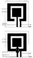
- the inner measuring electrode 1 shows a possible arrangement and configuration of the inner measuring electrode 1 and an outer measuring electrode 2 on a carrier 3.
- the inner measuring electrode 1 is applied to the carrier 3 in the form of a square area. However, any other shapes such as triangle, circle or irregular shapes are also possible for the inner measuring electrode 1.
- An opening in the outer measuring electrode 2 enables the inner measuring electrode 1 to be contacted with the aid of the Contact path 5.
- the outer measuring electrode 2 is contacted with the contact path 6.
- the carrier 3 can be a self-supporting solid electrolyte plate or else a pretreated, coated carrier substrate made of ceramic. Usual carrier substrates are made of aluminum oxide, for example. Materials which conduct oxygen ions, such as doped ZrO 2 , CeO 2 , HfO 2 or LaGaO 3 , are suitable as the solid electrolyte.
- Fig. 2 shows a further possible embodiment of the outer measuring electrode 2, in which the inner measuring electrode 1 is completely surrounded.
- insulating, gas-tight Layers required.
- the insulating, gas-tight layer 4 between the contact track 5 and the outer measuring electrode 2 arranged. It can also be the other way round to the display 2, first the contact track 5, then the insulating, gas-tight layer 4 and finally the outer measuring electrode 2 may be arranged.
- several external measuring electrodes is a wider and longer insulating, gas-tight layer or there are several insulating, gastight layers required.
- FIG. 3 shows, as an advantageous embodiment of the measuring electrodes, a circular inner measuring electrode 1 and a concentric outer measuring electrode 2.
- the located between the outer The circumference of the inner measuring electrode 1 and the inner circumference of the outer measuring electrode 2 forming diffusion gap has a constant width and enables one diffusing gas after reaching the inner measuring electrode 1 after the outer measuring electrode 2 was overcome.
- the outer dimensions of the carrier 3 adapted to the outer circumference of the outermost measuring electrode 2 are the diffusion path of a measuring gas to the outer periphery of the outermost Make the measuring electrode the same size on all sides. This possible configuration is not here shown.
- Fig. 5 shows an example of a plan view of the side of the measuring electrodes of a gas sensor according to the invention.
- the carrier 3a used here is the oxygen-ion-conductive solid electrolyte material ZrO 2 in the form of a self-supporting plate.
- the measuring electrodes 1; 2 are covered by the diffusion-limiting layer 7. It is necessary for the outer circumference of the outermost measuring electrode 2 to be covered and for all measuring electrodes to be covered by a closed layer of the diffusion-limiting layer 7. The position of the parts of the measuring electrodes lying under the diffusion-limiting layer 7 is indicated by dashed lines.
- the diffusion-limiting layer 7 is covered with a gas-tight layer 8.
- the arrangement of the measuring electrodes is chosen as in FIG. 3.
- the gas-tight layer 8 must also cover the edge of the diffusion-limiting layer 7 here.
- the measurement gas can hardly bypass the outermost measurement electrode 2 if the diffusion-limiting layer 7 extends outside the outermost measurement electrode 2 only to such an extent that the outermost circumference of the outermost measurement electrode 2 is covered.
- the gas-tight layer 8 must not cover the edges of the diffusion-limiting layer 7, so that the measuring gas can penetrate here and diffuse in the direction of the outermost measuring electrode 2.
- FIG. 6 shows a section A - A ′′ through the gas sensor from FIG. 5.
- the solid electrolyte plate is the carrier 3a arranged, the measuring electrodes 1; 2 and the counter electrodes 9; 10 carries.
- the counter electrodes 9; 10 are a vertical projection of the in this example Measuring electrodes 1; 2. But it is also possible that only a single counter electrode is used becomes.
- the measuring electrodes 1; 2 are covered by the diffusion-limiting layer 7. At Use of the laminate technique can be between the measuring electrodes 1; 2 a free space are formed, which has the height of the measuring electrodes.
- the diffusion-limiting Layer 7 is bounded by the gas-tight layer 8.
- the counter electrodes 9; 10 in addition to being able to apply a heating element 11, the counter electrodes 9; 10th covered by the porous, electrically insulating layer 12 which carries the heating element 11.
- the heating element 11 can, as provided here, be configured in a meandering shape.
- a carrier 3b made of a ceramic substrate, for example made of Al 2 O 3 carries the layer structure.
- the carrier 3b is covered with the diffusion-limiting layer 7, on which the measuring electrodes 1; 2 are arranged. Since the arrangement of the measuring electrodes is chosen here as in FIG. 3, the side and the edge of the diffusion-limiting layer 7 on which the contact tracks 5; 6 are guided away, limited by a gas-tight, insulating layer 14. Appropriate dimensions of the layer 14 are supplemented with a dashed line.
- the electrical insulation of the contact tracks of the measuring electrodes from the contact tracks of the counter electrodes can also be carried out with the aid of this gas-tight, insulating layer 14.
- the measuring electrodes 1; 2 and parts of the diffusion-limiting layer 7 are covered by a layer 13 made of solid electrolyte material, for example ZrO 2 .
- the marginal areas of the diffusion-limiting layer 7 remain free on three sides in order to allow gas access.
- the layer 13 made of solid electrolyte material bears directly over the measuring electrodes 1; 2 the counter electrodes 9; 10 in hatched representation.
- FIG. 7 also shows the porous, insulating layer 12, which serves as a base for a heating element shown only in FIG. 8.
- Fig. 8 shows a section B - B '' of the gas sensor from Fig. 7 with an additional, meandering Heating element 11 on the porous, insulating layer 12.
Landscapes
- Chemical & Material Sciences (AREA)
- Life Sciences & Earth Sciences (AREA)
- Health & Medical Sciences (AREA)
- Physics & Mathematics (AREA)
- Chemical Kinetics & Catalysis (AREA)
- Electrochemistry (AREA)
- Molecular Biology (AREA)
- Analytical Chemistry (AREA)
- Biochemistry (AREA)
- General Health & Medical Sciences (AREA)
- General Physics & Mathematics (AREA)
- Immunology (AREA)
- Pathology (AREA)
- Measuring Oxygen Concentration In Cells (AREA)
Abstract
Description

Claims (14)
- Gassensor mit mindestens je zwei Meßelektroden auf einer Oberseite und mindestens einer den Meßelektroden zugeordneten Gegenelektrode auf einer Unterseite eines ionenleitenden Festelektrolyten, wobei die dem ionenleitenden Festelektrolyten abgewandte Seite der Meßelektroden mit einer diffusions-limitierenden Schicht bedeckt ist und die dem ionenleitenden Festelektrolyten abgewandte Seite der diffusions-limitierenden Schicht mit ein er geschlossenen, gasdichten Schicht abgedeckt ist, dadurch gekennzeichnet, daß eine innere Meßelektrode (1) von mindestens einer äußeren Meßelektrode (2) beabstandet umgeben ist, daß der äußere Umfang der äußersten Meßelektrode (2) mit der diffusions-limitierenden Schicht (7) abgedeckt ist und daß ein Gaszutritt zu den Meßelektroden (1; 2) zwischen dem ionenleitenden Festelektrolyten (3a; 13) und der geschlossenen, gasdichten Schicht (3b; 8) im Bereich eines äußeren Umfangs der äußersten Meßelektrode (2) über die diffusions-limitierende Schicht (7) erfolgt.
- Gassensor nach Anspruch 1, dadurch gekennzeichet, daß die Anzahl der Gegenelektroden (9; 10) gleich der Anzahl der Meßelektroden (1;2) ist.
- Gassensor nach Anspruch 2, dadurch gekennzeichet, daß die Gegenelektroden (9; 10) auf der Unterseite des ionenleitenden Festelektrolyten (3a; 13) als eine senkrechte Projektion der Meßelektroden (1; 2) ausgebildet sind.
- Gassensor nach einem der Ansprüche 1 bis 3, dadurch gekennzeichet, daß die geschlossene, gasdichte Schicht (3b; 8) durch ein Trägersubstrat (3b) und/oder einen gasdichten Film (8) gebildet ist.
- Gassensor nach einem der Ansprüche 1 bis 4, dadurch gekennzeichet, daß ein sich zwischen den Meßelektroden (1; 2) bildender Diffusionsspalt mit der diffusions-limitierenden Schicht (7) gefüllt ist.
- Gassensor nach einem der Ansprüche 1 bis 5, dadurch gekennzeichet, daß die äußerste Meßelektrode (2) und deren Gegenelektrode (10) ein amperometrisches Meßsignal liefern.
- Gassensor nach einem der Ansprüche 1 bis 6, dadurch gekennzeichet, daß die Meß- und Gegenelektroden (1; 9) innerhalb der äußersten Meßelektrode und deren Gegenelektrode (2; 10) ein potentiometrisches Meßsignal liefern.
- Gassensor nach einem der Ansprüche 1 bis 7, dadurch gekennzeichet, daß das Meßsignal an der äußersten Meßelektrode (2) und deren Gegenelektrode (10) durch elektrochemische Umsetzung und Herauspumpen von Sauerstoff aus einem Meßgas gebildet ist.
- Gassensor nach einem der Ansprüche 1 bis 8, dadurch gekennzeichet, daß an den Meß- und Gegenelektroden (1; 9)innerhalb der äußersten Meßelektrode und deren Gegenelektrode (2; 10) nacheinander weitere in dem Meßgas enthaltene Gaskomponenten bestimmt werden.
- Gassensor nach Anspruch 9, dadurch gekennzeichet, daß als Gaskomponenten Kohlenwasserstoffe (CHx) und/oder Stickoxide (NOx) bestimmt werden.
- Gassensor nach einem der Ansprüche 1 bis 10, dadurch gekennzeichnet, daß die innere Meßelektrode (1) als Kreisfläche ausgebildet ist und mindestens eine äußere Meßelektrode (2) zumindest teilweise konzentrisch die innere Meßelektrode (1) beabstandet umgibt.
- Gassensor nach einem der Ansprüche 1 bis 11, dadurch gekennzeichet, daß die äußeren Meßelektroden (2) die innere Meßelektrode (1) vollständig konzentrisch umgeben und zwischen einer Kontaktbahn (5) zur Kontaktierung einer Meßelektrode und weiteren, diese Kontaktbahn kreuzenden Meßelektroden (2) eine elektrisch isolierende, gasdichte Schicht (4) angeordnet ist.
- Gassensor nach einem der Ansprüche 10 bis 12, dadurch gekennzeichet, daß der sich zwischen den Meßelektroden (1; 2) bildende Diffusionsspalt über seine Länge eine konstante Breite aufweist.
- Gassensor nach einem der Ansprüche 1 bis 13, dadurch gekennzeichnet, daß die Gegenelektroden (9; 10) mit einer elektrisch isolierenden, porösen Schicht (12) bedeckt sind und auf dieser ein elektrisches Heizelement (11) angeordnet ist.
Applications Claiming Priority (2)
| Application Number | Priority Date | Filing Date | Title |
|---|---|---|---|
| DE19921532A DE19921532A1 (de) | 1999-05-11 | 1999-05-11 | Gassensor mit diffusions-limitierender Schicht |
| DE19921532 | 1999-05-11 |
Publications (3)
| Publication Number | Publication Date |
|---|---|
| EP1052503A2 true EP1052503A2 (de) | 2000-11-15 |
| EP1052503A3 EP1052503A3 (de) | 2004-12-01 |
| EP1052503B1 EP1052503B1 (de) | 2007-11-14 |
Family
ID=7907605
Family Applications (1)
| Application Number | Title | Priority Date | Filing Date |
|---|---|---|---|
| EP00109425A Expired - Lifetime EP1052503B1 (de) | 1999-05-11 | 2000-05-03 | Gassensor mit diffusions-limitierender Schicht |
Country Status (5)
| Country | Link |
|---|---|
| EP (1) | EP1052503B1 (de) |
| JP (1) | JP2000338079A (de) |
| KR (1) | KR20000077139A (de) |
| BR (1) | BR0002407A (de) |
| DE (2) | DE19921532A1 (de) |
Cited By (1)
| Publication number | Priority date | Publication date | Assignee | Title |
|---|---|---|---|---|
| WO2005090955A1 (de) * | 2004-03-19 | 2005-09-29 | Robert Bosch Gmbh | Sensorelement |
Families Citing this family (3)
| Publication number | Priority date | Publication date | Assignee | Title |
|---|---|---|---|---|
| JP2006133106A (ja) * | 2004-11-08 | 2006-05-25 | Matsushita Electric Ind Co Ltd | 酸素ポンプ素子とそれを用いた酸素供給装置 |
| DE102006012088B4 (de) * | 2006-03-14 | 2008-02-14 | Heraeus Sensor Technology Gmbh | Verwendung einer epitaktischen Widerstandsstruktur als stoffsensitiven Sensor, Verfahren zum Betreiben des stoffsensitiven Sensors sowie stoffsensitiver Sensor |
| DE102011089304A1 (de) * | 2011-12-20 | 2013-06-20 | Continental Automotive Gmbh | Sensor zur Erfassung eines Gasgehalts in einer Umgebung des Sensors |
Family Cites Families (4)
| Publication number | Priority date | Publication date | Assignee | Title |
|---|---|---|---|---|
| DE2913866C2 (de) * | 1979-04-06 | 1987-03-12 | Robert Bosch Gmbh, 7000 Stuttgart | Meßfühler für die Bestimmung von Bestandteilen in strömenden Gasen |
| US5409591A (en) * | 1993-09-24 | 1995-04-25 | Baker; Charles K. | Selective electrochemical detector for nitric oxide and method |
| DE4442272A1 (de) * | 1994-11-28 | 1996-05-30 | Roth Technik Gmbh | Vorrichtung und Verfahren zur Bestimmung von gasförmigen Bestandteilen in Gasgemischen |
| DE19652968C2 (de) * | 1996-09-02 | 2003-11-13 | Bosch Gmbh Robert | Meßanordnung zur Bestimmung von Gasbestandteilen in Gasgemischen |
-
1999
- 1999-05-11 DE DE19921532A patent/DE19921532A1/de not_active Withdrawn
-
2000
- 2000-05-03 DE DE50014776T patent/DE50014776D1/de not_active Expired - Lifetime
- 2000-05-03 KR KR1020000023664A patent/KR20000077139A/ko not_active Withdrawn
- 2000-05-03 EP EP00109425A patent/EP1052503B1/de not_active Expired - Lifetime
- 2000-05-10 JP JP2000137080A patent/JP2000338079A/ja not_active Withdrawn
- 2000-05-10 BR BR0002407-4A patent/BR0002407A/pt not_active Application Discontinuation
Cited By (1)
| Publication number | Priority date | Publication date | Assignee | Title |
|---|---|---|---|---|
| WO2005090955A1 (de) * | 2004-03-19 | 2005-09-29 | Robert Bosch Gmbh | Sensorelement |
Also Published As
| Publication number | Publication date |
|---|---|
| DE50014776D1 (de) | 2007-12-27 |
| KR20000077139A (ko) | 2000-12-26 |
| JP2000338079A (ja) | 2000-12-08 |
| EP1052503B1 (de) | 2007-11-14 |
| EP1052503A3 (de) | 2004-12-01 |
| BR0002407A (pt) | 2001-01-02 |
| DE19921532A1 (de) | 2000-11-30 |
Similar Documents
| Publication | Publication Date | Title |
|---|---|---|
| EP0750744B1 (de) | Miniaturisierte durchflussmesskammer mit integrierten chemo- und/oder biosensorelementen | |
| DE2928496C2 (de) | ||
| EP0810431B1 (de) | Elektrochemischer Sensor | |
| DE10359173B4 (de) | Messvorrichtung mit mehreren auf einem Substrat angeordneten potentiometrischen Elektrodenpaaren | |
| EP2766719B1 (de) | Sensor und verfahren zum herstellen eines sensors | |
| DE4445033A1 (de) | Verfahren zur Messung der Konzentration eines Gases in einem Gasgemisch sowie elektrochemischer Sensor zur Bestimmung der Gaskonzentration | |
| DE10120083A1 (de) | Meßelektrodenpaar, Biosensor mit einem solchen Meßelektrodenpaar und Verfahren zur Herstellung | |
| DE2933971C2 (de) | Gassensor hoher Empfindlichkeit und Stabilität zum Nachweis und zur Messung des Verunreinigungsgehaltes von Luft auf der Basis von Metalloxidhalbleitern | |
| DE102013109357A1 (de) | Ionensensitive Schichtstruktur für einen ionensensitiven Sensor und Verfahren zur Herstellung derselben | |
| DE19930636A1 (de) | Elektrochemischer Gassensor und Verfahren zur Bestimmung von Gaskomponenten | |
| DE4401749A1 (de) | Sauerstoffkonzentrationssensor | |
| EP1052503B1 (de) | Gassensor mit diffusions-limitierender Schicht | |
| DE3709516C2 (de) | Sauerstoffsensor | |
| EP0647319A1 (de) | Sensorelement zur bestimmung der gaskomponentenkonzentration | |
| EP0408039A2 (de) | Grenzstromsensor zum Messen des Partialdrucks eines Gases | |
| DE2460113A1 (de) | Messzelle zur bestimmung von sauerstoffkonzentrationen in einem gasgemisch | |
| DE19631530C2 (de) | Ionenselektiver Sensor | |
| DE102008043932A1 (de) | Sensorelement mit Trägerelement | |
| EP1728071A1 (de) | Sensorelement | |
| DE3151891A1 (de) | Halbleiter-sensor fuer die messung der konzentration von teilchen in fluiden | |
| DE4025785A1 (de) | Messeinrichtung fuer ph-werte | |
| EP2294390A1 (de) | Sgfet-gassensor | |
| EP1506391B1 (de) | Sensor für einen elektrochemischen messfühler | |
| DE3529950C2 (de) | ||
| DE19701798C2 (de) | Elektrochemische Durchflußzelle |
Legal Events
| Date | Code | Title | Description |
|---|---|---|---|
| PUAI | Public reference made under article 153(3) epc to a published international application that has entered the european phase |
Free format text: ORIGINAL CODE: 0009012 |
|
| 17P | Request for examination filed |
Effective date: 20000510 |
|
| AK | Designated contracting states |
Kind code of ref document: A2 Designated state(s): AT BE CH CY DE DK ES FI FR GB GR IE IT LI LU MC NL PT SE |
|
| AX | Request for extension of the european patent |
Free format text: AL;LT;LV;MK;RO;SI |
|
| RAP1 | Party data changed (applicant data changed or rights of an application transferred) |
Owner name: J. DITTRICH ELEKTRONIC GMBH & CO.KG, |
|
| PUAL | Search report despatched |
Free format text: ORIGINAL CODE: 0009013 |
|
| AK | Designated contracting states |
Kind code of ref document: A3 Designated state(s): AT BE CH CY DE DK ES FI FR GB GR IE IT LI LU MC NL PT SE |
|
| AX | Request for extension of the european patent |
Extension state: AL LT LV MK RO SI |
|
| AKX | Designation fees paid |
Designated state(s): DE FR IT |
|
| GRAP | Despatch of communication of intention to grant a patent |
Free format text: ORIGINAL CODE: EPIDOSNIGR1 |
|
| RBV | Designated contracting states (corrected) |
Designated state(s): DE FR GB IT |
|
| GRAS | Grant fee paid |
Free format text: ORIGINAL CODE: EPIDOSNIGR3 |
|
| GRAA | (expected) grant |
Free format text: ORIGINAL CODE: 0009210 |
|
| AK | Designated contracting states |
Kind code of ref document: B1 Designated state(s): DE FR GB IT |
|
| REG | Reference to a national code |
Ref country code: GB Ref legal event code: FG4D Free format text: NOT ENGLISH |
|
| REF | Corresponds to: |
Ref document number: 50014776 Country of ref document: DE Date of ref document: 20071227 Kind code of ref document: P |
|
| GBV | Gb: ep patent (uk) treated as always having been void in accordance with gb section 77(7)/1977 [no translation filed] | ||
| EN | Fr: translation not filed | ||
| PLBE | No opposition filed within time limit |
Free format text: ORIGINAL CODE: 0009261 |
|
| STAA | Information on the status of an ep patent application or granted ep patent |
Free format text: STATUS: NO OPPOSITION FILED WITHIN TIME LIMIT |
|
| 26N | No opposition filed |
Effective date: 20080815 |
|
| PG25 | Lapsed in a contracting state [announced via postgrant information from national office to epo] |
Ref country code: FR Free format text: LAPSE BECAUSE OF FAILURE TO SUBMIT A TRANSLATION OF THE DESCRIPTION OR TO PAY THE FEE WITHIN THE PRESCRIBED TIME-LIMIT Effective date: 20080829 |
|
| PG25 | Lapsed in a contracting state [announced via postgrant information from national office to epo] |
Ref country code: GB Free format text: LAPSE BECAUSE OF FAILURE TO SUBMIT A TRANSLATION OF THE DESCRIPTION OR TO PAY THE FEE WITHIN THE PRESCRIBED TIME-LIMIT Effective date: 20071114 |
|
| PG25 | Lapsed in a contracting state [announced via postgrant information from national office to epo] |
Ref country code: DE Free format text: LAPSE BECAUSE OF NON-PAYMENT OF DUE FEES Effective date: 20081202 |
|
| PGRI | Patent reinstated in contracting state [announced from national office to epo] |
Ref country code: DE Effective date: 20090512 |
|
| PG25 | Lapsed in a contracting state [announced via postgrant information from national office to epo] |
Ref country code: IT Free format text: LAPSE BECAUSE OF NON-PAYMENT OF DUE FEES Effective date: 20080531 |
|
| PGFP | Annual fee paid to national office [announced via postgrant information from national office to epo] |
Ref country code: DE Payment date: 20110524 Year of fee payment: 12 |
|
| REG | Reference to a national code |
Ref country code: DE Ref legal event code: R119 Ref document number: 50014776 Country of ref document: DE Effective date: 20121201 |
|
| PG25 | Lapsed in a contracting state [announced via postgrant information from national office to epo] |
Ref country code: DE Free format text: LAPSE BECAUSE OF NON-PAYMENT OF DUE FEES Effective date: 20121201 |