EP1052182B1 - Kunststoffbehälter und Verfahren zu seiner Herstellung - Google Patents
Kunststoffbehälter und Verfahren zu seiner Herstellung Download PDFInfo
- Publication number
- EP1052182B1 EP1052182B1 EP00302060A EP00302060A EP1052182B1 EP 1052182 B1 EP1052182 B1 EP 1052182B1 EP 00302060 A EP00302060 A EP 00302060A EP 00302060 A EP00302060 A EP 00302060A EP 1052182 B1 EP1052182 B1 EP 1052182B1
- Authority
- EP
- European Patent Office
- Prior art keywords
- formed member
- main body
- container
- film
- laminate
- Prior art date
- Legal status (The legal status is an assumption and is not a legal conclusion. Google has not performed a legal analysis and makes no representation as to the accuracy of the status listed.)
- Expired - Lifetime
Links
Images


Classifications
-
- B—PERFORMING OPERATIONS; TRANSPORTING
- B05—SPRAYING OR ATOMISING IN GENERAL; APPLYING FLUENT MATERIALS TO SURFACES, IN GENERAL
- B05C—APPARATUS FOR APPLYING FLUENT MATERIALS TO SURFACES, IN GENERAL
- B05C17/00—Hand tools or apparatus using hand held tools, for applying liquids or other fluent materials to, for spreading applied liquids or other fluent materials on, or for partially removing applied liquids or other fluent materials from, surfaces
- B05C17/005—Hand tools or apparatus using hand held tools, for applying liquids or other fluent materials to, for spreading applied liquids or other fluent materials on, or for partially removing applied liquids or other fluent materials from, surfaces for discharging material from a reservoir or container located in or on the hand tool through an outlet orifice by pressure without using surface contacting members like pads or brushes
- B05C17/00583—Hand tools or apparatus using hand held tools, for applying liquids or other fluent materials to, for spreading applied liquids or other fluent materials on, or for partially removing applied liquids or other fluent materials from, surfaces for discharging material from a reservoir or container located in or on the hand tool through an outlet orifice by pressure without using surface contacting members like pads or brushes the container for the material to be dispensed being deformable
-
- B—PERFORMING OPERATIONS; TRANSPORTING
- B05—SPRAYING OR ATOMISING IN GENERAL; APPLYING FLUENT MATERIALS TO SURFACES, IN GENERAL
- B05C—APPARATUS FOR APPLYING FLUENT MATERIALS TO SURFACES, IN GENERAL
- B05C17/00—Hand tools or apparatus using hand held tools, for applying liquids or other fluent materials to, for spreading applied liquids or other fluent materials on, or for partially removing applied liquids or other fluent materials from, surfaces
- B05C17/005—Hand tools or apparatus using hand held tools, for applying liquids or other fluent materials to, for spreading applied liquids or other fluent materials on, or for partially removing applied liquids or other fluent materials from, surfaces for discharging material from a reservoir or container located in or on the hand tool through an outlet orifice by pressure without using surface contacting members like pads or brushes
- B05C17/00576—Hand tools or apparatus using hand held tools, for applying liquids or other fluent materials to, for spreading applied liquids or other fluent materials on, or for partially removing applied liquids or other fluent materials from, surfaces for discharging material from a reservoir or container located in or on the hand tool through an outlet orifice by pressure without using surface contacting members like pads or brushes characterised by the construction of a piston as pressure exerting means, or of the co-operating container
-
- B—PERFORMING OPERATIONS; TRANSPORTING
- B05—SPRAYING OR ATOMISING IN GENERAL; APPLYING FLUENT MATERIALS TO SURFACES, IN GENERAL
- B05C—APPARATUS FOR APPLYING FLUENT MATERIALS TO SURFACES, IN GENERAL
- B05C17/00—Hand tools or apparatus using hand held tools, for applying liquids or other fluent materials to, for spreading applied liquids or other fluent materials on, or for partially removing applied liquids or other fluent materials from, surfaces
- B05C17/005—Hand tools or apparatus using hand held tools, for applying liquids or other fluent materials to, for spreading applied liquids or other fluent materials on, or for partially removing applied liquids or other fluent materials from, surfaces for discharging material from a reservoir or container located in or on the hand tool through an outlet orifice by pressure without using surface contacting members like pads or brushes
- B05C17/00586—Means, generally located near the nozzle, for piercing or perforating the front part of a cartridge
-
- B—PERFORMING OPERATIONS; TRANSPORTING
- B05—SPRAYING OR ATOMISING IN GENERAL; APPLYING FLUENT MATERIALS TO SURFACES, IN GENERAL
- B05C—APPARATUS FOR APPLYING FLUENT MATERIALS TO SURFACES, IN GENERAL
- B05C17/00—Hand tools or apparatus using hand held tools, for applying liquids or other fluent materials to, for spreading applied liquids or other fluent materials on, or for partially removing applied liquids or other fluent materials from, surfaces
- B05C17/005—Hand tools or apparatus using hand held tools, for applying liquids or other fluent materials to, for spreading applied liquids or other fluent materials on, or for partially removing applied liquids or other fluent materials from, surfaces for discharging material from a reservoir or container located in or on the hand tool through an outlet orifice by pressure without using surface contacting members like pads or brushes
- B05C17/01—Hand tools or apparatus using hand held tools, for applying liquids or other fluent materials to, for spreading applied liquids or other fluent materials on, or for partially removing applied liquids or other fluent materials from, surfaces for discharging material from a reservoir or container located in or on the hand tool through an outlet orifice by pressure without using surface contacting members like pads or brushes with manually mechanically or electrically actuated piston or the like
-
- B—PERFORMING OPERATIONS; TRANSPORTING
- B29—WORKING OF PLASTICS; WORKING OF SUBSTANCES IN A PLASTIC STATE IN GENERAL
- B29C—SHAPING OR JOINING OF PLASTICS; SHAPING OF MATERIAL IN A PLASTIC STATE, NOT OTHERWISE PROVIDED FOR; AFTER-TREATMENT OF THE SHAPED PRODUCTS, e.g. REPAIRING
- B29C45/00—Injection moulding, i.e. forcing the required volume of moulding material through a nozzle into a closed mould; Apparatus therefor
- B29C45/14—Injection moulding, i.e. forcing the required volume of moulding material through a nozzle into a closed mould; Apparatus therefor incorporating preformed parts or layers, e.g. injection moulding around inserts or for coating articles
- B29C45/1418—Injection moulding, i.e. forcing the required volume of moulding material through a nozzle into a closed mould; Apparatus therefor incorporating preformed parts or layers, e.g. injection moulding around inserts or for coating articles the inserts being deformed or preformed, e.g. by the injection pressure
-
- B—PERFORMING OPERATIONS; TRANSPORTING
- B29—WORKING OF PLASTICS; WORKING OF SUBSTANCES IN A PLASTIC STATE IN GENERAL
- B29C—SHAPING OR JOINING OF PLASTICS; SHAPING OF MATERIAL IN A PLASTIC STATE, NOT OTHERWISE PROVIDED FOR; AFTER-TREATMENT OF THE SHAPED PRODUCTS, e.g. REPAIRING
- B29C45/00—Injection moulding, i.e. forcing the required volume of moulding material through a nozzle into a closed mould; Apparatus therefor
- B29C45/14—Injection moulding, i.e. forcing the required volume of moulding material through a nozzle into a closed mould; Apparatus therefor incorporating preformed parts or layers, e.g. injection moulding around inserts or for coating articles
- B29C45/14336—Coating a portion of the article, e.g. the edge of the article
-
- B—PERFORMING OPERATIONS; TRANSPORTING
- B29—WORKING OF PLASTICS; WORKING OF SUBSTANCES IN A PLASTIC STATE IN GENERAL
- B29C—SHAPING OR JOINING OF PLASTICS; SHAPING OF MATERIAL IN A PLASTIC STATE, NOT OTHERWISE PROVIDED FOR; AFTER-TREATMENT OF THE SHAPED PRODUCTS, e.g. REPAIRING
- B29C45/00—Injection moulding, i.e. forcing the required volume of moulding material through a nozzle into a closed mould; Apparatus therefor
- B29C45/14—Injection moulding, i.e. forcing the required volume of moulding material through a nozzle into a closed mould; Apparatus therefor incorporating preformed parts or layers, e.g. injection moulding around inserts or for coating articles
- B29C45/14688—Coating articles provided with a decoration
-
- B—PERFORMING OPERATIONS; TRANSPORTING
- B29—WORKING OF PLASTICS; WORKING OF SUBSTANCES IN A PLASTIC STATE IN GENERAL
- B29C—SHAPING OR JOINING OF PLASTICS; SHAPING OF MATERIAL IN A PLASTIC STATE, NOT OTHERWISE PROVIDED FOR; AFTER-TREATMENT OF THE SHAPED PRODUCTS, e.g. REPAIRING
- B29C45/00—Injection moulding, i.e. forcing the required volume of moulding material through a nozzle into a closed mould; Apparatus therefor
- B29C45/16—Making multilayered or multicoloured articles
- B29C45/1671—Making multilayered or multicoloured articles with an insert
-
- B—PERFORMING OPERATIONS; TRANSPORTING
- B65—CONVEYING; PACKING; STORING; HANDLING THIN OR FILAMENTARY MATERIAL
- B65D—CONTAINERS FOR STORAGE OR TRANSPORT OF ARTICLES OR MATERIALS, e.g. BAGS, BARRELS, BOTTLES, BOXES, CANS, CARTONS, CRATES, DRUMS, JARS, TANKS, HOPPERS, FORWARDING CONTAINERS; ACCESSORIES, CLOSURES, OR FITTINGS THEREFOR; PACKAGING ELEMENTS; PACKAGES
- B65D15/00—Containers having bodies formed by interconnecting or uniting two or more rigid, or substantially rigid, sections made of different materials
- B65D15/02—Containers having bodies formed by interconnecting or uniting two or more rigid, or substantially rigid, sections made of different materials of curved, or partially curved, cross-section, e.g. cans, drums
- B65D15/16—Containers having bodies formed by interconnecting or uniting two or more rigid, or substantially rigid, sections made of different materials of curved, or partially curved, cross-section, e.g. cans, drums with curved, or partially curved, walls made of plastics material
-
- B—PERFORMING OPERATIONS; TRANSPORTING
- B65—CONVEYING; PACKING; STORING; HANDLING THIN OR FILAMENTARY MATERIAL
- B65D—CONTAINERS FOR STORAGE OR TRANSPORT OF ARTICLES OR MATERIALS, e.g. BAGS, BARRELS, BOTTLES, BOXES, CANS, CARTONS, CRATES, DRUMS, JARS, TANKS, HOPPERS, FORWARDING CONTAINERS; ACCESSORIES, CLOSURES, OR FITTINGS THEREFOR; PACKAGING ELEMENTS; PACKAGES
- B65D33/00—Details of, or accessories for, sacks or bags
- B65D33/02—Local reinforcements or stiffening inserts, e.g. wires, strings, strips or frames
-
- B—PERFORMING OPERATIONS; TRANSPORTING
- B65—CONVEYING; PACKING; STORING; HANDLING THIN OR FILAMENTARY MATERIAL
- B65D—CONTAINERS FOR STORAGE OR TRANSPORT OF ARTICLES OR MATERIALS, e.g. BAGS, BARRELS, BOTTLES, BOXES, CANS, CARTONS, CRATES, DRUMS, JARS, TANKS, HOPPERS, FORWARDING CONTAINERS; ACCESSORIES, CLOSURES, OR FITTINGS THEREFOR; PACKAGING ELEMENTS; PACKAGES
- B65D83/00—Containers or packages with special means for dispensing contents
- B65D83/771—Containers or packages with special means for dispensing contents for dispensing fluent contents by means of a flexible bag or a deformable membrane or diaphragm
- B65D83/7713—Containers or packages with special means for dispensing contents for dispensing fluent contents by means of a flexible bag or a deformable membrane or diaphragm the contents of a flexible bag being expelled by a piston, or a movable bottom or partition provided in the container or the package
-
- B—PERFORMING OPERATIONS; TRANSPORTING
- B29—WORKING OF PLASTICS; WORKING OF SUBSTANCES IN A PLASTIC STATE IN GENERAL
- B29L—INDEXING SCHEME ASSOCIATED WITH SUBCLASS B29C, RELATING TO PARTICULAR ARTICLES
- B29L2023/00—Tubular articles
- B29L2023/20—Flexible squeeze tubes, e.g. for cosmetics
-
- B—PERFORMING OPERATIONS; TRANSPORTING
- B29—WORKING OF PLASTICS; WORKING OF SUBSTANCES IN A PLASTIC STATE IN GENERAL
- B29L—INDEXING SCHEME ASSOCIATED WITH SUBCLASS B29C, RELATING TO PARTICULAR ARTICLES
- B29L2031/00—Other particular articles
- B29L2031/712—Containers; Packaging elements or accessories, Packages
- B29L2031/715—Caulking cartridges
-
- Y—GENERAL TAGGING OF NEW TECHNOLOGICAL DEVELOPMENTS; GENERAL TAGGING OF CROSS-SECTIONAL TECHNOLOGIES SPANNING OVER SEVERAL SECTIONS OF THE IPC; TECHNICAL SUBJECTS COVERED BY FORMER USPC CROSS-REFERENCE ART COLLECTIONS [XRACs] AND DIGESTS
- Y10—TECHNICAL SUBJECTS COVERED BY FORMER USPC
- Y10T—TECHNICAL SUBJECTS COVERED BY FORMER US CLASSIFICATION
- Y10T428/00—Stock material or miscellaneous articles
- Y10T428/13—Hollow or container type article [e.g., tube, vase, etc.]
- Y10T428/1352—Polymer or resin containing [i.e., natural or synthetic]
- Y10T428/139—Open-ended, self-supporting conduit, cylinder, or tube-type article
Definitions
- the present invention relates to a method of manufacturing a plastic container, and to a plastic container which is suitable for receiving contents in the form of powder, particle or liquid.
- Containers for receiving solids such as ground coffee beans, the moisture of which should be decreased, are required to be formed of material through which moisture cannot pass.
- glass containers, metallic cans or plastic containers obtained by a blow molding method are generally used.
- Glass containers and metallic cans have excellent moisture-proof, gas isolating, and good storage properties. They do however have problems relating to the weight and volume of the container itself, which may hinder disposal of the used container.
- Plastic containers obtained by a blow molding method can solve the problems of weight and volume of a glass container or a metallic can. It is, however, impossible to decrease the thickness of a plastic container under 0.7 mm by conventional blow molding methods. Accordingly, for plastic containers obtained by a blow molding method, only a co-extruded article of a barrier base material such as ethylene vinyl alcohol (EVOH) copolymer resins (i.e., "EVAL® ”) and a synthetic resin material such as polyethylene, polypropylene or the like can provide appropriate moisture-proof and gas isolating properties.
- EVOH ethylene vinyl alcohol copolymer resins
- EVAL® synthetic resin material
- Containers may otherwise be manufactured by putting an intermediate tubular body formed of a plastic laminate film on a mandrel serving as a core for a mold; putting upper and lower local molds on the mandrel in which the intermediate tubular body has already been put; and injecting synthetic resin material in a molten state into the upper and lower local molds by an insert-injection process so as to form upper and lower formed members integrally with the outer surface of the intermediate tubular body.
- Plastic containers 1 obtained by the above-described method, may comprise an intermediate tubular body 2, an upper formed member 3 integrally connected to the outer surface of the upper end portion of the intermediate tubular body 2, a lower formed member 4 integrally connected to an outer surface of the lower end portion of the intermediate tubular body 2 and a cover member 5 for closing the opening end of the upper formed member 3, as shown in FIG. 6.
- the intermediate tubular body of the plastic container is formed of plastic laminate film to enable multicolor printing on the outer surface of the intermediate tubular body.
- a disadvantage of this style of container, is that the upper and lower formed members formed on the outer surface of the intermediate tubular body decrease the effective area on which the printing may be applied.
- US patent No. 5, 873,970 discloses a method of manufacturing a plastic container, comprising the steps of:
- the present invention seeks to reduce some of the disadvantages outlined above.
- a method of manufacturing a plastic container as defined above is characterised in that:
- a method of the present invention further comprises the step of:
- a method of manufacturing as disclosed in the present invention has the advantage that a mandrel can smoothly be inserted into a mold, the mold having a first cavity formed with a larger inner diameter than an outer diameter of a second cavity formed in the mold.
- this method also enables the mandrel to be pulled out easily without hindering the first formed member.
- a further advantage of the present invention is that it is possible to prevent wrinkles from occurring at the end of the tubular body and to prevent the end thereof from being turned up during the insert-injection process.
- a plastic container comprises:
- Embodiments of this invention provide a plastic container with a larger effective area on which printing is enabled, in comparison with conventional plastic containers. This printing area is provided on the tubular body. Locating the second formed member inside the main body provides a larger effective area of the main body, on which to print.
- the first formed member and the second formed member are arranged so that a mandrel used in the insert-injection process may be pulled out of the main body without being hindered.
- a container of the present invention has a grip portion formed on an outer surface at a lower end of the first formed member.
- FIG. 1 illustrates an embodiment of the present invention, in which a plastic container is used as a container for ground coffee beans or powdery coffee (hereinafter referred to as the "coffee-container").
- the coffee-container 10 is composed of a main body 11 that is formed of a plastic laminate film in a tubular shape, an upper-formed member 12 that is integrally formed with the outer surface of one end of the main body 11 and a lower-formed member 13 that is integrally formed with the inner surface of the other end of the main body 11.
- the upper formed member 12 is formed into a tubular shape, and is provided with an upper opening end having an inside diameter R1.
- the upper-formed member 12 is provided on the outer surface of its upper portion with a threaded portion 14 and on the outer surface of its lower portion with a grip portion 15.
- the upper opening end of the upper-formed member 12 is sealed with a cover member.
- a cap (not shown) is screwed on the thread portion 14 of the upper-formed member 12.
- the lower-formed member 13 is formed into a tubular shape with a bottom having an outside diameter R2.
- the outside diameter R2 of the lower-formed member 13 is designed to be smaller than the inside diameter R1 of the upper-formed member 12. More specifically, the upper-formed member 12 serves as the large-diameter-formed member and the lower-formed member 13 serves as the small-diameter-formed member.
- the main body 11 is of tubular shape with opposite opening ends. As illustrated in FIGS. 8 to 11, it can be obtained by cutting a plastic laminate film into a rectangular shape to form a sheet material and then joining the outer surface of one side edge of the thus formed sheet material with the inner surface of the other side edge thereof.
- a different process may be adopted involving joining the inner surface of the one side edge of the sheet material with the inner surface of the other side edge thereof (hereinafter referred to as the "first optional joining process").
- a different process that may be adopted involves placing the outer surface of the one side edge of the sheet material with the inner surface of the other side edge thereof and joining them with the use of an adhesive tape applied from the inside of the main body (hereinafter referred to as the "second optional joining process").
- plastic laminate film (i) a laminate of polyethylene film having a thickness of 70 ⁇ m, a polyester film having a thickness of 12 ⁇ m, an aluminium foil having a thickness of 12 ⁇ m and a polyethylene film having a thickness of 70 ⁇ m, (ii) a laminate of a cast polypropylene having a thickness of 70 ⁇ m, a polyester film having a thickness of 12 ⁇ m, an aluminium foil having a thickness of 12 ⁇ m and a cast polypropylene having a thickness of 70 ⁇ m or (iii) a laminate of a cast polypropylene having a thickness of 70 ⁇ m, a polyester film having a thickness of 12 ⁇ m and a cast polypropylene having a thickness of 70 ⁇ m.
- the aluminum film is substituted by a film of ethylene-vinylalcohol copolymer or a silica-deposited film, it is possible to make the main body transparent, while maintaining the excellent moisture-proof property and gas isolating property.
- the contents received in the container can visually be observed from the outside thereof.
- the main body 11 for the coffee-container 10 is formed of the plastic laminate film including the aluminum foil, it is preferable to adopt the first or second optional joining process described above.
- the contents to be received in the container is liquid such as fruit juice drink, which has a pH value of up to 4, it is preferable to adopt the second optional joining process for the formation of the main body 11 in order to prevent the aluminum foil from being oxidized to cause elution of aluminum in the liquid.
- the main body 11 for the coffee-container 10 is formed of the plastic laminate film including no aluminum foil, it is preferable to adopt the first or second optional joining process for the formation of the main body 11 in order to prevent the adhesive used in the lamination process from being eluted into the contents received in the container.
- the moisture of ground coffee beans or powdery coffee should be decreased as small as possible and the good aroma thereof should be maintained. Accordingly, the coffee-container 10 is required to have the excellent moisture-proof property and the excellent gas isolating property. For these reasons, the plastic laminate film having these excellent properties is selected to be used for the formation of the main body 11 for the coffee-container 10.
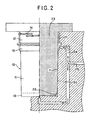
- a mold 20 for the formation of the coffee-container 10 has the first cavity 21 for forming the large-diameter-formed member and the second cavity 22 for forming the small-diameter-formed member as shown in FIG. 2.
- the first cavity 21 and the second cavity 22 are spaced from each other at a distance corresponding to the dimensions of the main body 11.
- the first cavity 21 has an inside diameter, which is larger than the outside diameter of the second cavity 22.
- the first cavity 21 of the mold has a shape corresponding to the upper-formed member 12 of the above-described coffee-container 10.
- the second cavity 22 of the mold has a shape corresponding to the lower-formed member 13 thereof.
- the lower-formed member 13, which is formed by the second cavity 22, has a bottom that provides the excellent moisture-proof property and the excellent gas isolating property.
- the main body 11 is formed into a tubular shape of the plastic laminate film having the excellent moisture-proof property and the excellent gas isolating property.
- the thus formed main tubular body 11 is put on the outer surface of a mandrel 23, which serves as a core for the mold.
- the mandrel 23 also has the corresponding circular cross section.
- the mandrel 23 also has, on the other hand, the corresponding rectangular cross section.
- the mandrel 23 on which the main tubular body 11 has been put is placed in the mold 20 so that the end of the main tubular body 11 locates inside the first cavity 21 and the other end thereof locates outside the second cavity 22.
- the mandrel 23, on which the main tubular body 11 has been put can smoothly be inserted into the mold 20 due to the fact that the inside diameter of the first cavity 21 of the mold 20 is larger than the outside diameter of the second cavity 22 thereof.
- the formation of the coffee-container 10 in which the upper-formed member 12 is integrally formed with the outer surface of the end of the main tubular body 11 and the lower-formed member 13 is integrally formed with the inner surface of the other end of the main tubular body 11.
- the mandrel 23 placed in the mold 20 is pulled out after the formation of the coffee-container 10. It is possible to pull out easily the mandrel 23 from the mold without being hindered by the upper-formed member 13 due to the fact that the inside diameter of the first cavity 21 of the mold 20 is larger than the outside diameter of the second cavity 22 thereof.
- the lower-formed member i.e., the smaller-diameter-formed member 13 which is joined to the lower end of the main tubular body 11, locates on the inner surface of the main tubular body 11. As a result, it is possible to increase the effective area, on which the printing is to be applied, by an area occupied by the smaller-diameter-formed member 13.
- the upper-formed member 12 is integrally formed with the outer surface of the end of the main body 11, which is formed into the tubular shape of the plastic laminate film, and the lower-formed member 13 is integrally formed with the inner surface of the other end of the main body 11. It is possible to form the coffee-container 10 in which the upper-formed member 12 is integrally formed with the inner surface of the end of the main body 11, by changing the positional relationship between the mold 20 and the mandrel 23 on the outer surface of which the main body 11 is put. According to such a coffee-container 10, it is possible to increase the effective area, on which the printing is to be applied, by the total area occupied by the small-diameter-formed member 13 and the large-diameter-formed member 12.
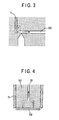
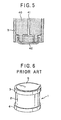
- FIGS. 4 and 5 show another embodiment of the present invention.
- a suction line 31 is formed in the mandrel 30 on the outer surface of which the main tubular body 11 is put.
- a laminate film 32 can be placed on the lower surface of the mandrel 30 by a suction effect. It is therefore possible to join the laminate film 32 integrally with the smaller-diameter-formed member 13 by injecting the synthetic resin material such as polyethylene resin in a molten state into the smalter-diameter-formed member 13 by means of the insert-injection process.
- plastic laminate film 32 (i) a laminate of a polyethylene film having a thickness of 70 ⁇ m, a polyester film having a thickness of 12 ⁇ m, an aluminum foil having a thickness of 12 ⁇ m and a polyethylene film having a thickness of 70 ⁇ m, (ii) a laminate of a polyethylene film having a thickness of 70 ⁇ m, a polyester film having a thickness of 12 ⁇ m, a film of ethylene vinyl alcohol (EVOH) copolymer resins (i.e., "EVAL" (trademark)) having a thickness of 15 ⁇ m and a polyethylene film having a thickness of 70 ⁇ m or (iii) a laminate of a polyethylene film having a thickness of 70 ⁇ m, a polyester film having a thickness of 12 ⁇ m, an aluminum foil having a thickness of 40 ⁇ m and a polyethylene film having a thickness of 70 ⁇ m.
- EVOH ethylene vinyl alcohol
- a suction line 41 is formed in the mandrel 40 on the outer surface of which the main tubular body 11 is put.
- a synthetic resin-formed body 42 which has previously been formed, can be placed on the lower surface of the mandrel 40 by a suction effect. It is therefore possible to join the synthetic resin-formed body 42 integrally with the smaller-diameter-formed member 13 by injecting the synthetic resin material such as polyethylene resin in a molten state into the smaller-diameter-formed member 13 by means of the insert-injection process.
- the synthetic resin-formed body 42 can be obtained by subjecting a polyethylene film having a thickness of 70 ⁇ m, a polyester film having a thickness of 12 ⁇ m, an aluminium foil having a thickness of 40 ⁇ m and a polyethylene film having a thickness of 7 ⁇ m to a press-forming process.
- a polyethylene film having a thickness of 70 ⁇ m a polyethylene film having a thickness of 70 ⁇ m
- a polyester film having a thickness of 12 ⁇ m an aluminium foil having a thickness of 40 ⁇ m
- a polyethylene film having a thickness of 7 ⁇ m to a press-forming process.
- FIG. 8 shows a container for fluid that is not an embodiment of the present invention. However, FIG. 8 illustrates various aspects of the present invention, in particular how the container of the present invention is formed from the laminate.
- the container 51 for fluid is composed of a main body 60 having opposite opening ends, i.e., front and rear opening ends, and of a pair of closing devices, i.e., a front-bottom member 70 for closing the front opening end of the main body 60 and a rear bottom member 80 for closing the rear opening end of the main body 60.
- the main body 60 is formed of a laminate 61 in a tubular shape.
- the laminate 61 comprises a plurality of flexible films (in general, at least three flexible films).
- the main body 60 tapers off from one end (i.e., the left-hand end in FIG. 8, hereinafter referred to as the "front end") to the other end (i.e., the right-hand end in FIG. 8, hereinafter referred to as the "rear end").
- the main body 60 can receive in its inside various fluid such as adhesive, sealant, jam or the like.
- the width of the laminate 61 becomes gradually smaller from the front end to the rear end as shown in FIG. 11 in correspondence to the tapered main body 11.
- the main body 11 can be formed by joining one longitudinal edge of the laminate 61 with the other longitudinal edge thereof as described later.
- the laminate 61 is composed of four films, i.e., the first to fourth films 62 to 65 as shown in FIG. 7, which locate from the outer peripheral side of the main body 11 toward the inner peripheral side thereof in this order.
- first film 62 It is preferable to use a film having excellent scratch resistance and a small coefficient of friction, as the first film 62.
- Resin film is generally used as the first film 62.
- a transparent polyethylene film having a thickness of from 30 ⁇ m to 60 ⁇ m.
- a cast polypropylene (CPP) film may be used.
- the second film 63 is also a resin film. Characters, devices, symbols and the like can easily be printed on the surface (appearing on the outer peripheral side of the main body 11) of the above-mentioned resin film.
- a polyester film having a thickness of from 12 ⁇ m to 16 ⁇ m is used.
- a film of nylon or oriented polypropylene (OPP) may be used alternatively.
- the transparent first film 62 permits the characters or the like printed on the surface of the second film 63 to be observed visually from the outside of the main body 11.
- the third film 64 has a function of imparting non-permeability to the laminate 61.
- a metallic foil is usually used as the third film 64. With respect to the metallic film, it is preferable to use an aluminium foil having a light weight.
- the aluminium foil preferably has a thickness of from 9 ⁇ m to 12 ⁇ m.
- the fourth film 65 has a function of protecting the third film 64, which is formed of the aluminium foil to prevent it from breaking during the manufacturing process of the container 51.
- a resin film is usually used as the fourth film 65.
- material for forming the fourth film 65 There is no specific limitation of material for forming the fourth film 65.
- the same polyethylene film as the first film 62 is used in this embodiment in view of the fact that the main body 11 is formed of the laminate 61. These aspects will be described later.
- the second film 63 and the third film 64 are joined with each other over their entire opposing surfaces by adhesive 90.
- the third film 64 and the fourth film 65 are joined with each other in the same manner.
- the respective opposing portions of the first film 62 and the second film 63 are merely joined with each other by adhesive 90 (the portions of the first and second films 62, 63 which are joined with each other by the adhesive, are hereinafter referred to as the "joined portions" 91).
- the remaining portions of the first and second films 62, 63 other than the joined portions 91 are not joined with each other.
- the remaining portions of the first and second films 62, 63 other than the joined portions 91 can independently behave as the flexible film.
- Gaps having a height corresponding to the thickness of the adhesive 90 are formed between the above-mentioned remaining portions of the first and second films 62, 63.
- the supply of air into these gaps forms air layers 66 between the first and second films 62, 63.
- These air layers 66 have the advantage of improving an impact resistance of the main body 11.
- the above-mentioned adhesion process for joining the first and second films 62 and 63 with each other may be substituted by a fusion bonding process.
- the first to fourth films 62 to 65 are subjected to a lamination process to form the laminate 61.
- application of adhesive onto at least one of the opposing surfaces of each set of the second and third films 63, 64 and the third and fourth films 64, 65 over its entirety may suffice prior to the lamination process.
- Application of adhesive onto a portion of at least one of the opposing surfaces of the first and second films 62 and 63, in which portion the joined portion 91 is to be formed, may suffice on the other hand.
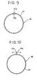
- the laminate 61 having the above-mentioned structure is wound up into a roll as shown in FIG. 9 and one edge 61a of the laminate 61 is placed on the other edge 61b thereof.
- the inner surface of the one edge 61a of the laminate i.e., the inner surface of the first film 62
- the outer surface of the other edge 61b thereof i.e. the outer surface of the fourth film 65
- the formation of the main body 11 is completed in this manner.
- the same kind of material is used for forming the first and fourth films 62 and 65 in order to improve the adhesive strength of the opposite edge portions 61a, 61b.
- the main body 11 may be formed by bending the opposite edge portions 61a, 61b of the laminate 61 so as to cause them to project outward in the diametrical direction of the main body 11 and joining the opposite edge portions 61a, 61b (on the inner surface of the fourth film 65) with each other by means of adhesive.
- the joined portions 61a, 61b, which project outward are pushed down in any one of directions, which are indicated by arrows in FIG. 10, and joined onto the outer surface of the main body 60 by means of adhesive.
- the joined portions of the main body 60 have a larger thickness than the remaining portion.
- the opposite edge portions of the same film, i.e., the fourth film 65 are joined with each other. Consequently, the formation of the first film 62 of the different material from that of the fourth film 65 will cause no problem.
- the other joining process may be adopted to form the main body 11 of the laminate 61.
- the opposite edges of the laminate 61 may be butted together and joined with each other by means of adhesive.
- the adhesive joining may be substituted by a fusion bonding joining.
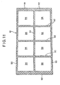
- FIG. 11 shows the laminate 61 in an expanded state. Portions where the joined portions 91 are formed are shown by cross-hatching in FIG. 11. As is clear from the figure, the joined portions 91 are composed of (i) portions that are formed so as to extend on the entire periphery of the front and rear ends of the main body 11, which is formed of the laminate 61, (ii) a portion that is formed so as to extend from the front end of the laminate 61 to the rear end thereof along the horizontal line, which passes through the center of the laminate 61, and (iii) portions (in this embodiment, three portions) that are formed so as to extend from the longitudinal upper edge of the laminate 61 to the longitudinal lower edge thereof at regular intervals.
- joined portions 91 are formed that have circular-shaped glued (joined) portions 92 circumferentially extending on the main body 11 and longitudinal glued (joined) portions 93 extending from the front end of the main body 11 to the rear end thereof in its longitudinal direction.
- the circular-shaped glued portions 92 are formed on the front and rear end of the main body and the middle portion thereof so as to provide the total number of five.
- the longitudinal edge of the laminate 61 is glued onto the other longitudinal edge thereof, with the result that the two longitudinal glued portions 93 are formed on the periphery of the main body 11 so as to separate from each other by the central angle of 180 degrees of the main body 11.
- Portions of the laminate 61 other than the circular-shaped glued portions 92 and the longitudinal glued portions 93 are remained as non-glued portions (i.e., non-joined portions) 94 in which the first film 62 and the second film 63 are not glued to each other.
- non-glued portions 94 the first and second films 62 and 63 can independently behave as the flexible film.
Landscapes
- Engineering & Computer Science (AREA)
- Mechanical Engineering (AREA)
- Manufacturing & Machinery (AREA)
- Tubes (AREA)
- Containers Having Bodies Formed In One Piece (AREA)
- Packages (AREA)
- Containers And Packaging Bodies Having A Special Means To Remove Contents (AREA)
Claims (5)
- Verfahren zur Herstellung eines Kunststoffbehälters, das die folgenden Schritte aufweist:wobei das Verfahren dadurch gekennzeichnet ist, dass:Vorbereiten einer Form (20) mit einem ersten Hohlraum (21), der so ausgebildet ist, dass er ein erstes geformtes Element (12) bildet, und einem zweiten Hohlraum (22), der so ausgebildet ist, dass er ein zweites geformtes Element (13) bildet;Bilden eines rohrförmigen Körpers (11) aus einem Kunststofflaminatfilm;Setzen des rohrförmigen Körpers (11) auf eine Außenfläche eines Dorns (23), der als Kern für die Form (20) dient;Anordnen des Dorns (23) in der Form (20); undEinspritzen von Kunstharzmaterial in einem geschmolzenen Zustand in den ersten und zweiten Hohlraum (21, 22) durch einen Einlege-Spritzvorgang, wobei das erste geformte Element (12) integral mit einer Außenfläche eines Endes des rohrförmigen Körpers (11) gebildet wird;wobei der Dorn (23) so angeordnet wird, dass ein Ende des rohrförmigen Körpers (11) sich an einer Innenseite des ersten Hohlraums (21) befindet und ein anderes Ende. davon sich an einer Außenseite des zweiten Hohlraums (22) befindet;der zweite Hohlraum (22) einen Außendurchmesser hat, der kleiner als ein Innendurchmesser des ersten Hohlraums ist, wobei die Hohlräume (21, 22) so ausgebildet sind, dass ein Innendurchmesser (R1) des ersten geformten Elements (12) größer ist als ein Außendurchmesser (R2) des zweiten geformten Elements;
wobei das Kunstharzmaterial so eingespritzt wird, dass das zweite geformte Element (13) integral mit einer Innenfläche des anderen Endes des rohrförmigen Körpers (11) gebildet wird. - Verfahren zum Herstellen eines Kunststoffbehälters nach Anspruch 1, das weiterhin folgenden Schritt aufweist:Ziehen des Dorns (23) aus der Form (20) nach dem Einlege-Spritzvorgang, wobei das erste geformte Element und das zweite geformte Element so ausgebildet sind, dass der Dorn (23) ohne Behinderung herausgezogen werden kann.
- Kunststoffbehälter, der aufweist:wobei der Kunststoffbehälter dadurch gekennzeichnet ist, dass:einen Hauptkörper (11), der aus einem Kunststofflaminatfilm in eine rohrförmige Form geformt ist,ein erstes geformtes Element (12), das an einer Außenfläche eines Endes des Hauptkörpers (11) durch einen Einlege-Spritzvorgang angefügt ist; undein zweites geformtes Element (13), das an einem anderen Ende des Hauptkörpers (11) durch den Einlege-Spritzvorgang angefügt ist;das erste geformte Element (12) ein Element mit großem Durchmesser von rohrförmiger Form ist; unddas zweite geformte Element ein Element mit kleinem Durchmesser ist, das an einer Innenfläche des Hauptkörpers (11) angefügt ist; wobeiein Innendurchmesser des ersten geformten Elements (13) größer ist als ein Außendurchmesser des zweiten geformten Elements.
- Behälter nach Anspruch 3, wobei
das erste geformte Element und das zweite geformte Element so ausgebildet sind, dass ein Dorn (23), der bei dem Einlege-Spritzvorgang verwendet wird, aus dem Hauptkörper (11) ohne Behinderung herausgezogen werden kann. - Behälter nach Anspruch 3 und 4, wobei
ein Greifabschnitt (15) an einer Außenfläche an einem unteren Ende des ersten geformten Elements gebildet ist.
Priority Applications (1)
| Application Number | Priority Date | Filing Date | Title |
|---|---|---|---|
| EP04011342A EP1462388B1 (de) | 1999-04-22 | 2000-03-14 | Mehrschichtiger Behälter |
Applications Claiming Priority (7)
| Application Number | Priority Date | Filing Date | Title |
|---|---|---|---|
| JP11461199A JP4063999B2 (ja) | 1999-04-22 | 1999-04-22 | 流動性物質用容器 |
| JP11461199 | 1999-04-22 | ||
| JP11464499 | 1999-04-22 | ||
| JP27184099 | 1999-09-27 | ||
| JP27184099A JP4297570B2 (ja) | 1999-09-27 | 1999-09-27 | 吐出装置およびカートリッジ装着治具 |
| JP33991499A JP2001149848A (ja) | 1999-11-30 | 1999-11-30 | 吐出装置 |
| JP33991499 | 1999-11-30 |
Related Child Applications (1)
| Application Number | Title | Priority Date | Filing Date |
|---|---|---|---|
| EP04011342A Division EP1462388B1 (de) | 1999-04-22 | 2000-03-14 | Mehrschichtiger Behälter |
Publications (3)
| Publication Number | Publication Date |
|---|---|
| EP1052182A2 EP1052182A2 (de) | 2000-11-15 |
| EP1052182A3 EP1052182A3 (de) | 2001-08-01 |
| EP1052182B1 true EP1052182B1 (de) | 2004-06-23 |
Family
ID=27312778
Family Applications (2)
| Application Number | Title | Priority Date | Filing Date |
|---|---|---|---|
| EP00302060A Expired - Lifetime EP1052182B1 (de) | 1999-04-22 | 2000-03-14 | Kunststoffbehälter und Verfahren zu seiner Herstellung |
| EP04011342A Expired - Lifetime EP1462388B1 (de) | 1999-04-22 | 2000-03-14 | Mehrschichtiger Behälter |
Family Applications After (1)
| Application Number | Title | Priority Date | Filing Date |
|---|---|---|---|
| EP04011342A Expired - Lifetime EP1462388B1 (de) | 1999-04-22 | 2000-03-14 | Mehrschichtiger Behälter |
Country Status (4)
| Country | Link |
|---|---|
| US (4) | US6334548B1 (de) |
| EP (2) | EP1052182B1 (de) |
| AT (1) | ATE269819T1 (de) |
| DE (2) | DE60011705T2 (de) |
Families Citing this family (42)
| Publication number | Priority date | Publication date | Assignee | Title |
|---|---|---|---|---|
| US6334548B1 (en) * | 1999-04-22 | 2002-01-01 | Hosokawa Yoko Co., Ltd. | Plastic container formed by insert-injection process |
| JP4275287B2 (ja) * | 2000-03-30 | 2009-06-10 | 株式会社細川洋行 | プラスチック容器 |
| US6796460B2 (en) * | 2001-06-14 | 2004-09-28 | Hosokawa Yoko Co., Ltd | Cartridge for fluid material and dispensing apparatus for such a cartridge |
| US20030015576A1 (en) * | 2001-07-03 | 2003-01-23 | Canino Paul Allen | Paper package with injection-molded plastic seams and handle |
| JP4110507B2 (ja) | 2001-11-22 | 2008-07-02 | シャープ化学工業株式会社 | 容器および押出器 |
| US7204381B2 (en) | 2001-12-31 | 2007-04-17 | Pechiney Plastic Packaging, Inc. | Waterguard tube |
| KR100984084B1 (ko) * | 2002-12-25 | 2010-09-30 | 혼다 기켄 고교 가부시키가이샤 | 사출 성형 방법 및 그 장치 |
| US7537136B2 (en) | 2003-06-11 | 2009-05-26 | Laurent Hechmati | Foldable air insulating sleeve |
| ATE321501T1 (de) * | 2003-06-18 | 2006-04-15 | 3M Espe Ag | Austragkartusche |
| DE10341256A1 (de) * | 2003-09-04 | 2004-07-01 | Klebchemie, M.G. Becker Gmbh & Co Kg | Klebefluidausgabevorrichtung |
| EP1829796A4 (de) * | 2004-12-01 | 2013-04-10 | Dow Corning Toray Co Ltd | Patrone für ein viskoseflüssigkeitsobjekt |
| DE102005009247A1 (de) * | 2005-02-25 | 2006-08-31 | Bruno Castellucci | Kompakte Vorrichtung zum Verfugen |
| US20080032007A1 (en) * | 2006-08-03 | 2008-02-07 | Scarola Leonard S | EVOH barrier layer for particulate coffee |
| US20080299263A1 (en) * | 2007-05-18 | 2008-12-04 | Robert David Piotrowski | Coffee package which communicates usage indicia |
| US20080286418A1 (en) * | 2007-05-18 | 2008-11-20 | Robert David Piotrowski | Coffee package which communicates usage indicia |
| US20080286417A1 (en) * | 2007-05-18 | 2008-11-20 | Robert David Piotrowski | Method of displaying coffee packages in an array which communicate usage indicia |
| FR2922532A1 (fr) * | 2007-10-22 | 2009-04-24 | Lir France Soc Par Actions Sim | Distributeur de produit liquide, semi-solide de type cosmetique, pharmaceutique ou parapharmaceutique |
| DE102008005743A1 (de) * | 2008-01-23 | 2009-08-06 | Heraeus Kulzer Gmbh | Vorrichtung zur Lagerung von fluiden Komponenten für den dentalen Bereich |
| DE102008063502A1 (de) * | 2008-12-17 | 2010-06-24 | Fischbach Kg Kunststoff-Technik | Auspresswerkzeug |
| EP2198978A1 (de) * | 2008-12-18 | 2010-06-23 | Sika Technology AG | Dispensierwerkzeug für pastöse Substanzen |
| US20100227094A1 (en) * | 2009-03-09 | 2010-09-09 | Ipl, Inc. | Oxygen barrier molded container and method for production thereof |
| IT1394293B1 (it) * | 2009-05-07 | 2012-06-06 | Zanfrini | Contenitore monouso per rifiuti per termodistruzione |
| EP2560888B1 (de) * | 2010-04-19 | 2017-05-31 | Sulzer Mixpac AG | Stehfähige kartusche, austragsvorrichtung für eine solche sowie verfahren zur verwendung der kartusche |
| KR101968608B1 (ko) * | 2011-10-17 | 2019-04-12 | 술저 믹스팩 아게 | 카트리지 및 다성분 카트리지 |
| KR102069165B1 (ko) * | 2011-10-17 | 2020-01-22 | 술저 믹스팩 아게 | 카트리지, 카트리지를 생산하기 위한 방법, 및 다성분 카트리지 |
| WO2013142602A1 (en) | 2012-03-20 | 2013-09-26 | Berry Plastics Corporation | Package |
| US9145251B2 (en) | 2012-10-26 | 2015-09-29 | Berry Plastics Corporation | Package |
| US9597706B2 (en) | 2013-03-15 | 2017-03-21 | Rooftop Research, Llc | Container and substance dispensing system |
| US9731317B2 (en) | 2014-10-15 | 2017-08-15 | Sonoco Development, Inc. | Device for holding and dispensing viscous material |
| US10532872B2 (en) | 2014-12-08 | 2020-01-14 | Berry Plastics Corporation | Package |
| EP3181244A1 (de) | 2015-12-18 | 2017-06-21 | HILTI Aktiengesellschaft | Baugruppe aus einem foliengebinde und einer auspressvorrichtung sowie foliengebinde |
| EP3263483A1 (de) | 2016-07-01 | 2018-01-03 | Sulzer Mixpac AG | Kartusche, kern, form und verfahren zur herstellung einer kartusche |
| ES2698549T3 (es) | 2016-07-01 | 2019-02-05 | Sulzer Mixpac Ag | Cartucho, núcleo, molde y método de fabricación de un cartucho |
| CN109641235A (zh) * | 2016-08-31 | 2019-04-16 | 诺信公司 | 多部件柔性包装分配歧管和系统 |
| US10596591B2 (en) * | 2017-01-04 | 2020-03-24 | Red Devil Inc. | Material dispensing system and method |
| WO2020069784A1 (en) | 2018-10-02 | 2020-04-09 | Sulzer Mixpac Ag | Cartridge, method of manufacturing a cartridge, dispensing assembly and method of assembling a dispensing assembly |
| US10870127B2 (en) | 2018-10-02 | 2020-12-22 | Sulzer Mixpac Ag | Cartridge for a mixing and dispensing system |
| US10434528B1 (en) | 2018-10-02 | 2019-10-08 | Sulzer Mixpac Ag | Cartridge, dispensing assembly and method of manufacturing a cartridge |
| US10906702B2 (en) | 2018-10-02 | 2021-02-02 | Sulzer Mixpac Ag | Cartridge, method of manufacturing a cartridge, dispensing assembly and method of assembling a dispensing assembly |
| EP3826940B1 (de) | 2018-10-02 | 2024-04-10 | medmix Switzerland AG | Kartusche, abgabeanordnung und verfahren zur herstellung einer kartusche |
| EP3834948A1 (de) * | 2019-12-13 | 2021-06-16 | Hilti Aktiengesellschaft | Verfahren zur herstellung einer kartusche und kartusche |
| US11772851B2 (en) | 2021-06-21 | 2023-10-03 | Medmix Switzerland Ag | Liquid applicator |
Family Cites Families (43)
| Publication number | Priority date | Publication date | Assignee | Title |
|---|---|---|---|---|
| US2561825A (en) * | 1947-08-08 | 1951-07-24 | William A Sherbondy | Dispensing device for calking material and the like |
| US2794473A (en) * | 1954-01-26 | 1957-06-04 | Donald R Williams | Semi-flexible receptacle |
| US2853209A (en) * | 1955-01-13 | 1958-09-23 | Phillips Petroleum Co | Container |
| US2833451A (en) * | 1957-01-17 | 1958-05-06 | William A Sherbondy | Caulking gun and cartridge therefor |
| US2941699A (en) * | 1957-04-08 | 1960-06-21 | R C Can Co | Flexible closure and plunger for cartridge-container |
| US2955728A (en) * | 1958-03-04 | 1960-10-11 | Louis A Macklanburg | Calking load ejector cup |
| US3250443A (en) * | 1964-12-21 | 1966-05-10 | Gen Electric | Dispensing cartridge plunger |
| US3315847A (en) * | 1965-05-13 | 1967-04-25 | Pyles Ind Inc | Plunger |
| US3288333A (en) * | 1965-09-21 | 1966-11-29 | Jr John Valk | Caulking gun cartridtge |
| US3378175A (en) * | 1966-02-03 | 1968-04-16 | Container Corp | Piston for material dispensing gun cartridge |
| US3476852A (en) * | 1967-07-14 | 1969-11-04 | Borg Warner | Method of molding thermoplastic articles |
| NL157268C (de) * | 1968-03-20 | |||
| US3836063A (en) * | 1971-02-03 | 1974-09-17 | Airfix Ind Ltd | Production of containers |
| US3707693A (en) * | 1971-04-19 | 1972-12-26 | Precision Paper Tube Co | Variable inductor and method |
| US3734393A (en) * | 1971-07-29 | 1973-05-22 | Clevepak Corp | Wide mouth tubular container construction |
| GB1462856A (en) * | 1973-02-12 | 1977-01-26 | Airfix Ind Ltd | Production of composite containers |
| US4065034A (en) * | 1976-07-30 | 1977-12-27 | Cities Service Company | Gun-type dispenser for heat softenable adhesive or sealant compounds |
| US4629598A (en) * | 1979-04-10 | 1986-12-16 | Tri-Tech Systems International, Inc. | Method for forming plastic bottle with integral handle |
| US4252256A (en) * | 1979-07-13 | 1981-02-24 | Walsh Edward E | Compressible drinking apparatus |
| AU537385B2 (en) * | 1979-07-19 | 1984-06-21 | Yoshino Kogyosho Co., Ltd. | Moulding elongated parison with integral plug |
| JPS5651265A (en) | 1979-10-02 | 1981-05-08 | Nitsushiri:Kk | Application of sealing material |
| DE3279531D1 (en) | 1981-05-14 | 1989-04-20 | Hoechst Ag | Upside open box-like container comprising a wall of plastics film, and method for making same |
| JPS5938038A (ja) | 1982-08-27 | 1984-03-01 | Dainippon Printing Co Ltd | ペースト状食品の充填包装に使用する半製品の複合容器の製造方法 |
| JPS5939528A (ja) * | 1982-08-31 | 1984-03-03 | Katashi Aoki | 複合パリソンの射出成形方法及び装置 |
| US4527699A (en) * | 1982-09-16 | 1985-07-09 | Nippon Light Metal Co., Ltd. | Vessel for storing liquid |
| US4678107A (en) * | 1985-08-02 | 1987-07-07 | Mark L. Anderson | Dripless dispenser for liquids and viscous fluids |
| JPS62181130A (ja) * | 1986-02-06 | 1987-08-08 | Nissei Ee S B Kikai Kk | 把手付き中空容器の成形方法 |
| US5057266A (en) * | 1988-07-21 | 1991-10-15 | Sabel Plastechs, Inc. | Method of making a hollow polyethylene terephthalate blow molded article with an integral external projection such as a handle |
| US5058801A (en) * | 1990-04-16 | 1991-10-22 | Cin-Made Corporation | Composite can |
| JPH0741648B2 (ja) * | 1990-12-28 | 1995-05-10 | 日プラ株式会社 | 糸底付きインモールドラベリング容器及びその製造方法 |
| JP2643109B2 (ja) | 1991-04-19 | 1997-08-20 | 日本ビクター株式会社 | 無線通信機の空チャンネル移行装置 |
| US5270092A (en) * | 1991-08-08 | 1993-12-14 | The Regents, University Of California | Gas filled panel insulation |
| EP0550776B1 (de) * | 1992-01-10 | 1997-04-09 | Excell Corporation | Verfahren zur Herstellung eines Hohlgegenstandes aus Kunststoff mit einem radialen Vorsprung |
| GB9213852D0 (en) * | 1992-06-30 | 1992-08-12 | Dow Corning Gmbh | Sealant cartridge |
| PH31484A (en) | 1992-12-22 | 1998-11-03 | Hosokawa Yoko Kk | Container, method of manufacturing the same and installation jig for cartridge container for d18scharge gun. |
| US5433337A (en) * | 1994-01-28 | 1995-07-18 | Sterling Products, Inc. | Large drink container to fit vehicle cup holders |
| US5733258A (en) * | 1995-09-22 | 1998-03-31 | Lane; Donovan R. | Livestock biological and vaccine handling system to include pistol grip syringe and cartridge |
| US5965081A (en) * | 1996-05-16 | 1999-10-12 | The Coca-Cola Company | Method of making side-gated preforms for use in blow molding plastic bottles |
| US5851471A (en) * | 1996-05-16 | 1998-12-22 | The Coca-Cola Company | Method for injection molding a multi-layer preform for use in blow molding a plastic bottle |
| US6322738B1 (en) * | 1997-07-24 | 2001-11-27 | Husky Injection Molding Systems Ltd. | Method of injection over-molding articles |
| GB2337088A (en) * | 1998-02-18 | 1999-11-10 | P C Cox Limited | A dispenser for viscous materials |
| US6155463A (en) * | 1998-10-27 | 2000-12-05 | Z-Pro International, Inc. | Viscous material dispenser |
| US6334548B1 (en) * | 1999-04-22 | 2002-01-01 | Hosokawa Yoko Co., Ltd. | Plastic container formed by insert-injection process |
-
2000
- 2000-03-13 US US09/524,545 patent/US6334548B1/en not_active Expired - Lifetime
- 2000-03-14 DE DE60011705T patent/DE60011705T2/de not_active Expired - Lifetime
- 2000-03-14 DE DE60034604T patent/DE60034604T2/de not_active Expired - Lifetime
- 2000-03-14 EP EP00302060A patent/EP1052182B1/de not_active Expired - Lifetime
- 2000-03-14 AT AT00302060T patent/ATE269819T1/de not_active IP Right Cessation
- 2000-03-14 EP EP04011342A patent/EP1462388B1/de not_active Expired - Lifetime
-
2001
- 2001-11-13 US US09/986,888 patent/US6521158B2/en not_active Expired - Lifetime
-
2002
- 2002-12-27 US US10/329,495 patent/US6736290B2/en not_active Expired - Lifetime
- 2002-12-27 US US10/329,496 patent/US20030091773A1/en not_active Abandoned
Also Published As
| Publication number | Publication date |
|---|---|
| US6334548B1 (en) | 2002-01-01 |
| HK1028759A1 (en) | 2001-03-02 |
| EP1052182A2 (de) | 2000-11-15 |
| DE60034604D1 (de) | 2007-06-06 |
| US20020056726A1 (en) | 2002-05-16 |
| US6736290B2 (en) | 2004-05-18 |
| DE60034604T2 (de) | 2008-01-10 |
| US20030089736A1 (en) | 2003-05-15 |
| EP1052182A3 (de) | 2001-08-01 |
| US6521158B2 (en) | 2003-02-18 |
| DE60011705D1 (de) | 2004-07-29 |
| US20030091773A1 (en) | 2003-05-15 |
| DE60011705T2 (de) | 2005-08-25 |
| EP1462388A1 (de) | 2004-09-29 |
| EP1462388B1 (de) | 2007-04-25 |
| ATE269819T1 (de) | 2004-07-15 |
Similar Documents
| Publication | Publication Date | Title |
|---|---|---|
| EP1052182B1 (de) | Kunststoffbehälter und Verfahren zu seiner Herstellung | |
| KR0185216B1 (ko) | 내부용기 및 외부용기를 구비한 복합용기 | |
| EP1637457B1 (de) | Etikettensystem im werkzeug für kunststoffbehälter | |
| EP0305976B1 (de) | Leicht zu öffnender versiegelter Behälter | |
| EP0825123B1 (de) | Verpackungsbehälter und verfahren zu dessen herstellung | |
| US4948006A (en) | Container with metallic cover and method of manufacturing the same | |
| US4735665A (en) | Method for manufacturing a can-like container | |
| JPH04267727A (ja) | 多層成形容器及びその製造方法 | |
| US5779841A (en) | Container having ear and a method for manufacturing the same | |
| EP2045195A1 (de) | Versiegelter Behälter und Verfahren zu dessen Herstellung | |
| WO2007017979A1 (ja) | 注出口部付き袋 | |
| US20050238264A1 (en) | Gusset bag and method of producing the same | |
| JP3952145B2 (ja) | 自立袋及びその製造方法 | |
| JP4220044B2 (ja) | 電子レンジ用射出成形容器 | |
| JP3772436B2 (ja) | 容器になるシートへの中空状付属品の取付構造 | |
| JP4638789B2 (ja) | 注出口部付き袋 | |
| EP0786414A1 (de) | Verbundbehälter | |
| JP3998798B2 (ja) | インモ−ルドラベリング成形容器 | |
| HK1028759B (en) | Plastic container and method for manufacturing same | |
| EP0796171B1 (de) | Verfahren zum herstellen eines verpackungsbehälters | |
| JP3336352B2 (ja) | 合成樹脂製壜体とその成形方法 | |
| JPH08268470A (ja) | 複合容器 | |
| JP4357851B2 (ja) | 複合容器 | |
| JP2000103428A (ja) | プラスチック容器およびプラスチック容器の製造方法 | |
| JP2001019038A (ja) | バックインボックス用内袋およびその製造方法 |
Legal Events
| Date | Code | Title | Description |
|---|---|---|---|
| PUAI | Public reference made under article 153(3) epc to a published international application that has entered the european phase |
Free format text: ORIGINAL CODE: 0009012 |
|
| AK | Designated contracting states |
Kind code of ref document: A2 Designated state(s): AT BE CH CY DE DK ES FI FR GB GR IE IT LI LU MC NL PT SE |
|
| AX | Request for extension of the european patent |
Free format text: AL;LT;LV;MK;RO;SI |
|
| RIC1 | Information provided on ipc code assigned before grant |
Free format text: 7B 65D 33/02 A, 7B 05C 17/01 B, 7B 65D 83/00 B, 7B 29C 45/14 B |
|
| PUAL | Search report despatched |
Free format text: ORIGINAL CODE: 0009013 |
|
| AK | Designated contracting states |
Kind code of ref document: A3 Designated state(s): AT BE CH CY DE DK ES FI FR GB GR IE IT LI LU MC NL PT SE |
|
| AX | Request for extension of the european patent |
Free format text: AL;LT;LV;MK;RO;SI |
|
| 17P | Request for examination filed |
Effective date: 20010706 |
|
| AKX | Designation fees paid |
Free format text: AT BE CH CY DE DK ES FI FR GB GR IE IT LI LU MC NL PT SE |
|
| 17Q | First examination report despatched |
Effective date: 20021115 |
|
| RTI1 | Title (correction) |
Free format text: PLASTIC CONTAINER AND METHOD FOR MANUFACTURING SAME |
|
| RTI1 | Title (correction) |
Free format text: PLASTIC CONTAINER AND METHOD FOR MANUFACTURING SAME |
|
| GRAP | Despatch of communication of intention to grant a patent |
Free format text: ORIGINAL CODE: EPIDOSNIGR1 |
|
| GRAS | Grant fee paid |
Free format text: ORIGINAL CODE: EPIDOSNIGR3 |
|
| GRAA | (expected) grant |
Free format text: ORIGINAL CODE: 0009210 |
|
| AK | Designated contracting states |
Kind code of ref document: B1 Designated state(s): AT BE CH CY DE DK ES FI FR GB GR IE IT LI LU MC NL PT SE |
|
| PG25 | Lapsed in a contracting state [announced via postgrant information from national office to epo] |
Ref country code: AT Free format text: LAPSE BECAUSE OF FAILURE TO SUBMIT A TRANSLATION OF THE DESCRIPTION OR TO PAY THE FEE WITHIN THE PRESCRIBED TIME-LIMIT Effective date: 20040623 Ref country code: FI Free format text: LAPSE BECAUSE OF FAILURE TO SUBMIT A TRANSLATION OF THE DESCRIPTION OR TO PAY THE FEE WITHIN THE PRESCRIBED TIME-LIMIT Effective date: 20040623 |
|
| REG | Reference to a national code |
Ref country code: GB Ref legal event code: FG4D |
|
| REG | Reference to a national code |
Ref country code: CH Ref legal event code: EP |
|
| REG | Reference to a national code |
Ref country code: IE Ref legal event code: FG4D |
|
| REF | Corresponds to: |
Ref document number: 60011705 Country of ref document: DE Date of ref document: 20040729 Kind code of ref document: P |
|
| PG25 | Lapsed in a contracting state [announced via postgrant information from national office to epo] |
Ref country code: DK Free format text: LAPSE BECAUSE OF FAILURE TO SUBMIT A TRANSLATION OF THE DESCRIPTION OR TO PAY THE FEE WITHIN THE PRESCRIBED TIME-LIMIT Effective date: 20040923 Ref country code: GR Free format text: LAPSE BECAUSE OF FAILURE TO SUBMIT A TRANSLATION OF THE DESCRIPTION OR TO PAY THE FEE WITHIN THE PRESCRIBED TIME-LIMIT Effective date: 20040923 Ref country code: SE Free format text: LAPSE BECAUSE OF FAILURE TO SUBMIT A TRANSLATION OF THE DESCRIPTION OR TO PAY THE FEE WITHIN THE PRESCRIBED TIME-LIMIT Effective date: 20040923 |
|
| PG25 | Lapsed in a contracting state [announced via postgrant information from national office to epo] |
Ref country code: ES Free format text: LAPSE BECAUSE OF FAILURE TO SUBMIT A TRANSLATION OF THE DESCRIPTION OR TO PAY THE FEE WITHIN THE PRESCRIBED TIME-LIMIT Effective date: 20041004 |
|
| REG | Reference to a national code |
Ref country code: CH Ref legal event code: NV Representative=s name: R. A. EGLI & CO. PATENTANWAELTE |
|
| REG | Reference to a national code |
Ref country code: HK Ref legal event code: GR Ref document number: 1028759 Country of ref document: HK |
|
| PG25 | Lapsed in a contracting state [announced via postgrant information from national office to epo] |
Ref country code: IE Free format text: LAPSE BECAUSE OF NON-PAYMENT OF DUE FEES Effective date: 20050314 Ref country code: IT Free format text: LAPSE BECAUSE OF NON-PAYMENT OF DUE FEES Effective date: 20050314 Ref country code: CY Free format text: LAPSE BECAUSE OF FAILURE TO SUBMIT A TRANSLATION OF THE DESCRIPTION OR TO PAY THE FEE WITHIN THE PRESCRIBED TIME-LIMIT Effective date: 20050314 |
|
| ET | Fr: translation filed | ||
| PG25 | Lapsed in a contracting state [announced via postgrant information from national office to epo] |
Ref country code: CH Free format text: LAPSE BECAUSE OF NON-PAYMENT OF DUE FEES Effective date: 20050331 Ref country code: BE Free format text: LAPSE BECAUSE OF NON-PAYMENT OF DUE FEES Effective date: 20050331 Ref country code: MC Free format text: LAPSE BECAUSE OF NON-PAYMENT OF DUE FEES Effective date: 20050331 Ref country code: LI Free format text: LAPSE BECAUSE OF NON-PAYMENT OF DUE FEES Effective date: 20050331 |
|
| PLBE | No opposition filed within time limit |
Free format text: ORIGINAL CODE: 0009261 |
|
| STAA | Information on the status of an ep patent application or granted ep patent |
Free format text: STATUS: NO OPPOSITION FILED WITHIN TIME LIMIT |
|
| 26N | No opposition filed |
Effective date: 20050324 |
|
| BERE | Be: lapsed |
Owner name: *HOSOKAWA YOKO CO. LTD Effective date: 20050331 |
|
| PG25 | Lapsed in a contracting state [announced via postgrant information from national office to epo] |
Ref country code: NL Free format text: LAPSE BECAUSE OF NON-PAYMENT OF DUE FEES Effective date: 20051001 |
|
| REG | Reference to a national code |
Ref country code: CH Ref legal event code: PL |
|
| NLV4 | Nl: lapsed or anulled due to non-payment of the annual fee |
Effective date: 20051001 |
|
| REG | Reference to a national code |
Ref country code: IE Ref legal event code: MM4A |
|
| BERE | Be: lapsed |
Owner name: *HOSOKAWA YOKO CO. LTD Effective date: 20050331 |
|
| PG25 | Lapsed in a contracting state [announced via postgrant information from national office to epo] |
Ref country code: PT Free format text: LAPSE BECAUSE OF NON-PAYMENT OF DUE FEES Effective date: 20041123 |
|
| REG | Reference to a national code |
Ref country code: FR Ref legal event code: PLFP Year of fee payment: 16 |
|
| PGFP | Annual fee paid to national office [announced via postgrant information from national office to epo] |
Ref country code: DE Payment date: 20150310 Year of fee payment: 16 |
|
| PGFP | Annual fee paid to national office [announced via postgrant information from national office to epo] |
Ref country code: GB Payment date: 20150311 Year of fee payment: 16 Ref country code: FR Payment date: 20150309 Year of fee payment: 16 |
|
| REG | Reference to a national code |
Ref country code: DE Ref legal event code: R119 Ref document number: 60011705 Country of ref document: DE |
|
| GBPC | Gb: european patent ceased through non-payment of renewal fee |
Effective date: 20160314 |
|
| REG | Reference to a national code |
Ref country code: FR Ref legal event code: ST Effective date: 20161130 |
|
| PG25 | Lapsed in a contracting state [announced via postgrant information from national office to epo] |
Ref country code: FR Free format text: LAPSE BECAUSE OF NON-PAYMENT OF DUE FEES Effective date: 20160331 Ref country code: DE Free format text: LAPSE BECAUSE OF NON-PAYMENT OF DUE FEES Effective date: 20161001 Ref country code: GB Free format text: LAPSE BECAUSE OF NON-PAYMENT OF DUE FEES Effective date: 20160314 |