EP1052163A2 - Anhänger mit einem selbsttragenden Aufbau aus Leichtmetall - Google Patents
Anhänger mit einem selbsttragenden Aufbau aus Leichtmetall Download PDFInfo
- Publication number
- EP1052163A2 EP1052163A2 EP00109774A EP00109774A EP1052163A2 EP 1052163 A2 EP1052163 A2 EP 1052163A2 EP 00109774 A EP00109774 A EP 00109774A EP 00109774 A EP00109774 A EP 00109774A EP 1052163 A2 EP1052163 A2 EP 1052163A2
- Authority
- EP
- European Patent Office
- Prior art keywords
- base plate
- trailer
- plate
- trailer according
- wheels
- Prior art date
- Legal status (The legal status is an assumption and is not a legal conclusion. Google has not performed a legal analysis and makes no representation as to the accuracy of the status listed.)
- Granted
Links
Images


Classifications
-
- B—PERFORMING OPERATIONS; TRANSPORTING
- B62—LAND VEHICLES FOR TRAVELLING OTHERWISE THAN ON RAILS
- B62D—MOTOR VEHICLES; TRAILERS
- B62D63/00—Motor vehicles or trailers not otherwise provided for
- B62D63/06—Trailers
Definitions
- the present invention relates to a trailer one consisting of a floor, four walls and a roof, self - supporting structure made of light metal and with two axles with wheels, the front axle one Drawbar and by means of one under the front Part of the structure arranged slewing ring is steerable.
- Task to a trailer of the type mentioned create that avoids the disadvantages listed and where possible, especially given the total height high cargo space is achieved without losing stability the structure is impaired, and in which the Driving characteristics, especially when cornering, safe are.
- the trailer according to the invention is a low Height in the area of the connection of the slewing ring with reached the construction, so that the amount obtained here Loading space height is fully beneficial without the total height of the trailer must be enlarged.
- the forces occurring between the front wheels and the Structure transferred and received without damage because of the base plate is sufficiently inherently stable because it has three Sides immediately with the corresponding walls of the structure is connected and because on the fourth, rear side the bottom plate is provided with a cross profile in turn at its ends directly with the side walls the construction is connected.
- the length of the base plate should be as small as possible be held, only so long that the No wheels regardless of their steering angle can collide with the cross section.
- the steering and Suspension movements of the front wheels are thereby the cross section is not hindered, so no restrictions occur in the function.
- the slewing ring can immediately or with the insertion of an intermediate layer be connected to the underside of the base plate.
- the base plate is one single-layer plate, the thickness of which corresponds to the static and dynamic requirements is selected.
- the base plate can be at least in one Part of their surface extension multi-layer plate be what the advantage of a high load capacity with reduced Offers weight.
- a training of the last mentioned execution of the Base plate provides that the base plate in one in Middle area of the trailer running in two layers formed from an upper and a lower plate is that run a short distance from each other and are connected to one another via ribs or webs, wherein the width of the central area is smaller than the inner one There is free clearance between the front wheels and the bottom plate in the areas on both sides of the middle area is two-layer with a smaller overall height or one-layer and flush on the upper side with the top of the central area is executed.
- the base plate is particularly stable; at the same time it is in the areas when driving straight ahead or small steering angle of the front wheels over this lie, made thinner, so that here a larger space is available for suspension movements.
- the base plate preferably consists of Steel; alternatively, it can also consist of a strength steel equivalent or better material be made.
- the front wheels can also create the Base plate in the front axle in the straight-ahead driving position Areas above the front wheels at least one section or at least one Show area with reduced plate thickness.
- the invention further provides that the bottom plate on the underside in the of the front wheels during their steering movements not swept areas one or more Reinforcement rings arranged concentrically to the slewing ring and / or one or more reinforcement strips and / or has profiles. In this way, the bottom plate are stiffened and reinforced without the Front wheels in their steering and suspension movements be hindered.
- the bottom plate along its longitudinal central axis in front of and / or behind the slewing ring with (each) one a duct for electrical and compressed air lines and other supply lines forming oblong surfaces
- Protective hood is equipped.
- the protective hood disturbs the steering and Front wheel suspension movements when driving straight ahead and moderate cornering; with a very strong drawbar impact the wheels reach approximately 90 ° in the area of the protective hood or protective hoods, however Such large steering angles only occur when maneuvering on which because of the very slow speed practically no suspension movements occur.
- wearing the protective hood or wearing Protective covers still increase the static somewhat and dynamic load-bearing capacity of the base plate, so that two functions can be achieved simultaneously.
- the base plate is expediently arranged so that its Top with the top of the rest of the bottom of the body is aligned so that a stepless load floor is reached becomes.
- the bottom plate on the top on their surface area inside the structure with a intended use of the trailer corresponding, e.g. anti-slip or smooth or other suitable surface or is executed.
- the rest of the load floor is practical provided or finished with the same surface, so that a uniform cargo floor inside the
- the aforementioned surface can be, for example, by a sheet metal attached to the top of the base plate with a correspondingly designed upper side.
- the area of the floor that is not formed by the base plate the structure consists, as in known structures usual, for example from cross-laid profiles or Sheet metal or the like.
- liquid-tight tub can also a sheet of metal attached to the floor at its four Edges, except for the area of door openings, be folded upwards.
- Trailer 1 has a self-supporting structure 10 Light metal consisting of four walls 11, 11 ', one floor 12 and a roof 13 is formed.
- the Trailer 1 a front axle 4 with front wheels 40 and a rear axle 5 with rear wheels 50.
- the front axle 4 is by means of a slewing ring 3 around a vertical Axis 30 swiveling.
- Drawbar 41 is the trailer 1 with a towing vehicle detachable.
- the bottom 12 is in the front part of the trailer 1 by a relatively thin but load-bearing Metal base plate 2 replaced, the base plate 2 and the rest of the bottom 12 approximately flush with one another on the upper side are aligned.
- the bottom plate 2 has in Difference to the rest of the floor 12 a higher stability and load capacity to the forces occurring between Take up front axle 4 and body 10 without damage and forward to be able to.
- the base plate 2 is preferably made of steel or of another, same or higher Stability and strength requirements Material.
- the top is for the convenient transfer of forces the bottom plate 2 at its front edge under the front wall 11 of the body 10.
- the two side Edges of the base plate 2 lie under the side walls 11 'of the structure 10.
- This cross section 20 lies with his lateral ends below the lateral walls 11 ' of the structure 10 and is connected there to the walls 11 ', so that at the rear edge of the base plate 2 forces occurring through the cross section 20 to its side ends and from there into the side walls 11 'of the structure 10 are passed.
- the one shown here is required Construction of the trailer 1 on the underside the base plate 2 no additional stiffeners or reinforcement profiles in the swivel range of the front wheels, as they are in the form of I, C or rectangular profiles etc. with previously known trailers under one continuous base in body made of light metal were common and required.
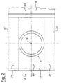
- Figure 2 of the drawing shows a view from below to a first version of the base plate 2, to which the rest to the right, only a small part shown bottom 12 of the trailer connects.
- the turntable 3 can be seen in whose center is perpendicular to the plane of the drawing
- Pivot axis 30 extends around which the one not shown here Front axle of the trailer is pivotable.
- the base plate 2 is in the embodiment shown here with three different areas 21, 22, of which a central area seen in the longitudinal direction 22 is formed in two layers.
- this area 22 the base plate 2 consists of two layers that are together connected by ribs or webs not visible here are; also a one-piece design as a continuous Profile is conceivable.
- the width of the two-ply Area 22 is as large as the maximum outer diameter the slewing ring 3; the rest of the Base plate 2 occupy the two outer regions 21, under which the front wheels 40, not shown here run when driving straight ahead or with a small steering angle. Since the material thickness of the plate 2 is lower here, there is for the bikes located there a larger free space for suspension movements, so that the Base plate 2 does not occur on the front wheels 40.
- the base plate 2 completed by the cross section 20.
- the bottom plate 2 is on its side edges and on its front edge just below the walls 11, 11 'of the structure 10 and that it is at its rear Edge supported by the stable cross section 20 that is in turn with its frontal areas below the side walls 11 '.
- FIG. 3 A second embodiment of the base plate 2 is shown in FIG. 3 in the same representation as shown in Figure 2.
- the base plate is 2 designed and worn over its entire surface in its center again the turntable 3, the center of which forms the pivot axis 30. 3 are at the top two front wheels 40 as twin wheels on one Shown side of the axle, the two wheels 40th have a certain distance from each other. Divided by two dashed circles are the possible positions of the Center of the wheels when swiveling the front axle 4 shown about the pivot axis 30. Concentric to Slewing ring 3 is exactly in the area between the twin wheels 40 a reinforcing ring 24 is provided, the attached to the base plate, e.g.
- the base plate 2 is welded on and which braces the base plate 2 and can withstand higher loads does without the suspension and steering movements of the wheels Restrict 40.
- the base plate 2 is also located here their side edges and their front edge under the side walls 11 'and the front wall 11 of the structure 10; on the far right in Figure 3 is a small one Part of the rest of the bottom 12 of the structure 10 can be seen, the extends to the right of the cross section 20 to the rear.
- FIG. 4 of the drawing finally shows an embodiment the base plate 2, in which several additional design features are shown, individually or in combination can be present together.
- the bottom plate 2 is here again rectangular in its basic form and executed in one layer and is to the rear, i.e. in the drawing to the right, completed by the cross section 20, behind which is still a small part of the rest Bottom 12 of the structure 10 can be seen.
- the base plate 2 is here again with the slewing ring 3 the pivot axis 30 at its center.
- FIG. 4 Another example of an additional feature is in Figure 4 bottom right on the base plate 2 in one Corner area of diagonally extending reinforcement strips 25 shown, which forms a stiffening of the base plate 2 and is arranged in an area where he the Steering and suspension movements of the front wheels 40 are not can hinder.
- FIG. 4 shows parallel to the longitudinal central axis the base plate 2, two protective hoods 27, which are elongated-flat and whose interior unites Duct for laying compressed air lines and electrical cables and other supply lines etc., to supply a brake system and lighting system and other equipment of the trailer 1 are needed.
- the protective hoods 27 are so flat executed that the front wheels 40 at a large steering angle in the range of about 90 ° still under the protective hoods 27 fit through; a suspension travel is at one such a large steering angle is practically not required, so that there is relatively little clearance between the front wheels 40 and protective hoods 27 is sufficient.
- the protective hoods 27 When driving straight ahead or moderate cornering of the trailer 1 the protective hoods 27 in an area in which the Do not move wheels 40, so that through the protective hoods 27th the suspension travel is then not restricted.
Landscapes
- Engineering & Computer Science (AREA)
- Chemical & Material Sciences (AREA)
- Combustion & Propulsion (AREA)
- Transportation (AREA)
- Mechanical Engineering (AREA)
- Body Structure For Vehicles (AREA)
- Vehicle Body Suspensions (AREA)
- Vessels And Coating Films For Discharge Lamps (AREA)
Abstract
- Der vordere Teil des Bodens (12) ist durch eine dünne tragende Bodenplatte (2), vorzugsweise aus Stahl, gebildet oder unterlegt, an deren Unterseite der obere Teil (32) des Drehkranzes (3) unmittelbar oder mittels einer Zwischenlage angebracht ist.
- Die Bodenplatte (2) ist an ihrer Vorderkante mit der vorderen Wand (11) und an ihren zwei Seitenkanten mit dem vorderen Bereich der beiden Seitenwände (11') verbunden.
- Die Bodenplatte (2) ist an ihrem hinter dem Bewegungsbereich der Vorderachse (4) mit einem Querträger (20) ausgeführt, der mit seinen Enden mit den beiden Seitenwänden (11') verbunden ist und der im wesentlichen nur nach unten über die Bodenplatte (2) vorragt.
Description
- daß der vordere Teil des Bodens durch eine dünne tragende Bodenplatte, vorzugsweise aus Stahl, gebildet oder unterlegt ist, an deren Unterseite der obere Teil des Drehkranzes unmittelbar oder mittels einer Zwischenlage angebracht ist,
- daß die Bodenplatte an ihrer Vorderkante mit der vorderen Wand und an ihren zwei Seitenkanten mit dem vorderen Bereich der beiden Seitenwände verbunden ist und
- daß die Bodenplatte an ihrem hinter dem Bewegungsbereich der Vorderachse und der daran gelagerten Räder liegenden hinteren Bereich als oder mit einem keine tragende Funktion für die Hinterachse und/oder für den hinteren Bodenteil aufweisenden Querträger ausgeführt ist, der mit seinen Enden mit den beiden Seitenwänden verbunden ist und der im wesentlichen nur nach unten über die Bodenplatte vorragt.
- Figur 1
- einen Anhänger in Seitenansicht in einer schematischen Darstellung, teils im Vertikalschnitt,
- Figur 2
- eine Bodenplatte als Teil des Anhängers in Unteransicht in einer ersten Ausführung,
- Figur 3
- die Bodenplatte in gleicher Darstellungsweise in einer zweiten Ausführung und
- Figur 4
- die Bodenplatte in einer dritten Ausführung, ebenfalls in Unteransicht.
Claims (10)
- Anhänger (1) mit einem aus einem Boden (12), vier Wänden (11, 11') und einem Dach (13) bestehenden, selbsttragenden Aufbau (10) aus Leichtmetall und mit zwei Achsen (4, 5) mit Rädern (40, 50), wobei die Vorderachse (4) eine Deichsel (41) aufweist und mittels eines unter dem vorderen Teil des Aufbaus (10) angeordneten Drehkranzes (3) lenkbar ist,
dadurch gekennzeichnet,daß der vordere Teil des Bodens (12) durch eine dünne tragende Bodenplatte (2), vorzugsweise aus Stahl, gebildet oder unterlegt ist, an deren Unterseite der obere Teil (32) des Drehkranzes (3) unmittelbar oder mittels einer Zwischenlage angebracht ist,daß die Bodenplatte (2) an ihrer Vorderkante mit der vorderen Wand (11) und an ihren zwei Seitenkanten mit dem vorderen Bereich der beiden Seitenwände (11') verbunden ist unddaß die Bodenplatte (2) an ihrem hinter dem Bewegungsbereich der Vorderachse (4) und der daran gelagerten Räder (40) liegenden hinteren Bereich als oder mit einem keine tragende Funktion für die Hinterachse (5) und/oder für den hinteren Bodenteil aufweisenden Querträger (20) ausgeführt ist, der mit seinen Enden mit den beiden Seitenwänden (11') verbunden ist und der im wesentlichen nur nach unten über die Bodenplatte (2) vorragt. - Anhänger nach Anspruch 1, dadurch gekennzeichnet, daß die Bodenplatte (2) eine einlagige Platte ist.
- Anhänger nach Anspruch 1, dadurch gekennzeichnet, daß die Bodenplatte (2) eine zumindest in einem Teilbereich (22) ihrer Flächenerstreckung mehrlagige Platte ist.
- Anhänger nach Anspruch 3, dadurch gekennzeichnet, daß die Bodenplatte (2) in einem in Anhänger-Längsrichtung verlaufenden Mittelbereich (22) zweilagig aus einer Ober- und einer Unterplatte gebildet ist, die in geringem Abstand voneinander verlaufen und über Rippen oder Stege miteinander verbunden sind, wobei die Breite des Mittelbereiches (22) kleiner als der innere freie Abstand der Vorderräder (40) ist und wobei die Bodenplatte (2) in den Bereichen (21) beiderseits des Mittelbereiches (22) zweilagig mit kleinerer Gasamthöhe oder einlagig ist und oberseitig bündig mit der Oberseite des Mittelbereiches (22) ausgeführt ist.
- Anhänger nach einem der vorangehenden Ansprüche, dadurch gekennzeichnet, daß die Bodenplatte (2) in den bei Geradeausfahrtstellung der Vorderachse (4) über den Vorderrädern (40) liegenden Bereichen jeweils mindestens einen Ausschnitt (23) oder jeweils mindestens einen Bereich mit unterseitig verminderter Plattenstärke aufweist.
- Anhänger nach einem der vorangehenden Ansprüche, dadurch gekennzeichnet, daß die Bodenplatte (2) unterseitig in den von den Vorderrädern (40) bei deren Lenkbewegungen nicht überstrichenen Bereichen einen oder mehrere konzentrisch zum Drehkranz (3) angeordnete Verstärkungsringe (24) und/oder einen oder mehrere Verstärkungsstreifen und/oder -profile (25) aufweist.
- Anhänger nach einem der vorangehenden Ansprüche, dadurch gekennzeichnet, daß die Bodenplatte (2) in ihren statisch geringer belasteten Flächenbereichen mit gewichtsmindernden Ausschnitten und/oder Lochungen (26) versehen ist.
- Anhänger nach einem der vorangehenden Ansprüche, dadurch gekennzeichnet, daß die Bodenplatte (2) unterseitig entlang ihrer Langsmittelachse vor und/oder hinter dem Drehkranz (3) mit (je) einer einen Kanal für Elektro- und Druckluftleitungen und sonstige Versorgungsleitungen bildenden länglich-flachen Schutzhaube (27) ausgestattet ist.
- Anhänger nach einem der vorangehenden Ansprüche, dadurch gekennzeichnet, daß die Bodenplatte (2) oberseitig auf ihrem im Inneren des Aufbaus (10) liegenden Flächenbereich mit einer dem Verwendungszweck des Anhängers entsprechenden, z.B. rutschhemmenden oder glatten, Oberfläche versehen oder ausgeführt ist.
- Anhänger nach Anspruch 9, dadurch gekennzeichnet, daß die Oberfläche durch ein auf der Oberseite der Bodenplatte (2) angebrachtes Blech mit einer entsprechend ausgeführten Oberseite gebildet ist.
Applications Claiming Priority (2)
| Application Number | Priority Date | Filing Date | Title |
|---|---|---|---|
| DE29908168U DE29908168U1 (de) | 1999-05-11 | 1999-05-11 | Anhänger mit einem selbsttragenden Aufbau aus Leichtmetall |
| DE29908168U | 1999-05-11 |
Publications (3)
| Publication Number | Publication Date |
|---|---|
| EP1052163A2 true EP1052163A2 (de) | 2000-11-15 |
| EP1052163A3 EP1052163A3 (de) | 2001-01-03 |
| EP1052163B1 EP1052163B1 (de) | 2003-07-23 |
Family
ID=8073278
Family Applications (1)
| Application Number | Title | Priority Date | Filing Date |
|---|---|---|---|
| EP00109774A Expired - Lifetime EP1052163B1 (de) | 1999-05-11 | 2000-05-09 | Anhänger mit einem selbsttragenden Aufbau aus Leichtmetall |
Country Status (4)
| Country | Link |
|---|---|
| EP (1) | EP1052163B1 (de) |
| AT (1) | ATE245560T1 (de) |
| DE (2) | DE29908168U1 (de) |
| DK (1) | DK1052163T3 (de) |
Cited By (2)
| Publication number | Priority date | Publication date | Assignee | Title |
|---|---|---|---|---|
| NL1024289C2 (nl) * | 2003-09-12 | 2005-03-15 | Teardrop B V I O | Caravan. |
| EP3231691A1 (de) | 2016-04-12 | 2017-10-18 | Henschel Engineering Automotive SP. z o.o. | Selbsttragender fahrzeugtransport-anhänger |
Family Cites Families (2)
| Publication number | Priority date | Publication date | Assignee | Title |
|---|---|---|---|---|
| BE541603A (de) * | 1955-09-27 | |||
| SE429735B (sv) * | 1981-12-10 | 1983-09-26 | Widman Jan Karl Anders | Sjelvberande lastflak, bildande slutet, lastupptagande utrymme, foretredesvis for kyl/frystransportvagnar |
-
1999
- 1999-05-11 DE DE29908168U patent/DE29908168U1/de not_active Expired - Lifetime
-
2000
- 2000-05-09 DK DK00109774T patent/DK1052163T3/da active
- 2000-05-09 EP EP00109774A patent/EP1052163B1/de not_active Expired - Lifetime
- 2000-05-09 DE DE50002963T patent/DE50002963D1/de not_active Expired - Fee Related
- 2000-05-09 AT AT00109774T patent/ATE245560T1/de not_active IP Right Cessation
Non-Patent Citations (1)
| Title |
|---|
| None |
Cited By (3)
| Publication number | Priority date | Publication date | Assignee | Title |
|---|---|---|---|---|
| NL1024289C2 (nl) * | 2003-09-12 | 2005-03-15 | Teardrop B V I O | Caravan. |
| EP3231691A1 (de) | 2016-04-12 | 2017-10-18 | Henschel Engineering Automotive SP. z o.o. | Selbsttragender fahrzeugtransport-anhänger |
| WO2017178450A1 (de) | 2016-04-12 | 2017-10-19 | Henschel Engineering Automotive Sp. Z O.O. | Selbsttragender fahrzeugtransport-anhaenger |
Also Published As
| Publication number | Publication date |
|---|---|
| DE29908168U1 (de) | 1999-07-29 |
| EP1052163B1 (de) | 2003-07-23 |
| DE50002963D1 (de) | 2003-08-28 |
| DK1052163T3 (da) | 2003-11-17 |
| EP1052163A3 (de) | 2001-01-03 |
| ATE245560T1 (de) | 2003-08-15 |
Similar Documents
| Publication | Publication Date | Title |
|---|---|---|
| DE69704882T2 (de) | Selbsttragender Kühlwagen | |
| DE69720585T2 (de) | Lastbodenstruktur eines Kraftfahrzeuges | |
| DE2702243C2 (de) | ||
| DE19642820A1 (de) | Aufbaustruktur für einen Hinterwagen eines Fahrzeuges, insbesondere eines Cabriolets | |
| DE3906628C3 (de) | Bodenplattform für ein Chassis von Sattelaufliegern | |
| DE60203053T2 (de) | Kraftfahrzeugfahrgestell | |
| DE19943242A1 (de) | Bodenanlage für einen Kraftwagen | |
| DE1298007B (de) | Unterbau fuer Wagenkasten von Kraftfahrzeugen | |
| DE3624430C2 (de) | ||
| DE19633908B4 (de) | Bodengruppe für ein Fahrzeug | |
| DE4139331C2 (de) | Tunnelausbildung in der Bodenstruktur einer Karosserie eines Personenkraftwagens | |
| DE60100074T2 (de) | Ende des Untergestellrahmens eines Eisenbahngüterwagens mit einem Abstützungselement für den Drehgestellzapfen | |
| EP0084858A1 (de) | Glastransportgestell | |
| DE3525251C2 (de) | ||
| EP1052163B1 (de) | Anhänger mit einem selbsttragenden Aufbau aus Leichtmetall | |
| DE19807747B4 (de) | Karosserieabschnitt eines Kraftfahrzeuges | |
| DE29813993U1 (de) | Fahrzeug mit Ladeboxen zur Aufnahme von Ladegut | |
| EP0312556B1 (de) | Mehrzweckchassis für nutz- und spezialfahrzeuge | |
| CH669764A5 (de) | ||
| DE69203075T2 (de) | Aufbau einer Heckklappe als Hebebühne. | |
| DE1580385C3 (de) | Untergestell für ein Hub- und Förderfahrzeug | |
| EP0231761B1 (de) | Anhänger für Lastkraftwagen | |
| DE102005045295B4 (de) | Fahrschemel für ein Kraftfahrzeug | |
| DE10040018A1 (de) | Verbesserte Befestigung einer Pritsche oder dergleichen auf einem Fahrzeugunterbau | |
| DE10045063A1 (de) | Fahrgestell und Fahrgestell-Chassis-Baugruppe für Straßenfahrzeuge |
Legal Events
| Date | Code | Title | Description |
|---|---|---|---|
| PUAI | Public reference made under article 153(3) epc to a published international application that has entered the european phase |
Free format text: ORIGINAL CODE: 0009012 |
|
| AK | Designated contracting states |
Kind code of ref document: A2 Designated state(s): AT BE CH CY DE DK ES FI FR GB GR IE IT LI LU MC NL PT SE |
|
| AX | Request for extension of the european patent |
Free format text: AL;LT;LV;MK;RO;SI |
|
| PUAL | Search report despatched |
Free format text: ORIGINAL CODE: 0009013 |
|
| AK | Designated contracting states |
Kind code of ref document: A3 Designated state(s): AT BE CH CY DE DK ES FI FR GB GR IE IT LI LU MC NL PT SE |
|
| AX | Request for extension of the european patent |
Free format text: AL;LT;LV;MK;RO;SI |
|
| RIC1 | Information provided on ipc code assigned before grant |
Free format text: 7B 62D 61/00 A, 7B 60B 35/02 B, 7B 62D 63/06 B, 7B 62D 21/20 B |
|
| 17P | Request for examination filed |
Effective date: 20010630 |
|
| AKX | Designation fees paid |
Free format text: AT BE CH CY DE DK ES FI FR GB GR IE IT LI LU MC NL PT SE |
|
| 17Q | First examination report despatched |
Effective date: 20020215 |
|
| GRAH | Despatch of communication of intention to grant a patent |
Free format text: ORIGINAL CODE: EPIDOS IGRA |
|
| GRAH | Despatch of communication of intention to grant a patent |
Free format text: ORIGINAL CODE: EPIDOS IGRA |
|
| GRAA | (expected) grant |
Free format text: ORIGINAL CODE: 0009210 |
|
| AK | Designated contracting states |
Designated state(s): AT BE CH CY DE DK ES FI FR GB GR IE IT LI LU MC NL PT SE |
|
| PG25 | Lapsed in a contracting state [announced via postgrant information from national office to epo] |
Ref country code: IE Free format text: LAPSE BECAUSE OF FAILURE TO SUBMIT A TRANSLATION OF THE DESCRIPTION OR TO PAY THE FEE WITHIN THE PRESCRIBED TIME-LIMIT Effective date: 20030723 Ref country code: GB Free format text: LAPSE BECAUSE OF FAILURE TO SUBMIT A TRANSLATION OF THE DESCRIPTION OR TO PAY THE FEE WITHIN THE PRESCRIBED TIME-LIMIT Effective date: 20030723 Ref country code: FR Free format text: LAPSE BECAUSE OF FAILURE TO SUBMIT A TRANSLATION OF THE DESCRIPTION OR TO PAY THE FEE WITHIN THE PRESCRIBED TIME-LIMIT Effective date: 20030723 Ref country code: FI Free format text: LAPSE BECAUSE OF FAILURE TO SUBMIT A TRANSLATION OF THE DESCRIPTION OR TO PAY THE FEE WITHIN THE PRESCRIBED TIME-LIMIT Effective date: 20030723 Ref country code: CY Free format text: LAPSE BECAUSE OF FAILURE TO SUBMIT A TRANSLATION OF THE DESCRIPTION OR TO PAY THE FEE WITHIN THE PRESCRIBED TIME-LIMIT Effective date: 20030723 |
|
| REG | Reference to a national code |
Ref country code: GB Ref legal event code: FG4D Free format text: NOT ENGLISH |
|
| REG | Reference to a national code |
Ref country code: CH Ref legal event code: EP |
|
| REG | Reference to a national code |
Ref country code: IE Ref legal event code: FG4D Free format text: GERMAN |
|
| REF | Corresponds to: |
Ref document number: 50002963 Country of ref document: DE Date of ref document: 20030828 Kind code of ref document: P |
|
| PG25 | Lapsed in a contracting state [announced via postgrant information from national office to epo] |
Ref country code: SE Free format text: LAPSE BECAUSE OF FAILURE TO SUBMIT A TRANSLATION OF THE DESCRIPTION OR TO PAY THE FEE WITHIN THE PRESCRIBED TIME-LIMIT Effective date: 20031023 Ref country code: GR Free format text: LAPSE BECAUSE OF FAILURE TO SUBMIT A TRANSLATION OF THE DESCRIPTION OR TO PAY THE FEE WITHIN THE PRESCRIBED TIME-LIMIT Effective date: 20031023 |
|
| PG25 | Lapsed in a contracting state [announced via postgrant information from national office to epo] |
Ref country code: ES Free format text: LAPSE BECAUSE OF FAILURE TO SUBMIT A TRANSLATION OF THE DESCRIPTION OR TO PAY THE FEE WITHIN THE PRESCRIBED TIME-LIMIT Effective date: 20031103 |
|
| REG | Reference to a national code |
Ref country code: CH Ref legal event code: NV Representative=s name: PATMED AG |
|
| REG | Reference to a national code |
Ref country code: DK Ref legal event code: T3 |
|
| PG25 | Lapsed in a contracting state [announced via postgrant information from national office to epo] |
Ref country code: PT Free format text: LAPSE BECAUSE OF FAILURE TO SUBMIT A TRANSLATION OF THE DESCRIPTION OR TO PAY THE FEE WITHIN THE PRESCRIBED TIME-LIMIT Effective date: 20031223 |
|
| GBV | Gb: ep patent (uk) treated as always having been void in accordance with gb section 77(7)/1977 [no translation filed] |
Effective date: 20030723 |
|
| REG | Reference to a national code |
Ref country code: IE Ref legal event code: FD4D |
|
| PGFP | Annual fee paid to national office [announced via postgrant information from national office to epo] |
Ref country code: DE Payment date: 20040504 Year of fee payment: 5 |
|
| PGFP | Annual fee paid to national office [announced via postgrant information from national office to epo] |
Ref country code: NL Payment date: 20040505 Year of fee payment: 5 |
|
| PG25 | Lapsed in a contracting state [announced via postgrant information from national office to epo] |
Ref country code: LU Free format text: LAPSE BECAUSE OF NON-PAYMENT OF DUE FEES Effective date: 20040509 |
|
| PGFP | Annual fee paid to national office [announced via postgrant information from national office to epo] |
Ref country code: AT Payment date: 20040512 Year of fee payment: 5 |
|
| PGFP | Annual fee paid to national office [announced via postgrant information from national office to epo] |
Ref country code: DK Payment date: 20040517 Year of fee payment: 5 Ref country code: CH Payment date: 20040517 Year of fee payment: 5 |
|
| PLBE | No opposition filed within time limit |
Free format text: ORIGINAL CODE: 0009261 |
|
| STAA | Information on the status of an ep patent application or granted ep patent |
Free format text: STATUS: NO OPPOSITION FILED WITHIN TIME LIMIT |
|
| PG25 | Lapsed in a contracting state [announced via postgrant information from national office to epo] |
Ref country code: MC Free format text: LAPSE BECAUSE OF NON-PAYMENT OF DUE FEES Effective date: 20040531 |
|
| 26N | No opposition filed |
Effective date: 20040426 |
|
| PGFP | Annual fee paid to national office [announced via postgrant information from national office to epo] |
Ref country code: BE Payment date: 20040715 Year of fee payment: 5 |
|
| EN | Fr: translation not filed | ||
| PG25 | Lapsed in a contracting state [announced via postgrant information from national office to epo] |
Ref country code: IT Free format text: LAPSE BECAUSE OF NON-PAYMENT OF DUE FEES Effective date: 20050509 Ref country code: AT Free format text: LAPSE BECAUSE OF NON-PAYMENT OF DUE FEES Effective date: 20050509 |
|
| PG25 | Lapsed in a contracting state [announced via postgrant information from national office to epo] |
Ref country code: LI Free format text: LAPSE BECAUSE OF NON-PAYMENT OF DUE FEES Effective date: 20050531 Ref country code: DK Free format text: LAPSE BECAUSE OF NON-PAYMENT OF DUE FEES Effective date: 20050531 Ref country code: CH Free format text: LAPSE BECAUSE OF NON-PAYMENT OF DUE FEES Effective date: 20050531 Ref country code: BE Free format text: LAPSE BECAUSE OF NON-PAYMENT OF DUE FEES Effective date: 20050531 |
|
| BERE | Be: lapsed |
Owner name: *WESTRICK LUDGER Effective date: 20050531 |
|
| PG25 | Lapsed in a contracting state [announced via postgrant information from national office to epo] |
Ref country code: NL Free format text: LAPSE BECAUSE OF NON-PAYMENT OF DUE FEES Effective date: 20051201 Ref country code: DE Free format text: LAPSE BECAUSE OF NON-PAYMENT OF DUE FEES Effective date: 20051201 |
|
| REG | Reference to a national code |
Ref country code: CH Ref legal event code: PL |
|
| NLV4 | Nl: lapsed or anulled due to non-payment of the annual fee |
Effective date: 20051201 |
|
| REG | Reference to a national code |
Ref country code: DK Ref legal event code: EBP |
|
| BERE | Be: lapsed |
Owner name: *WESTRICK LUDGER Effective date: 20050531 |