EP1052046A2 - Spanneinrichtung für Gegenstände, z.B. für zu bearbeitende Werkstücke - Google Patents
Spanneinrichtung für Gegenstände, z.B. für zu bearbeitende Werkstücke Download PDFInfo
- Publication number
- EP1052046A2 EP1052046A2 EP00106774A EP00106774A EP1052046A2 EP 1052046 A2 EP1052046 A2 EP 1052046A2 EP 00106774 A EP00106774 A EP 00106774A EP 00106774 A EP00106774 A EP 00106774A EP 1052046 A2 EP1052046 A2 EP 1052046A2
- Authority
- EP
- European Patent Office
- Prior art keywords
- clamping
- clamping device
- bearing block
- carrier
- actuating element
- Prior art date
- Legal status (The legal status is an assumption and is not a legal conclusion. Google has not performed a legal analysis and makes no representation as to the accuracy of the status listed.)
- Withdrawn
Links
Images

Classifications
-
- B—PERFORMING OPERATIONS; TRANSPORTING
- B23—MACHINE TOOLS; METAL-WORKING NOT OTHERWISE PROVIDED FOR
- B23B—TURNING; BORING
- B23B31/00—Chucks; Expansion mandrels; Adaptations thereof for remote control
- B23B31/02—Chucks
- B23B31/10—Chucks characterised by the retaining or gripping devices or their immediate operating means
- B23B31/12—Chucks with simultaneously-acting jaws, whether or not also individually adjustable
- B23B31/19—Chucks with simultaneously-acting jaws, whether or not also individually adjustable moving parallel to the axis of the chuck
-
- B—PERFORMING OPERATIONS; TRANSPORTING
- B23—MACHINE TOOLS; METAL-WORKING NOT OTHERWISE PROVIDED FOR
- B23B—TURNING; BORING
- B23B31/00—Chucks; Expansion mandrels; Adaptations thereof for remote control
- B23B31/02—Chucks
- B23B31/10—Chucks characterised by the retaining or gripping devices or their immediate operating means
- B23B31/12—Chucks with simultaneously-acting jaws, whether or not also individually adjustable
- B23B31/16—Chucks with simultaneously-acting jaws, whether or not also individually adjustable moving radially
- B23B31/1612—Jaws movement actuated by cam surface in a radial plane
- B23B31/16154—Jaws movement actuated by cam surface in a radial plane using mechanical transmission through the spindle
-
- Y—GENERAL TAGGING OF NEW TECHNOLOGICAL DEVELOPMENTS; GENERAL TAGGING OF CROSS-SECTIONAL TECHNOLOGIES SPANNING OVER SEVERAL SECTIONS OF THE IPC; TECHNICAL SUBJECTS COVERED BY FORMER USPC CROSS-REFERENCE ART COLLECTIONS [XRACs] AND DIGESTS
- Y10—TECHNICAL SUBJECTS COVERED BY FORMER USPC
- Y10T—TECHNICAL SUBJECTS COVERED BY FORMER US CLASSIFICATION
- Y10T279/00—Chucks or sockets
- Y10T279/18—Pivoted jaw
-
- Y—GENERAL TAGGING OF NEW TECHNOLOGICAL DEVELOPMENTS; GENERAL TAGGING OF CROSS-SECTIONAL TECHNOLOGIES SPANNING OVER SEVERAL SECTIONS OF THE IPC; TECHNICAL SUBJECTS COVERED BY FORMER USPC CROSS-REFERENCE ART COLLECTIONS [XRACs] AND DIGESTS
- Y10—TECHNICAL SUBJECTS COVERED BY FORMER USPC
- Y10T—TECHNICAL SUBJECTS COVERED BY FORMER US CLASSIFICATION
- Y10T279/00—Chucks or sockets
- Y10T279/19—Radially reciprocating jaws
- Y10T279/1973—Wedge actuated
-
- Y—GENERAL TAGGING OF NEW TECHNOLOGICAL DEVELOPMENTS; GENERAL TAGGING OF CROSS-SECTIONAL TECHNOLOGIES SPANNING OVER SEVERAL SECTIONS OF THE IPC; TECHNICAL SUBJECTS COVERED BY FORMER USPC CROSS-REFERENCE ART COLLECTIONS [XRACs] AND DIGESTS
- Y10—TECHNICAL SUBJECTS COVERED BY FORMER USPC
- Y10T—TECHNICAL SUBJECTS COVERED BY FORMER US CLASSIFICATION
- Y10T279/00—Chucks or sockets
- Y10T279/33—Member applies axial force component
Definitions
- the invention relates to a tensioning device for Items, e.g. B. for workpieces to be machined in Preamble of claim 1 mentioned type.
- the invention has for its object a tensioning device of this type so that the at least one Carrier with tensioning finger automatically across the tensioning direction, e.g. B. radially, to the respective desired for clamping Position is adjustable.
- the invention makes it possible to adapt to the object to be exciting without any special complex adjustment work automatically a transverse movement of the at least one carrier with a clamping finger in the for Clamping required target position.
- This happens in a simple way by a transverse adjustment movement limiting fixed stop this fixed stop is exchangeably attachable to the base body and to the dimensions of the object to be exciting is adapted, e.g. B. circular to exciting Workpieces is adapted to the workpiece diameter.
- the fixed stop also serves as an advantage for the respective object to be exciting, the fixed stop has a contact surface for the object to be tensioned.
- the at least one carrier with an end clamping finger can not when the clamping force is applied can only be moved axially parallel, but it can be in simply by designing the external groove during the axial movement for clamping and releasing also additional Swiveling movements are carried out.
- the tensioning device according to the invention is simple, reliable and inexpensive.
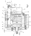
- the tensioning device 10 is e.g. B. in a conventional manner on one machine shown, e.g. B. processing machine attached.
- the clamping device 10 has a generally designated 12 Basic body, essentially any Can have shape and in the embodiment shown as round body is formed.
- the base body 12 is Carrier at least one contact surface 13, which later is described in more detail and which is the contact surface for the forms at least one object 11 to be exciting. part the tensioning device 10 is also at least one carrier 14 with an interchangeable clamping finger 15.
- the clamping finger 15 is on the facing the contact surface 13 Side with at least one clamping surface 16 for the to exciting object 11 provided.
- the to tension the Object 11 applied clamping force is between the Contact surface 13 and the clamping surface 16 effective, the Clamping direction in the illustration in Fig. 1 essentially runs horizontally.
- the at least one carrier 14 with clamping finger 15 is also present an actuator 17 for applying the clamping force in the direction of tension and in the opposite direction.
- an actuator 17 for applying the clamping force in the direction of tension and in the opposite direction.
- the actuation of the Actuator 17 in the direction of arrow c causes the actual clamping of the object 11 between the Clamping surface 16 and the contact surface 13.
- An opposite Movement of the actuator 17 in the direction of arrow d has opening the voltage.
- the at least one carrier 14 is also relative to the Actuator 17 in a direction approximately transverse to the clamping direction, in the illustration in Fig. 1 upwards or downwards below, movable. Furthermore, the carrier 14 is in a bearing block 18 movable relative to this, which in turn in a slot 19 in the base body 12 in the direction is held displaceably transversely to the clamping direction.
- the at least one carrier 14 is in the embodiment shown approximately parallel to the clamping direction, d. H. in 1 approximately in the horizontal direction, in the bearing block 18th displaceable and also in relation to the bearing block 18 kept rotatable.
- the bearing block 18 contains a longitudinal bore 20, in which the carrier 14 in the form of a rod horizontally displaceable.
- the bearing block 18 has a locking projection 21, for. B. in the form of a Bolt with projection, which in an outer groove 22 of the Carrier 14 engages positively.
- the outer groove 22 has an approximately parallel section extending to the longitudinal axis of the carrier 14, in which the locking projection 21 engages, whereby the non-rotatable Bracket is reached.
- the Carrier 14 in addition to the bearing block 18 Longitudinally displaceable or instead of this pivotable about the Axis of the carrier 14 held.
- the outer groove 22 can, for. B. an oblique or arcuate and / or approximately parallel to have its longitudinal axis extending section.
- the oblique or arcuate section causes at the longitudinal displacement of the carrier 14 together with the locking projection 21 a pivoting and / or longitudinal displacement of the Carrier 14 relative to the block 18, so what the axial movement for clamping or releasing an additional Swiveling movement is superimposed.
- the actuating element 17 has approximately one for each carrier 14 transverse to the clamping direction, i.e. in Fig. 1 vertical, extending Slot 23 on that of an end portion 24 of the carrier 14 is interspersed with play, the end portion 24 of the Carrier 14 preferably with respect to the actuator 17 is supported oscillating in the horizontal direction.
- the End part 24 is located on the right in FIG. 1 Surface on a surface there, which is on both sides of the Slot 23 runs on the actuating element 17.
- the end part 24 On on the opposite side, the end part 24 has one Head 25 on a spherical segment-shaped support 26 axially on the facing side of the actuating element 17 is present.
- the tensioning device 10 has one on the at least one Bearing block 18 operating transverse adjustment device 27 a sliding member 28 assigned to the bearing block 18 having.
- the sliding member 28 is in relation to the base body 12 approximately parallel to the clamping direction, that is to say in FIG. 1 roughly horizontal.
- the bearing block 18 is on the sliding link 28 along an oblique to the clamping direction, in Fig. 1st diagonally from top to bottom and from left to right, extending guide surface 29 out.
- This weird Guide surface 29 is designed according to the wedge hook principle and here z. B. designed as a dovetail guide.
- A is on the base body 12 to form the contact surface 13
- Fixed stop 30 interchangeably attached, especially screwed.
- This fixed stop 30 is the respective to exciting object 11 assigned and adapted to this. This adjustment is both in terms of shape as well the dimensions.
- the fixed stop 30 is approximately pot-shaped and arranged according to a lying U, its Ring face, which points to the right in Fig. 1, the Contact surface 13 forms.
- Another, not shown Embodiment with z. B. a differently shaped and / or dimensioned object 11 is the fixed stop 30 in Adaptation designed differently. It serves as a condition for the object 11.
- the fixed stop 30 has a section 31 with one facing the at least one bearing block 18 Stop surface 32 on.
- the stop surface 32 and the associated surface 33 of the at least one Bearing blocks 18 run approximately parallel to the clamping direction, their stop interaction transverse to the clamping direction happens.
- the actuating element 17 is relative to the sliding member 28 and can be operated in translation independently of the latter, especially slidable.
- the actuator 17 on the one hand and the sliding member 28 on the other hand a separate drive for each actuation, in particular a pressure medium operated cylinder, assigned to the is not shown further.
- the sliding member 28 is with a rod 34 connected, at the end 35 a protruding described drive can attack.
- the rod 34 penetrates the actuator 17, which in turn by means of a sleeve 36 on the rod 34 relative to this is displaceable, on the sleeve 36 of the actuating element 17 assigned drive can attack.
- the actuator 17 can with respect to its sleeve 36 be kept swinging.
- the tensioning device 10 can be a longitudinal structure, for example according to Art be formed of a flat bed, with each other Flat surfaces in contact with each other are trained.
- the clamping device 10 essentially as a rotationally symmetrical structure designed, but this is not mandatory.
- Actuating element 17 as a ring part with at least one a protruding finger containing radial slot 23 educated.
- the sliding member 28 consists of a disc.
- the base body 12 has several, for. B. three, in the circumferential direction at preferably equal angular distances from one another arranged blocks 18 with one each Carrier 14 with clamping finger 15 so that in a round object 11 to be tensioned, the tensioning force at several, e.g. B. three, in the circumferential direction in preferably the same Angular distances from each other is effective.
Landscapes
- Engineering & Computer Science (AREA)
- Mechanical Engineering (AREA)
- Jigs For Machine Tools (AREA)
- Electrical Discharge Machining, Electrochemical Machining, And Combined Machining (AREA)
Abstract
Description
- Fig. 1
- einen schematischen Schnitt einer Spanneinrichtung für Gegenstände,
- Fig. 2
- eine Seitenansicht der Spanneinrichtung in Fig. 1.
Claims (20)
- Spanneinrichtung für Gegenstände, z.B. für zu bearbeitende Werkstücke, mit einem Grundkörper (12) mit zumindest einer Anlagefläche (13) für den mindestens einen zu spannenden Gegenstand (11) und mit mindestens einem an einem bewegbaren Träger (14) befindlichen Spannfinger (15) mit zumindest einer Spannfläche (16) für den mindestens einen zu spannenden Gegenstand (11), wobei zwischen der Anlagefläche (13) und der Spannfläche (16) eine Spannkraft zum Spannen des mindestens einen Gegenstandes (11) auf bringbar ist,
dadurch gekennzeichnet,
daß der mindestens eine Träger (14) mit Spannfinger (15) mit einem Betätigungselement (17) zum Aufbringen der Spannkraft in Spannrichtung und gegensinnig dazu in Verbindung steht sowie in Richtung etwa quer zur Spannrichtung relativ zum Betätigungselement (17) beweglich ist und daß der mindestens eine Träger (14) mit Spannfinger (15) ferner in einem Lagerklotz (18) relativ zu diesem beweglich gehalten ist, der seinerseits im Grundkörper (12) etwa quer zur Spannrichtung verschieblich ist. - Spanneinrichtung nach Anspruch 1,
dadurch gekennzeichnet,
daß der mindestens eine Träger (14) im Lagerklotz (18) etwa parallel zur Spannrichtung verschiebbar gehalten ist. - Spanneinrichtung nach Anspruch 1 oder 2,
dadurch gekennzeichnet,
daß der mindestens eine Träger (14) in bezug auf den Lagerklotz (18) undrehbar gehalten ist. - Spanneinrichtung nach einem der Ansprüche 1 bis 3,
dadurch gekennzeichnet,
daß der mindestens eine Träger (14) in bezug auf den Lagerklotz (18) um seine Längsachse schwenkbar und/oder längsverschiebbar gehalten ist. - Spanneinrichtung nach einem der Ansprüche 1 bis 4,
dadurch gekennzeichnet,
daß der Lagerklotz (18) eine Längsbohrung (20) enthält, in der der Träger (14) in der Ausbildung als Stange beweglich aufgenommen ist. - Spanneinrichtung nach einem der Ansprüche 1 bis 5,
dadurch gekennzeichnet,
daß der Lagerklotz (18) einen Sperrvorsprung (21) aufweist, der in eine Außennut (22) des Trägers (14) formschlüssig eingreift. - Spanneinrichtung nach Anspruch 6,
dadurch gekennzeichnet,
daß die Außennut (22) des Trägers (14) einen schräg bzw. bogenförmig und/oder etwa parallel zu dessen Längsachse verlaufenden Abschnitt aufweist, mittels dessen im Zusammenwirken mit dem eingreifenden Sperrvorsprung (21) bei der Längsverschiebung des Trägers (14) dessen Schwenkung und/oder Längsverschiebung relativ zum Lagerklotz (18) steuerbar ist. - Spanneinrichtung nach einem der Ansprüche 1 bis 7,
dadurch gekennzeichnet,
daß das Betätigungselement (17) je Träger (14) einen quer zur Spannrichtung verlaufenden Schlitz (23) aufweist, der von einem Endteil (24) des Trägers (14) mit Spiel durchsetzt ist, wobei der Endteil (24) des Trägers (14) in bezug auf das Betätigungselement (17) vorzugsweise pendelnd abgestützt ist. - Spanneinrichtung nach einem der Ansprüche 1 bis 8,
gekennzeichnet durch
eine auf den mindestens einen Lagerklotz (18) arbeitende Querverstelleinrichtung (27). - Spanneinrichtung nach Anspruch 9,
dadurch gekennzeichnet,
daß die Querverstelleinrichtung (27) ein dem Lagerklotz (18) zugeordnetes Schiebeglied (28) aufweist, das in bezug auf den Grundkörper (12) etwa parallel zur Spannrichtung geführt ist, und daß der Lagerklotz (18) am Schiebeglied (28) längs einer schräg zur Spannrichtung verlaufenden Führungsfläche (29)geführt ist. - Spanneinrichtung nach einem der Ansprüche 1 bis 10,
dadurch gekennzeichnet,
daß am Grundkörper (12) zur Bildung der Anlagefläche (13) ein Festanschlag (30) auswechselbar befestigt ist, der dem jeweiligen zu spannenden Gegenstand (11) zugeordnet und an diesen angepaßt ist. - Spanneinrichtung nach Anspruch 11,
dadurch gekennzeichnet,
daß der Festanschlag (30) einen Abschnitt (31) mit einer dem mindestens einen Lagerklotz (18) zugewandten Anschlagfläche (32) aufweist und daß der mindestens eine Lagerklotz (18) eine zugewandte Fläche (33) aufweist, mit der der Lagerklotz (18) bei seiner Einstellung mittels der Querverstelleinrichtung (27) an der Anschlagfläche (32) unter Erreichen der dem jeweiligen zu spannenden Gegenstand (11) zugeordneten Sollausgangsposition zum Spannen anschlägt. - Spanneinrichtung nach Anspruch 12,
dadurch gekennzeichnet,
daß die Anschlagfläche (32) und die zugeordnete Fläche (33) des mindestens einen Lagerklotzes (18) etwa parallel zur Spannrichtung verlaufen und deren Anschlagzusammenwirkung quer zur Spannrichtung geschieht. - Spanneinrichtung nach einem der Ansprüche 10 bis 13,
dadurch gekennzeichnet,
daß die schräg verlaufende Führungsfläche (29) nach dem Keilhakenprinzip gestaltet ist, z.B. als Schwalbenschwanzführung ausgebildet ist. - Spanneinrichtung nach einem der Ansprüche 1 bis 14,
dadurch gekennzeichnet,
daß das Betätigungselement (17) relativ zum Schiebeglied (28) und unabhängig von diesem translatorisch betätigbar, insbesondere verschiebbar, ist. - Spanneinrichtung nach einem der Ansprüche 1 bis 15,
dadurch gekennzeichnet,
daß dem Betätigungselement (17) einerseits und dem Schiebeglied (28) andererseits zur jeweiligen Betätigung jeweils ein eigener Antrieb, insbesondere ein druckmittelbetriebener Arbeitszylinder, zugeordnet ist. - Spanneinrichtung nach einem der Ansprüche 1 bis 16,
dadurch gekennzeichnet,
daß das Betätigungselement (17) als Ringteil mit mindestens einem einen Schlitz (23) enthaltenden abstehenden Finger ausgebildet ist. - Spanneinrichtung nach einem der Ansprüche 1 bis 17,
dadurch gekennzeichnet,
daß das Schiebeglied (28) aus einer Scheibe besteht. - Spanneinrichtung nach einem der Ansprüche 1 bis 18,
dadurch gekennzeichnet,
daß der Grundkörper (12) mehrere, z.B. drei, in Umfangsrichtung in vorzugsweise gleichen Umfangswinkelabständen voneinander angeordnete Lagerklötze (18) mit jeweils einem Träger (14) mit Spannfinger (15) aufweist. - Spanneinrichtung nach einem der Ansprüche 11 bis 19,
dadurch gekennzeichnet,
daß der Festanschlag (30) etwa topfförmig gestaltet und entsprechend einem liegenden U angeordnet ist, wobei dessen Ringstirnfläche die Anlagefläche (13) bildet.
Applications Claiming Priority (2)
| Application Number | Priority Date | Filing Date | Title |
|---|---|---|---|
| DE19921528 | 1999-05-11 | ||
| DE19921528A DE19921528A1 (de) | 1999-05-11 | 1999-05-11 | Spanneinrichtung für Gegenstände, z. B. für zu bearbeitende Werkstücke |
Publications (2)
| Publication Number | Publication Date |
|---|---|
| EP1052046A2 true EP1052046A2 (de) | 2000-11-15 |
| EP1052046A3 EP1052046A3 (de) | 2002-08-07 |
Family
ID=7907601
Family Applications (1)
| Application Number | Title | Priority Date | Filing Date |
|---|---|---|---|
| EP00106774A Withdrawn EP1052046A3 (de) | 1999-05-11 | 2000-03-30 | Spanneinrichtung für Gegenstände, z.B. für zu bearbeitende Werkstücke |
Country Status (3)
| Country | Link |
|---|---|
| US (1) | US6367816B1 (de) |
| EP (1) | EP1052046A3 (de) |
| DE (2) | DE19921528A1 (de) |
Cited By (1)
| Publication number | Priority date | Publication date | Assignee | Title |
|---|---|---|---|---|
| WO2019185239A1 (de) * | 2018-03-29 | 2019-10-03 | Sterman Technische Systeme Gmbh | Spannvorrichtung, werkzeugmaschine und verfahren zum intelligenten spannen eines werkstückes |
Families Citing this family (12)
| Publication number | Priority date | Publication date | Assignee | Title |
|---|---|---|---|---|
| DE10207567A1 (de) * | 2002-02-22 | 2003-09-04 | Roehm Gmbh | Kugelbolzenfutter |
| US6910693B2 (en) * | 2003-01-17 | 2005-06-28 | Mp Tool & Engineering, Co. | Draw down chuck |
| EP1862241B1 (de) * | 2006-06-03 | 2011-10-05 | SMW-AUTOBLOK Spannsysteme GmbH | Kraftspannfutter |
| DE102006043730B3 (de) * | 2006-09-13 | 2008-01-31 | Karlein, Eugen F. | Systempendelvorrichtung für ein Spannfutter zum Spannen von Werkstücken und Spannfutter |
| US8454028B1 (en) * | 2009-03-25 | 2013-06-04 | Honda Motor Co., Ltd. | Fixture for holding a chamfering tool during cutting insert preset operation |
| DE212010000101U1 (de) * | 2009-07-13 | 2012-04-03 | Illinois Tool Works Inc. | Spannfutter mit Backe für Werkstücke mit konstanter Haltekraft |
| CN107639562B (zh) * | 2017-09-20 | 2024-02-06 | 广东拓斯达科技股份有限公司 | 一种用于易碎片状体的治具 |
| CN112510491B (zh) * | 2020-11-06 | 2025-07-04 | 国网河南省电力公司济源供电公司 | Jp柜接地装置 |
| CN113284671B (zh) * | 2021-05-31 | 2025-06-13 | 江苏中利集团股份有限公司 | 自动对中结构 |
| CN114473730B (zh) * | 2022-01-17 | 2023-05-09 | 清华大学 | 用于夹持带沟槽零部件的夹具组件及夹持方法 |
| CN117067135A (zh) * | 2023-09-19 | 2023-11-17 | 丹东日牵物流装备有限公司 | 一种双拉锁旋转回弹压板装置 |
| CN117644410B (zh) * | 2024-01-29 | 2024-04-26 | 象山申达轿车配件有限公司 | 一种分油盘定位夹持装置 |
Family Cites Families (8)
| Publication number | Priority date | Publication date | Assignee | Title |
|---|---|---|---|---|
| US2733072A (en) * | 1956-01-31 | Finger chuck | ||
| US1412170A (en) * | 1922-04-11 | Walteb l | ||
| US1881905A (en) * | 1931-06-05 | 1932-10-11 | Heald Machine Co | Chuck |
| US2893744A (en) * | 1957-11-04 | 1959-07-07 | Nat Broach & Mach | Centering chuck |
| DE1239169B (de) * | 1959-12-02 | 1967-04-20 | Berliner Werkzeugmasch | Spannfutter zum zentrischen, verformungsfreien und automatischen Spannen duennwandiger Werkstuecke |
| FR1263566A (fr) * | 1960-07-18 | 1961-06-09 | Deutschland A G Maschf | Dispositif d'entraînement hydraulique pour tours pour trains de roues |
| US3420538A (en) * | 1966-01-21 | 1969-01-07 | Erickson Tool Co | Swivel finger chuck |
| IT1208041B (it) * | 1987-05-15 | 1989-06-01 | Tva Holding | Tavola portapezzo per macchine utensili con dispositivo di centraggio e bloccaggio di un pezzo da lavorare. |
-
1999
- 1999-05-11 DE DE19921528A patent/DE19921528A1/de not_active Withdrawn
- 1999-06-10 DE DE29910130U patent/DE29910130U1/de not_active Expired - Lifetime
-
2000
- 2000-03-30 EP EP00106774A patent/EP1052046A3/de not_active Withdrawn
- 2000-05-03 US US09/563,357 patent/US6367816B1/en not_active Expired - Fee Related
Cited By (1)
| Publication number | Priority date | Publication date | Assignee | Title |
|---|---|---|---|---|
| WO2019185239A1 (de) * | 2018-03-29 | 2019-10-03 | Sterman Technische Systeme Gmbh | Spannvorrichtung, werkzeugmaschine und verfahren zum intelligenten spannen eines werkstückes |
Also Published As
| Publication number | Publication date |
|---|---|
| DE29910130U1 (de) | 1999-08-12 |
| EP1052046A3 (de) | 2002-08-07 |
| DE19921528A1 (de) | 2000-11-16 |
| US6367816B1 (en) | 2002-04-09 |
Similar Documents
| Publication | Publication Date | Title |
|---|---|---|
| EP1272409B1 (de) | Handhabungsgerät zum umpositionieren von teilen | |
| DE10118664B4 (de) | Spanneinrichtung für zu bearbeitende Werkstücke mit Unwuchtausgleich | |
| EP1052046A2 (de) | Spanneinrichtung für Gegenstände, z.B. für zu bearbeitende Werkstücke | |
| DE2915327C2 (de) | Arbeitsmaschine mit Fingerschutzeinrichtung für das bewegbare Oberwerkzeug | |
| DE3234675A1 (de) | Verriegelungsvorrichtung fuer werkzeuge in werkzeugmagazinen | |
| DE3007261A1 (de) | Vorrichtung zum halten von werkstuecken bei honbearbeitung | |
| DE102018119980A1 (de) | Spann- oder Greifeinrichtung | |
| DE3329942C1 (de) | Spannvorrichtung für insbes. spanabhebend zu bearbeitende Werkstücke | |
| DE2206305A1 (de) | Formschliesseinrichtung fuer thermoplastische massen verarbeitende maschinen | |
| DE2134487C3 (de) | Rundschalttisch mit einem Schaltteller | |
| DE3223761C2 (de) | Abziehwerkzeug für Schrämmeißel | |
| DE2216943A1 (de) | Rückstellmechanismus mit veränderlichem Hub, insbesondere für eine Werkzeugmaschine | |
| DE10201384B4 (de) | Reibkupplungseinrichtung | |
| EP0436883A1 (de) | Spannvorrichtung | |
| DE7537486U (de) | Revolverstanzpresse | |
| DE3413478C2 (de) | Vorrichtung zum Einsetzen eines offenen, mit Montagelöchern in den Endabschnitten versehenen Federrings in eine Umfangsnut einer Bohrung oder Welle | |
| DE1552612A1 (de) | Schneidemaschine fuer Stabmaterial | |
| DE2741918A1 (de) | Werkzeugmaschine mit einrichtungen zum wahlweisen anbringen eines keilnuten- ziehmessers und eines raeumwerkzeuges | |
| EP1068054B1 (de) | Einrichtung zum längsteilen von materialbahnen mit positioniereinrichtung für die messerhalter | |
| DE4101317A1 (de) | Lochgreifer | |
| DE2556166C3 (de) | Honwerkzeug | |
| DE102007026980A1 (de) | Niethaltevorrichtung | |
| DE1552289C (de) | Kraftbetatigte Spannvorrichtung , ins besondere Backenfutter | |
| DE69109843T2 (de) | Endbearbeitungsvorrichtung für Werkstücke. | |
| DE2063343C3 (de) | Schneidwerkzeug, insbesondere Feindrehwerkzeug |
Legal Events
| Date | Code | Title | Description |
|---|---|---|---|
| PUAI | Public reference made under article 153(3) epc to a published international application that has entered the european phase |
Free format text: ORIGINAL CODE: 0009012 |
|
| AK | Designated contracting states |
Kind code of ref document: A2 Designated state(s): AT BE CH CY DE DK ES FI FR GB GR IE IT LI LU MC NL PT SE |
|
| AX | Request for extension of the european patent |
Free format text: AL;LT;LV;MK;RO;SI |
|
| PUAL | Search report despatched |
Free format text: ORIGINAL CODE: 0009013 |
|
| AK | Designated contracting states |
Kind code of ref document: A3 Designated state(s): AT BE CH CY DE DK ES FI FR GB GR IE IT LI LU MC NL PT SE |
|
| AX | Request for extension of the european patent |
Free format text: AL;LT;LV;MK;RO;SI |
|
| AKX | Designation fees paid | ||
| REG | Reference to a national code |
Ref country code: DE Ref legal event code: 8566 |
|
| STAA | Information on the status of an ep patent application or granted ep patent |
Free format text: STATUS: THE APPLICATION IS DEEMED TO BE WITHDRAWN |
|
| 18D | Application deemed to be withdrawn |
Effective date: 20030208 |