EP1052003A2 - Tête de fermeture pour un ballon gonflable au gaz - Google Patents
Tête de fermeture pour un ballon gonflable au gaz Download PDFInfo
- Publication number
- EP1052003A2 EP1052003A2 EP00109818A EP00109818A EP1052003A2 EP 1052003 A2 EP1052003 A2 EP 1052003A2 EP 00109818 A EP00109818 A EP 00109818A EP 00109818 A EP00109818 A EP 00109818A EP 1052003 A2 EP1052003 A2 EP 1052003A2
- Authority
- EP
- European Patent Office
- Prior art keywords
- wall
- closure head
- head
- balloon
- closure
- Prior art date
- Legal status (The legal status is an assumption and is not a legal conclusion. Google has not performed a legal analysis and makes no representation as to the accuracy of the status listed.)
- Withdrawn
Links
Images


Classifications
-
- A—HUMAN NECESSITIES
- A63—SPORTS; GAMES; AMUSEMENTS
- A63H—TOYS, e.g. TOPS, DOLLS, HOOPS OR BUILDING BLOCKS
- A63H27/00—Toy aircraft; Other flying toys
- A63H27/10—Balloons
-
- A—HUMAN NECESSITIES
- A63—SPORTS; GAMES; AMUSEMENTS
- A63H—TOYS, e.g. TOPS, DOLLS, HOOPS OR BUILDING BLOCKS
- A63H27/00—Toy aircraft; Other flying toys
- A63H27/10—Balloons
- A63H2027/1041—Holding or sealing means, e.g. handling rods, clamps or plugs
-
- A—HUMAN NECESSITIES
- A63—SPORTS; GAMES; AMUSEMENTS
- A63H—TOYS, e.g. TOPS, DOLLS, HOOPS OR BUILDING BLOCKS
- A63H27/00—Toy aircraft; Other flying toys
- A63H27/10—Balloons
- A63H2027/1058—Balloons associated with light or sound
-
- A—HUMAN NECESSITIES
- A63—SPORTS; GAMES; AMUSEMENTS
- A63H—TOYS, e.g. TOPS, DOLLS, HOOPS OR BUILDING BLOCKS
- A63H27/00—Toy aircraft; Other flying toys
- A63H27/10—Balloons
- A63H2027/1083—Valves or nozzles
-
- A—HUMAN NECESSITIES
- A63—SPORTS; GAMES; AMUSEMENTS
- A63H—TOYS, e.g. TOPS, DOLLS, HOOPS OR BUILDING BLOCKS
- A63H27/00—Toy aircraft; Other flying toys
- A63H27/10—Balloons
- A63H2027/1091—Balloons with object inserted within; Means or methods for insertion of objects
Definitions
- the invention relates to a closure head for a gas inflatable balloon according to the preamble of claim 1.
- Such a closure head is known from EP 0 241 452 B1 known.
- the one shown in Fig. 8 of EP 0 241 452 B1 Breech head has a gas supply channel that between the Housing 7 and the reflector 15 is formed.
- the exit of the gas supply channel is through through openings 19 in the Reflector 5 formed. Since the passage openings in the Reflector are formed, they can not be any be enlarged to a sufficient flow cross-section for inflating the balloon without providing to impair the reflectivity of the reflector. They are also used for the production of through openings additional operations are necessary.
- the invention is therefore based on the object, the closure head to further develop according to the preamble of claim 1, that any flow cross section for the Gas supply channel can be made available without the Impair the function of the other components.
- Another object of the present invention is to provide a Locking head according to the preamble of claim 1 such to further develop that it is simple and inexpensive to manufacture can be.
- the closure head has a tubular Outer part, on the outer surface of which a balloon is drawn can be a tubular inner part.
- the inner part and the outer part of the gas supply channel defines that the exit of the gas supply channel for the supply of gas to inflate one drawn on the breech head Balloons arranged between the inner part and the outer part is. Since the holder for the light source inside the Is arranged internally, the flow cross section of the Exit simply enlarged by enlarging the outer part without the function and design of the bracket influence.
- the inner part and / or the outer part are preferably cylindrical trained to be a simple and inexpensive Ensure manufacture of the closure head.
- the outer part can also be conically tapered, so that the balloon can be pulled up more easily on the closure head can be.
- Conical outer part so that the largest diameter of the outer part in the area of the outlet of the gas supply channel is to prevent the balloon from slipping off the closure head reliably prevent.
- a groove can advantageously also be provided in the outer part be provided as a holder for a portion of the Balloon neck serves.
- the inner part and the outer part are preferably concentric arranged to each other for easy and inexpensive manufacture to ensure.
- This arrangement has the other Advantage that the exit has a circular cross section an associated constant flow cross-section having.
- the air inlet for the gas supply duct is advantageous a tubular part, the axis of which is parallel to the axis of the tubular outer part runs. Because these two parts run parallel to each other, manufacturing is easy and inexpensive.
- the closure head has an outer wall, on the surface of which a balloon can be put up, an inner wall that defines a passage into which one Light source can be inserted.
- the passage is opposite the interior of the balloon with a cap that preferably has a dome made of transparent material, locked. Since the gas supply channel between the inner wall and the outer wall is defined, the flow cross section of the Exit simply enlarged by enlarging breakthroughs without the function and design of the light source influence.
- Closure head can be used.
- the closure head has two parts on, the first part the outer wall and the inner wall forms, and the second part of a substantially transparent Material is formed that from the inner wall defined passage towards the inside of the balloon seals.
- the light source can preferably be a cap trained second part can be arranged by in the is introduced from the inner wall 1012 defined passage.
- the second part is preferably glued to the inner wall, to create an airtight connection.
- closure head according to claim 16 with the in the independent Features specified claims represents the preferred Embodiment of the invention.
- This closure head can with a light head can be combined, preferably on a Extruder tube is attached, with an adapter to one commercially available handle for batteries, for example one Handle of a flashlight, can be connected.
- Fig. 1 shows a cross section of the preferred embodiment the invention.
- On the outer surface 111 of the cylindrical A balloon 100 is drawn up on the outer part 11.
- the cylindrical outer part 11 closes the cylindrical one Inner part 12 a.
- the gas supply channel 14 is defined. Gas, i.e. Air or a commercially available gas, e.g. Helium or hydrogen etc., can via the gas inlet 13 in the gas supply channel 14th be initiated.
- the check valve 17 prevents that gas under pressure in the balloon 100 via the gas inlet 13 flows into the environment.
- the outer part 11 is with the Inner part 12 connected via the base plate 16.
- In the Base plate 16 is in the area of gas inlet 13 Opening for gas supply provided. It's at the opening Check valve 17 is provided.
- the gas supply channel 14 has an outlet 15 with an annular cross section.
- the holder 20 is for a lamp 22 shown schematically arranged.
- the bracket has a reflector 21, in the center of which is a schematic Version 23 shown for a lamp 22 is arranged.
- the reflector 21 is in the embodiment of FIG. 1 connected gas-tight to the inner part 12.
- the lamp is supplied with power via the two cables 24 and 25 connected to a battery 26.
- the power supply can also be connected directly from Batteries are done.
- the power supply can also like with conventional fairy lights.
- Fig. 2 shows a cross section along the line II-II of the in Fig. 1 shown closure head.
- the closure head of Fig. 2 is shown without the balloon inflated.
- the direction of view corresponds to a view of the closure head shown in FIG. 1 from above.
- Inside the outer part 11 is the inner part 12 arranged.
- Between the outer part 11 and the inner part 12 the gas supply channel 14 is defined.
- the outlet 15 of the gas supply channel 14 has an annular cross section.
- the reflector 21 is arranged inside the inner part 12.
- the lamp 22 is arranged in the middle of the reflector 21.
- the Gas inlet 13 is shown schematically on the right side. For the sake of clarity, the check valve 17 has not been shown.
- the Gas inlet also through a simple opening in the bottom part 16 be formed with the between the inner part 12 and the Outer part 11 formed gas supply channel 14 in connection stands and is closed by the check valve 17.
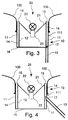
- FIG. 3 shows a cross section corresponding to FIG. 1 another embodiment.
- the power supply i.e. for example the cables 24 and 25 and the battery 26, omitted for clarity.
- the 3 shown in Fig. differs from the embodiment shown in Fig. 1 in that the bottom part 16 is annular.
- the bottom part 16 extends between the lower end of the outer part 11 and the lower end of the inner part 12.
- the inner part 12 enclosed area is open.
- the version and the back of the reflector 21 freely accessible from below.
- Internal thread can be provided by means of which the closure head a bracket can be screwed. Since the version 23 for the lamp 22 is freely accessible from below, any one Power supply can be easily connected to the socket.
- a handle on the locking head be arranged in which batteries are accommodated.
- batteries For one easy battery replacement could be at the bottom of the Handles a bayonet catch with a circuit board be provided, which are electrically connected to the socket 23 is when the bayonet lock is closed to the To provide power supply.
- FIG. 4 shows a cross section corresponding to FIG. 1 another embodiment of the closure head according to the invention. For the sake of clarity, it is the same as that shown in FIG. 3 Locking head omitted the power supply for the socket 23.
- the embodiment of Fig. 4 differs of the embodiment shown in Figures 1 and 2 in that the gas inlet 13 is not at the bottom part 16, but is arranged in the outer part 13.
- the gas inlet 13 is designed as a tubular part. One end of the tubular Part is connected to the gas supply channel 14.
- a check valve 17 prevents that in the balloon 100 pressurized gas through the gas inlet 13 into the environment emanates.
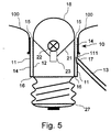
- FIG. 5 shows a cross section corresponding to FIG. 1 another embodiment of the closure head according to the invention.
- the one shown in Fig. 5 Closure head has a lamp screw base 27.
- the size of the lamp screw base 27 is the one for example lamp screw holders commonly used for inside or outside surfaces adapted and can be chosen freely.
- the lamp screw base can be used as an E27 or E14 base be trained.
- the breech head with a wound on it Ballon 100 can be placed in an external lamp holder be screwed in, which are connected to an external power source is.
- the closure head shown in FIG. 5 also differs from the closure head shown in Figures 1 and 2 in that a transparent above the lamp Cap 18 is provided.
- the transparent cap 18 is connected flush with the inner part 12. Compared to that in 7 of the closure head shown in EP 0 241 452 B1 Advantage of the invention particularly clear, because the closure head according to the invention due to the double cylinder structure from outer part 11 and inner part 12 through openings Neither in the reflector 21 nor in the cap 18 are necessary.
- this can Gas inlet also closed only by the check valve 17 Opening may be provided in the outer part 11.
- a cap corresponding to the cap shown in FIG. 5 can also in those shown in FIGS. 1 to 4 or in FIGS closure heads provided in the appended claims become.
- Fig. 6 shows the preferred embodiment of an inventive Locking head 1000, which is associated with a light source 1022 and a tube 1040 is shown cut over an adapter 1030 with a commercially available handle 1026 connected to a flashlight.
- a commercially available handle 1026 connected to a flashlight.
- the handle 1026 are in known manner batteries for the power supply of the Provide light source 1022.
- the locking head 1000 is shown in more detail in FIGS. 7 and 8 shown and is in connection with this figure described.
- the light source 1022 is, for example, a commercially available one Pear, which is provided in a version 1023.
- the version 1023 is arranged in a tube 1040.
- the pipe is 1040 preferably extruded and can also be made from one Can consist of material that is somewhat flexible.
- the extruder tube is used for assembly up to the stop 1019 in the locking head 1000 inserted and preferably fits snugly or non-slip in it.
- a firm connection for example, gluing
- the Tube 1040 leads cables 1024 and 1025 to the commercially available Handle 1026. Instead of a commercially available handle any other power source, of course be used.
- the tube 1040 is connected to a commercially available handle adapted adapter connected to the handle 1026.
- the Adapter 1030 fits the pipe with a precise fit. With its thread In 1031 it is screwed into the handle.
- At the bottom of the Adapters are suitable contacts for connecting to the in the handle to insert batteries provided.
- a switch can also be provided on the adapter.
- FIG. 7 shows a section of the first part 1001 of the one in FIG. 6 shown closure head 1000. It preferably has one cylindrical outer wall 1011, on the surface 1111 a balloon according to FIGS. 1 to 5 are raised can.
- the outer wall 1011 preferably faces those in FIG. 7 a widening at the top to prevent the To prevent balloons from surface 1111.
- the first part 1001 also has an inner wall 1012 that defines a passage 1112 defined by the locking head 1000.
- the inner wall 1012 connects to the outer wall 1011.
- the Inner wall 1012 arranged concentrically with the outer wall 1011.
- the inner wall preferably has a cylindrical shape.
- the inner wall 1012 can any shape give that is adapted to the light source to be introduced.
- the outer wall 1011 can also have any shape as long as it has a surface on which the Balloon can be applied airtight.
- a stop 1019 is provided on the inner wall 1012 through a passage formed by the inner wall 1012 protruding projection is formed. With the stop 1019 is a defined positioning of the in the passage guaranteed light source to be introduced.
- the second part 1002 has a cap 1018 to which a circular disk-shaped wall 1018A connects.
- the cap 1018 preferably has a transparent dome.
- steps 1018B and 1018C provided an exact positioning of the second Guarantee part 1002 on in the first part 1001, because that second part 1002 with the thicker part of wall 1018A in the Opening between the outer wall 1011 and the inner wall 1012 engages while the thin area of wall 1018A is on the Outer wall 1011 and the inner wall 1012 rests.
- steps 1018B and 1018C provided an exact positioning of the second Guarantee part 1002 on in the first part 1001, because that second part 1002 with the thicker part of wall 1018A in the Opening between the outer wall 1011 and the inner wall 1012 engages while the thin area of wall 1018A is on the Outer wall 1011 and the inner wall 1012 rests.
- the wall Breakthroughs are provided to prevent air leakage into the 1018A Ensure inside of the balloon.
- the first part 1001 is preferably with the second part 1002 hermetically connected.
- this can be done by a Glue between the cap 1018 and the inner wall 1012 happen.
- the light source 1022 could also be used by inserting into the passage 1112 of the interior from the Locking head 1000 inflated balloons against the environment seal.
- this has the disadvantage that when removing the Light source from the shutter head the air from inside the Balloons escape. Therefore, it is preferred that an airtight Connection between the second part 1002 and the first part 1001 at least between the inner wall 1012 and the cap 1018 is trained.
- a better connection could also be made the outer wall 1011 with the edge of the wall 1018A in the area of Level 1018B glued.
- the closure head 1000 has one in the outer wall 1011 Gas inlet 1013 on. 6, the locking head is 1000 in Connection shown with other parts.
- the outer wall 1011 in the area of the gas inlet 1013 closable filler neck injected or with the Outer wall 1011 connected airtight (for example by a Bonding).
- the filler neck is closed in the illustrated embodiment with a commercially available elastic stopper.
- the invention also relates to a closure head according to the Claims 16 to 19 with one or more features is further developed according to claims 1 to 15. As well the invention also relates to a closure head according to one of the Claims 1 to 15, according to one or more features of claims 16 to 19 is developed.
- the described locking heads are for example commercially available, translucent gas balloons, such as toy air balloons, Balloons for advertising and decorative purposes etc., usable.
- the closure head is preferably used as an injection molded part manufactured.
Applications Claiming Priority (4)
| Application Number | Priority Date | Filing Date | Title |
|---|---|---|---|
| DE1999121789 DE19921789A1 (de) | 1999-05-11 | 1999-05-11 | Verschlusskopf für einen mit Gas aufblasbaren Ballon |
| DE19921789 | 1999-05-11 | ||
| DE10009553 | 2000-02-29 | ||
| DE2000109553 DE10009553A1 (de) | 2000-02-29 | 2000-02-29 | Verschlußkopf für einen mit Gas aufblasbaren Ballon |
Publications (2)
| Publication Number | Publication Date |
|---|---|
| EP1052003A2 true EP1052003A2 (fr) | 2000-11-15 |
| EP1052003A3 EP1052003A3 (fr) | 2003-04-23 |
Family
ID=26004579
Family Applications (1)
| Application Number | Title | Priority Date | Filing Date |
|---|---|---|---|
| EP00109818A Withdrawn EP1052003A3 (fr) | 1999-05-11 | 2000-05-09 | Tête de fermeture pour un ballon gonflable au gaz |
Country Status (1)
| Country | Link |
|---|---|
| EP (1) | EP1052003A3 (fr) |
Cited By (1)
| Publication number | Priority date | Publication date | Assignee | Title |
|---|---|---|---|---|
| AT501446A1 (de) * | 2004-09-21 | 2006-09-15 | Andreas Braunboeck | Vorrichtung zur aufnahme eines aufblasbaren ballons |
Citations (1)
| Publication number | Priority date | Publication date | Assignee | Title |
|---|---|---|---|---|
| EP0241452B1 (fr) | 1984-10-29 | 1992-05-13 | HIERAT, Alexander | Dispositif supplementaire pour ballon gonflable |
Family Cites Families (7)
| Publication number | Priority date | Publication date | Assignee | Title |
|---|---|---|---|---|
| US1229794A (en) * | 1916-07-20 | 1917-06-12 | Arthur Salzer | Illuminated toy balloon and lighting effect. |
| US1832408A (en) * | 1930-05-13 | 1931-11-17 | John H Modes | Means for producing novel effects in decoration and the like |
| US3536906A (en) * | 1968-10-28 | 1970-10-27 | Miner Ind Inc | Illuminated balloon device |
| DE2904514A1 (de) * | 1979-02-07 | 1980-08-21 | Anton Szollmann | Ventil fuer kinderballons |
| DE3015962A1 (de) * | 1980-04-25 | 1981-11-05 | Anton 7500 Karlsruhe Szollmann | Vorrichtung zum halten und beleuchten von aufblasbaren luftballons |
| US4542445A (en) * | 1984-01-03 | 1985-09-17 | Louis J. Castaldo | Electric light balloon |
| EP0179949A1 (fr) * | 1984-10-29 | 1986-05-07 | Robert Neumeier | Accessoire complémentaire pour ballon |
-
2000
- 2000-05-09 EP EP00109818A patent/EP1052003A3/fr not_active Withdrawn
Patent Citations (1)
| Publication number | Priority date | Publication date | Assignee | Title |
|---|---|---|---|---|
| EP0241452B1 (fr) | 1984-10-29 | 1992-05-13 | HIERAT, Alexander | Dispositif supplementaire pour ballon gonflable |
Cited By (2)
| Publication number | Priority date | Publication date | Assignee | Title |
|---|---|---|---|---|
| AT501446A1 (de) * | 2004-09-21 | 2006-09-15 | Andreas Braunboeck | Vorrichtung zur aufnahme eines aufblasbaren ballons |
| AT501446B1 (de) * | 2004-09-21 | 2008-03-15 | Andreas Braunboeck | Vorrichtung zum einstecken in einen aufblasbaren ballon |
Also Published As
| Publication number | Publication date |
|---|---|
| EP1052003A3 (fr) | 2003-04-23 |
Similar Documents
| Publication | Publication Date | Title |
|---|---|---|
| EP0241452B1 (fr) | Dispositif supplementaire pour ballon gonflable | |
| WO1986003421A1 (fr) | Accessoire pour ballon gonflable rempli de gaz | |
| DD243971A5 (de) | Verschlusskopf eines gasballons | |
| DE3525672C2 (fr) | ||
| EP2622261A1 (fr) | Ensemble servant à émettre de la lumière | |
| EP1052003A2 (fr) | Tête de fermeture pour un ballon gonflable au gaz | |
| DE10009553A1 (de) | Verschlußkopf für einen mit Gas aufblasbaren Ballon | |
| EP0075839A1 (fr) | Lampe électrique | |
| DE10116957A1 (de) | Fahrzeugleuchte | |
| EP1108182B1 (fr) | Dispositif d'eclairage | |
| EP1253375B1 (fr) | Lampe antidéflagrante | |
| EP0179949A1 (fr) | Accessoire complémentaire pour ballon | |
| DE19921789A1 (de) | Verschlusskopf für einen mit Gas aufblasbaren Ballon | |
| DE1766713B1 (de) | Laryngoskop mit Fiberglaslichtleiter | |
| DE202007005888U1 (de) | Leuchteneinrichtung | |
| DE4411890C2 (de) | Lampenhalterung für eine Leuchte | |
| DE2632462A1 (de) | Leuchtdiode | |
| DE10253887A1 (de) | Beleuchtungsvorrichtung sowie lösbare Verbindung zwischen zwei Leitungen, auch für die Verwendung bei einer Beleuchtungsvorrichtung | |
| DE10212353A1 (de) | Beleuchtungseinrichtung | |
| DE202012102460U1 (de) | Zoom-Taschenlampe | |
| DE10353893B3 (de) | Halterungsvorrichtung für aufblasbare Ballone | |
| DE202015106015U1 (de) | Leuchtdiodenmodul und Leuchte mit mindestens einem Leuchtdiodenmodul | |
| DE202010012951U1 (de) | Lampe | |
| DE60311242T2 (de) | Signalvorrichtung für Sichtortungssystem, z.B. für Rettungsfahrzeug in Schiffahrtkunde und ähnliche Bereiche | |
| DE2649104A1 (de) | Kugelleuchte |
Legal Events
| Date | Code | Title | Description |
|---|---|---|---|
| PUAI | Public reference made under article 153(3) epc to a published international application that has entered the european phase |
Free format text: ORIGINAL CODE: 0009012 |
|
| AK | Designated contracting states |
Kind code of ref document: A2 Designated state(s): AT BE CH CY DE DK ES FI FR GB GR IE IT LI LU MC NL PT SE |
|
| AX | Request for extension of the european patent |
Free format text: AL;LT;LV;MK;RO;SI |
|
| PUAL | Search report despatched |
Free format text: ORIGINAL CODE: 0009013 |
|
| AK | Designated contracting states |
Designated state(s): AT BE CH CY DE DK ES FI FR GB GR IE IT LI LU MC NL PT SE |
|
| AX | Request for extension of the european patent |
Extension state: AL LT LV MK RO SI |
|
| STAA | Information on the status of an ep patent application or granted ep patent |
Free format text: STATUS: THE APPLICATION IS DEEMED TO BE WITHDRAWN |
|
| 18D | Application deemed to be withdrawn |
Effective date: 20021203 |