EP1052003A2 - Closure head for a gas inflatable balloon - Google Patents
Closure head for a gas inflatable balloon Download PDFInfo
- Publication number
- EP1052003A2 EP1052003A2 EP00109818A EP00109818A EP1052003A2 EP 1052003 A2 EP1052003 A2 EP 1052003A2 EP 00109818 A EP00109818 A EP 00109818A EP 00109818 A EP00109818 A EP 00109818A EP 1052003 A2 EP1052003 A2 EP 1052003A2
- Authority
- EP
- European Patent Office
- Prior art keywords
- wall
- closure head
- head
- balloon
- closure
- Prior art date
- Legal status (The legal status is an assumption and is not a legal conclusion. Google has not performed a legal analysis and makes no representation as to the accuracy of the status listed.)
- Withdrawn
Links
Images


Classifications
-
- A—HUMAN NECESSITIES
- A63—SPORTS; GAMES; AMUSEMENTS
- A63H—TOYS, e.g. TOPS, DOLLS, HOOPS OR BUILDING BLOCKS
- A63H27/00—Toy aircraft; Other flying toys
- A63H27/10—Balloons
-
- A—HUMAN NECESSITIES
- A63—SPORTS; GAMES; AMUSEMENTS
- A63H—TOYS, e.g. TOPS, DOLLS, HOOPS OR BUILDING BLOCKS
- A63H27/00—Toy aircraft; Other flying toys
- A63H27/10—Balloons
- A63H2027/1041—Holding or sealing means, e.g. handling rods, clamps or plugs
-
- A—HUMAN NECESSITIES
- A63—SPORTS; GAMES; AMUSEMENTS
- A63H—TOYS, e.g. TOPS, DOLLS, HOOPS OR BUILDING BLOCKS
- A63H27/00—Toy aircraft; Other flying toys
- A63H27/10—Balloons
- A63H2027/1058—Balloons associated with light or sound
-
- A—HUMAN NECESSITIES
- A63—SPORTS; GAMES; AMUSEMENTS
- A63H—TOYS, e.g. TOPS, DOLLS, HOOPS OR BUILDING BLOCKS
- A63H27/00—Toy aircraft; Other flying toys
- A63H27/10—Balloons
- A63H2027/1083—Valves or nozzles
-
- A—HUMAN NECESSITIES
- A63—SPORTS; GAMES; AMUSEMENTS
- A63H—TOYS, e.g. TOPS, DOLLS, HOOPS OR BUILDING BLOCKS
- A63H27/00—Toy aircraft; Other flying toys
- A63H27/10—Balloons
- A63H2027/1091—Balloons with object inserted within; Means or methods for insertion of objects
Definitions
- the invention relates to a closure head for a gas inflatable balloon according to the preamble of claim 1.
- Such a closure head is known from EP 0 241 452 B1 known.
- the one shown in Fig. 8 of EP 0 241 452 B1 Breech head has a gas supply channel that between the Housing 7 and the reflector 15 is formed.
- the exit of the gas supply channel is through through openings 19 in the Reflector 5 formed. Since the passage openings in the Reflector are formed, they can not be any be enlarged to a sufficient flow cross-section for inflating the balloon without providing to impair the reflectivity of the reflector. They are also used for the production of through openings additional operations are necessary.
- the invention is therefore based on the object, the closure head to further develop according to the preamble of claim 1, that any flow cross section for the Gas supply channel can be made available without the Impair the function of the other components.
- Another object of the present invention is to provide a Locking head according to the preamble of claim 1 such to further develop that it is simple and inexpensive to manufacture can be.
- the closure head has a tubular Outer part, on the outer surface of which a balloon is drawn can be a tubular inner part.
- the inner part and the outer part of the gas supply channel defines that the exit of the gas supply channel for the supply of gas to inflate one drawn on the breech head Balloons arranged between the inner part and the outer part is. Since the holder for the light source inside the Is arranged internally, the flow cross section of the Exit simply enlarged by enlarging the outer part without the function and design of the bracket influence.
- the inner part and / or the outer part are preferably cylindrical trained to be a simple and inexpensive Ensure manufacture of the closure head.
- the outer part can also be conically tapered, so that the balloon can be pulled up more easily on the closure head can be.
- Conical outer part so that the largest diameter of the outer part in the area of the outlet of the gas supply channel is to prevent the balloon from slipping off the closure head reliably prevent.
- a groove can advantageously also be provided in the outer part be provided as a holder for a portion of the Balloon neck serves.
- the inner part and the outer part are preferably concentric arranged to each other for easy and inexpensive manufacture to ensure.
- This arrangement has the other Advantage that the exit has a circular cross section an associated constant flow cross-section having.
- the air inlet for the gas supply duct is advantageous a tubular part, the axis of which is parallel to the axis of the tubular outer part runs. Because these two parts run parallel to each other, manufacturing is easy and inexpensive.
- the closure head has an outer wall, on the surface of which a balloon can be put up, an inner wall that defines a passage into which one Light source can be inserted.
- the passage is opposite the interior of the balloon with a cap that preferably has a dome made of transparent material, locked. Since the gas supply channel between the inner wall and the outer wall is defined, the flow cross section of the Exit simply enlarged by enlarging breakthroughs without the function and design of the light source influence.
- Closure head can be used.
- the closure head has two parts on, the first part the outer wall and the inner wall forms, and the second part of a substantially transparent Material is formed that from the inner wall defined passage towards the inside of the balloon seals.
- the light source can preferably be a cap trained second part can be arranged by in the is introduced from the inner wall 1012 defined passage.
- the second part is preferably glued to the inner wall, to create an airtight connection.
- closure head according to claim 16 with the in the independent Features specified claims represents the preferred Embodiment of the invention.
- This closure head can with a light head can be combined, preferably on a Extruder tube is attached, with an adapter to one commercially available handle for batteries, for example one Handle of a flashlight, can be connected.
- Fig. 1 shows a cross section of the preferred embodiment the invention.
- On the outer surface 111 of the cylindrical A balloon 100 is drawn up on the outer part 11.
- the cylindrical outer part 11 closes the cylindrical one Inner part 12 a.
- the gas supply channel 14 is defined. Gas, i.e. Air or a commercially available gas, e.g. Helium or hydrogen etc., can via the gas inlet 13 in the gas supply channel 14th be initiated.
- the check valve 17 prevents that gas under pressure in the balloon 100 via the gas inlet 13 flows into the environment.
- the outer part 11 is with the Inner part 12 connected via the base plate 16.
- In the Base plate 16 is in the area of gas inlet 13 Opening for gas supply provided. It's at the opening Check valve 17 is provided.
- the gas supply channel 14 has an outlet 15 with an annular cross section.
- the holder 20 is for a lamp 22 shown schematically arranged.
- the bracket has a reflector 21, in the center of which is a schematic Version 23 shown for a lamp 22 is arranged.
- the reflector 21 is in the embodiment of FIG. 1 connected gas-tight to the inner part 12.
- the lamp is supplied with power via the two cables 24 and 25 connected to a battery 26.
- the power supply can also be connected directly from Batteries are done.
- the power supply can also like with conventional fairy lights.
- Fig. 2 shows a cross section along the line II-II of the in Fig. 1 shown closure head.
- the closure head of Fig. 2 is shown without the balloon inflated.
- the direction of view corresponds to a view of the closure head shown in FIG. 1 from above.
- Inside the outer part 11 is the inner part 12 arranged.
- Between the outer part 11 and the inner part 12 the gas supply channel 14 is defined.
- the outlet 15 of the gas supply channel 14 has an annular cross section.
- the reflector 21 is arranged inside the inner part 12.
- the lamp 22 is arranged in the middle of the reflector 21.
- the Gas inlet 13 is shown schematically on the right side. For the sake of clarity, the check valve 17 has not been shown.
- the Gas inlet also through a simple opening in the bottom part 16 be formed with the between the inner part 12 and the Outer part 11 formed gas supply channel 14 in connection stands and is closed by the check valve 17.
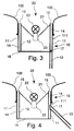
- FIG. 3 shows a cross section corresponding to FIG. 1 another embodiment.
- the power supply i.e. for example the cables 24 and 25 and the battery 26, omitted for clarity.
- the 3 shown in Fig. differs from the embodiment shown in Fig. 1 in that the bottom part 16 is annular.
- the bottom part 16 extends between the lower end of the outer part 11 and the lower end of the inner part 12.
- the inner part 12 enclosed area is open.
- the version and the back of the reflector 21 freely accessible from below.
- Internal thread can be provided by means of which the closure head a bracket can be screwed. Since the version 23 for the lamp 22 is freely accessible from below, any one Power supply can be easily connected to the socket.
- a handle on the locking head be arranged in which batteries are accommodated.
- batteries For one easy battery replacement could be at the bottom of the Handles a bayonet catch with a circuit board be provided, which are electrically connected to the socket 23 is when the bayonet lock is closed to the To provide power supply.
- FIG. 4 shows a cross section corresponding to FIG. 1 another embodiment of the closure head according to the invention. For the sake of clarity, it is the same as that shown in FIG. 3 Locking head omitted the power supply for the socket 23.
- the embodiment of Fig. 4 differs of the embodiment shown in Figures 1 and 2 in that the gas inlet 13 is not at the bottom part 16, but is arranged in the outer part 13.
- the gas inlet 13 is designed as a tubular part. One end of the tubular Part is connected to the gas supply channel 14.
- a check valve 17 prevents that in the balloon 100 pressurized gas through the gas inlet 13 into the environment emanates.
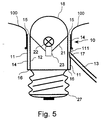
- FIG. 5 shows a cross section corresponding to FIG. 1 another embodiment of the closure head according to the invention.
- the one shown in Fig. 5 Closure head has a lamp screw base 27.
- the size of the lamp screw base 27 is the one for example lamp screw holders commonly used for inside or outside surfaces adapted and can be chosen freely.
- the lamp screw base can be used as an E27 or E14 base be trained.
- the breech head with a wound on it Ballon 100 can be placed in an external lamp holder be screwed in, which are connected to an external power source is.
- the closure head shown in FIG. 5 also differs from the closure head shown in Figures 1 and 2 in that a transparent above the lamp Cap 18 is provided.
- the transparent cap 18 is connected flush with the inner part 12. Compared to that in 7 of the closure head shown in EP 0 241 452 B1 Advantage of the invention particularly clear, because the closure head according to the invention due to the double cylinder structure from outer part 11 and inner part 12 through openings Neither in the reflector 21 nor in the cap 18 are necessary.
- this can Gas inlet also closed only by the check valve 17 Opening may be provided in the outer part 11.
- a cap corresponding to the cap shown in FIG. 5 can also in those shown in FIGS. 1 to 4 or in FIGS closure heads provided in the appended claims become.
- Fig. 6 shows the preferred embodiment of an inventive Locking head 1000, which is associated with a light source 1022 and a tube 1040 is shown cut over an adapter 1030 with a commercially available handle 1026 connected to a flashlight.
- a commercially available handle 1026 connected to a flashlight.
- the handle 1026 are in known manner batteries for the power supply of the Provide light source 1022.
- the locking head 1000 is shown in more detail in FIGS. 7 and 8 shown and is in connection with this figure described.
- the light source 1022 is, for example, a commercially available one Pear, which is provided in a version 1023.
- the version 1023 is arranged in a tube 1040.
- the pipe is 1040 preferably extruded and can also be made from one Can consist of material that is somewhat flexible.
- the extruder tube is used for assembly up to the stop 1019 in the locking head 1000 inserted and preferably fits snugly or non-slip in it.
- a firm connection for example, gluing
- the Tube 1040 leads cables 1024 and 1025 to the commercially available Handle 1026. Instead of a commercially available handle any other power source, of course be used.
- the tube 1040 is connected to a commercially available handle adapted adapter connected to the handle 1026.
- the Adapter 1030 fits the pipe with a precise fit. With its thread In 1031 it is screwed into the handle.
- At the bottom of the Adapters are suitable contacts for connecting to the in the handle to insert batteries provided.
- a switch can also be provided on the adapter.
- FIG. 7 shows a section of the first part 1001 of the one in FIG. 6 shown closure head 1000. It preferably has one cylindrical outer wall 1011, on the surface 1111 a balloon according to FIGS. 1 to 5 are raised can.
- the outer wall 1011 preferably faces those in FIG. 7 a widening at the top to prevent the To prevent balloons from surface 1111.
- the first part 1001 also has an inner wall 1012 that defines a passage 1112 defined by the locking head 1000.
- the inner wall 1012 connects to the outer wall 1011.
- the Inner wall 1012 arranged concentrically with the outer wall 1011.
- the inner wall preferably has a cylindrical shape.
- the inner wall 1012 can any shape give that is adapted to the light source to be introduced.
- the outer wall 1011 can also have any shape as long as it has a surface on which the Balloon can be applied airtight.
- a stop 1019 is provided on the inner wall 1012 through a passage formed by the inner wall 1012 protruding projection is formed. With the stop 1019 is a defined positioning of the in the passage guaranteed light source to be introduced.
- the second part 1002 has a cap 1018 to which a circular disk-shaped wall 1018A connects.
- the cap 1018 preferably has a transparent dome.
- steps 1018B and 1018C provided an exact positioning of the second Guarantee part 1002 on in the first part 1001, because that second part 1002 with the thicker part of wall 1018A in the Opening between the outer wall 1011 and the inner wall 1012 engages while the thin area of wall 1018A is on the Outer wall 1011 and the inner wall 1012 rests.
- steps 1018B and 1018C provided an exact positioning of the second Guarantee part 1002 on in the first part 1001, because that second part 1002 with the thicker part of wall 1018A in the Opening between the outer wall 1011 and the inner wall 1012 engages while the thin area of wall 1018A is on the Outer wall 1011 and the inner wall 1012 rests.
- the wall Breakthroughs are provided to prevent air leakage into the 1018A Ensure inside of the balloon.
- the first part 1001 is preferably with the second part 1002 hermetically connected.
- this can be done by a Glue between the cap 1018 and the inner wall 1012 happen.
- the light source 1022 could also be used by inserting into the passage 1112 of the interior from the Locking head 1000 inflated balloons against the environment seal.
- this has the disadvantage that when removing the Light source from the shutter head the air from inside the Balloons escape. Therefore, it is preferred that an airtight Connection between the second part 1002 and the first part 1001 at least between the inner wall 1012 and the cap 1018 is trained.
- a better connection could also be made the outer wall 1011 with the edge of the wall 1018A in the area of Level 1018B glued.
- the closure head 1000 has one in the outer wall 1011 Gas inlet 1013 on. 6, the locking head is 1000 in Connection shown with other parts.
- the outer wall 1011 in the area of the gas inlet 1013 closable filler neck injected or with the Outer wall 1011 connected airtight (for example by a Bonding).
- the filler neck is closed in the illustrated embodiment with a commercially available elastic stopper.
- the invention also relates to a closure head according to the Claims 16 to 19 with one or more features is further developed according to claims 1 to 15. As well the invention also relates to a closure head according to one of the Claims 1 to 15, according to one or more features of claims 16 to 19 is developed.
- the described locking heads are for example commercially available, translucent gas balloons, such as toy air balloons, Balloons for advertising and decorative purposes etc., usable.
- the closure head is preferably used as an injection molded part manufactured.
Abstract
Description
Die Erfindung betrifft einen Verschlußkopf für einen mit Gas aufblasbaren Ballon gemäß dem Oberbegriff von Anspruch 1.The invention relates to a closure head for a gas inflatable balloon according to the preamble of claim 1.
Ein derartiger Verschlußkopf ist aus der EP 0 241 452 B1
bekannt. Der in Fig. 8 der EP 0 241 452 B1 gezeigte
Verschlußkopf weist einen Gaszuführkanal auf, der zwischen dem
Gehäuse 7 und dem Reflektor 15 ausgebildet ist. Der Austritt
des Gaszuführkanals wird durch Durchtrittsöffnungen 19 in den
Reflektor 5 gebildet. Da die Durchtrittsöffnungen in dem
Reflektor ausgebildet sind, können sie nicht beliebig
vergrößert werden, um einen hinreichenden Strömungsquerschnitt
für das Aufblasen des Ballons zur Verfügung zu stellen, ohne
die Reflektionsfähigkeit des Reflektors zu beeinträchtigen.
Außerdem sind für die Herstellung der Durchtrittsöffnungen
zusätzliche Arbeitsvorgänge notwendig.Such a closure head is known from EP 0 241 452 B1
known. The one shown in Fig. 8 of EP 0 241 452 B1
Breech head has a gas supply channel that between the
Housing 7 and the
Der Erfindung liegt daher die Aufgabe zugrunde, den Verschlußkopf gemäß dem Oberbegriff von Anspruch 1 derart weiterzubilden, daß ein beliebiger Strömungsquerschnitt für den Gaszuführkanal zur Verfügung gestellt werden kann, ohne die Funktion der übrigen Komponenten zu beeinträchtigen. The invention is therefore based on the object, the closure head to further develop according to the preamble of claim 1, that any flow cross section for the Gas supply channel can be made available without the Impair the function of the other components.
Eine weitere Aufgabe der vorliegenden Erfindung ist es, einen Verschlußkopf gemäß dem Oberbegriff von Anspruch 1 derart weiterzubilden, daß er einfach und kostengünstig hergestellt werden kann.Another object of the present invention is to provide a Locking head according to the preamble of claim 1 such to further develop that it is simple and inexpensive to manufacture can be.
Diese Aufgaben werden mit einem Verschlußkopf gemäß den Merkmalen
von Anspruch 1 bzw. 15 gelöst. Vorteilhafte Ausgestaltungen
der Erfindung sind in den abhängigen Ansprüchen angegeben.These tasks are performed with a locking head according to the features
of
Gemäß Anspruch 1 weist der Verschlußkopf neben einem rohrförmigen Außenteil, auf dessen Außenfläche ein Ballon aufgezogen werden kann, ein rohrförmiges Innenteil auf. Zwischen dem Innenteil und dem Außenteil wird der Gaszuführkanal derart definiert, daß der Austritt des Gaszuführkanals für die Zufuhr von Gas zum Aufblasen eines auf dem Verschlußkopf aufgezogenen Ballons zwischen dem Innenteil und dem Außenteil angeordnet ist. Da die Halterung für die Lichtquelle innerhalb des Innenteils angeordnet ist, kann der Strömungsquerschnitt des Austritts einfach durch Vergrößern des Außenteils vergrößert werden, ohne die Funktion und Bauweise der Halterung zu beeinflußen.According to claim 1, the closure head has a tubular Outer part, on the outer surface of which a balloon is drawn can be a tubular inner part. Between the The inner part and the outer part of the gas supply channel defines that the exit of the gas supply channel for the supply of gas to inflate one drawn on the breech head Balloons arranged between the inner part and the outer part is. Since the holder for the light source inside the Is arranged internally, the flow cross section of the Exit simply enlarged by enlarging the outer part without the function and design of the bracket influence.
Vorzugsweise sind das Innenteil und/oder das Außenteil zylinderförmig ausgebildet, um eine einfache und kostengünstige Herstellung des Verschlußkopfes zu gewährleisten.The inner part and / or the outer part are preferably cylindrical trained to be a simple and inexpensive Ensure manufacture of the closure head.
Das Außenteil kann auch konisch verjüngt ausgebildet sein, damit der Ballon leichter auf dem Verschlußkopf aufgezogen werden kann.The outer part can also be conically tapered, so that the balloon can be pulled up more easily on the closure head can be.
Bei bestimmten Ballonsorten kann es auch vorteilhaft sein, das Außenteil derart konisch auszubilden, daß der größte Durchmesser des Außenteils im Bereich des Austritts des Gaszuführkanals ist, um ein Abrutschen des Ballons von dem Verschlußkopf zuverlässig zu verhindern. With certain types of balloons, it can also be advantageous that Conical outer part so that the largest diameter of the outer part in the area of the outlet of the gas supply channel is to prevent the balloon from slipping off the closure head reliably prevent.
In dem Außenteil kann vorteilhafterweise auch eine Nut vorgesehen sein, die als Halterung für einen Abschnitt des Ballonhalses dient.A groove can advantageously also be provided in the outer part be provided as a holder for a portion of the Balloon neck serves.
Vorzugsweise sind das Innenteil und das Außenteil konzentrisch zueinander angeordnet, um eine einfache und kostengünstige Herstellung zu gewährleisten. Diese Anordnung hat den weiteren Vorteil, daß der Austritt einen kreisförmigen Querschnitt mit einem damit verbundenen gleichbleibenden Strömungsquerschnitt aufweist.The inner part and the outer part are preferably concentric arranged to each other for easy and inexpensive manufacture to ensure. This arrangement has the other Advantage that the exit has a circular cross section an associated constant flow cross-section having.
Vorteilhafterweise ist der Lufteinlaß für den Gaszuführkanal ein rohrförmiges Teil, dessen Achse parallel zu der Achse des rohrförmigen Außenteils verläuft. Da diese beiden Teile parallel zueinander verlaufen, wird die Herstellung einfach und kostengünstig.The air inlet for the gas supply duct is advantageous a tubular part, the axis of which is parallel to the axis of the tubular outer part runs. Because these two parts run parallel to each other, manufacturing is easy and inexpensive.
Gemäß Anspruch 15 weist der Verschlußkopf neben einer Außenwand,
auf dessen Oberfläche ein Ballon aufgezogen werden kann,
eine Innenwand auf, die einen Durchgang definiert, in den eine
Lichtquelle eingeschoben werden kann. Der Durchgang ist
gegenüber den Innenraum des Ballons mit einer Kappe, die
vorzugsweise eine Kuppel aus transparenten Material aufweist,
verschlossen. Da der Gaszuführkanal zwischen der Innenwand und
der Außenwand definiert ist, kann der Strömungsquerschnitt des
Austritts einfach durch Vergrößern von Durchbrüchen vergrößert
werden, ohne die Funktion und Bauweise der Lichtquelle zu
beeinflussen.According to
Jede geeignete Lichtquelle kann in Verbindung mit dem erfindungsgemäßen
Verschlußkopf verwendet werden. Gemäß einem
besonders einfachen Aufbau weist der Verschlußkopf zwei Teile
auf, wobei das erste Teil die Außenwand und die Innenwand
bildet, und das zweite Teil aus einem im wesentlichen durchsichtigen
Material ausgebildet ist, das den von der Innenwand
definierten Durchgang gegenüber dem Inneren von dem Ballon
abdichtet. Die Lichtquelle kann in dem vorzugsweise als Kappe
ausgebildeten zweiten Teil angeordnet werden, indem sie in den
von der Innenwand 1012 definierten Durchgang eingebracht wird.
Vorzugsweise ist das zweite Teil mit der Innenwand verklebt,
um eine luftdichte Verbindung herzustellen.Any suitable light source can be used in conjunction with the invention
Closure head can be used. According to one
particularly simple construction, the closure head has two parts
on, the first part the outer wall and the inner wall
forms, and the second part of a substantially transparent
Material is formed that from the inner wall
defined passage towards the inside of the balloon
seals. The light source can preferably be a cap
trained second part can be arranged by in the
is introduced from the
Der Verschlußkopf gemäß Anspruch 16 mit den in den unabhängigen
Ansprüchen angegebenen Merkmalen stellt die bevorzugte
Ausführung der Erfindung dar. Dieser Verschlußkopf kann mit
einem Leuchtkopf kombiniert werden, der vorzugsweise auf ein
Extruderrohr aufgesetzt ist, das mit einem Adapter an einen
handelsüblichen Handgriff für Batterien, beispielsweise einen
Handgriff einer Stabtaschenlampe, angeschlossen werden kann.The closure head according to
Im folgenden wird die Erfindung anhand der in den Zeichnungen gezeigten Ausführungsbeispiele näher beschrieben.
- Fig. 1
- zeigt einen Querschnitt entlang der Linie I-I von Fig. 2 von einem Verschlußkopf gemäß einem ersten Ausführungsbeispiel, auf den ein Ballon aufgezogen ist.
- Fig. 2
- zeigt einen Querschnitt von dem im Fig. 1 gezeigten Verschlußkopf entlang der Linie II-II ohne aufgezogenen Ballon.
- Fig. 3
- zeigt einen der Fig. 1 entsprechenden Querschnitt eines weiteren Ausführungsbeispiels der vorliegenden Erfindung.
- Fig. 4
- zeigt einen der Fig. 1 entsprechenden Querschnitt eines weiteren Ausführungsbeispiels der vorliegenden Erfindung.
- Fig. 5
- zeigt einen der Fig. 1 entsprechenden Querschnitt eines weiteren Ausführungsbeispiels der vorliegenden Erfindung.
- Fig. 6
- zeigt die bevorzugte erfindungsgemäße Ausführung eines Verschlußkopfes in Verbindung mit einer Lichtquelle, einem Rohr, einem Adapter und einem handelsüblichen Handgriff für Batterien in einer Schnittdarstellung.
- Fig. 7
- zeigt eine geschnittene Darstellung des ersten Teils des Verschlußkopfes von Fig. 6.
- Fig. 8
- zeigt eine geschnittene Darstellung des zweiten Teils des Verschlußkopfes von Fig. 6.
- Fig. 9
- zeigt eine geschnittene Darstellung des Adapters von Fig. 6.
- Fig. 1
- shows a cross section along the line II of Fig. 2 of a closure head according to a first embodiment, on which a balloon is mounted.
- Fig. 2
- shows a cross section of the closure head shown in Fig. 1 along the line II-II without the balloon being inflated.
- Fig. 3
- shows a cross section corresponding to FIG. 1 of a further exemplary embodiment of the present invention.
- Fig. 4
- shows a cross section corresponding to FIG. 1 of a further exemplary embodiment of the present invention.
- Fig. 5
- shows a cross section corresponding to FIG. 1 of a further exemplary embodiment of the present invention.
- Fig. 6
- shows the preferred embodiment of a closure head according to the invention in connection with a light source, a tube, an adapter and a commercially available handle for batteries in a sectional view.
- Fig. 7
- FIG. 6 shows a sectional illustration of the first part of the closure head from FIG. 6.
- Fig. 8
- shows a sectional view of the second part of the closure head of Fig. 6th
- Fig. 9
- shows a sectional view of the adapter of FIG. 6.
Fig. 1 zeigt einen Querschnitt von dem bevorzugten Ausführungsbeispiel
der Erfindung. Auf die Außenfläche 111 des zylinderförmigen
Außenteils 11 ist ein Ballon 100 aufgezogen. Das
zylinderförmige Außenteil 11 schließt das zylinderförmige
Innenteil 12 ein. Zwischen dem Außenteil 11 und dem Innenteil
12 ist der Gaszuführkanal 14 definiert. Gas, d.h. Luft oder ein
kommerziell erhältliches Gas, wie z.B. Helium oder Wasserstoff
usw., kann über den Gaseinlaß 13 in den Gaszuführkanal 14
eingeleitet werden. Das Rückschlagventil 17 verhindert, daß das
in dem Ballon 100 unter Druck stehende Gas über den Gaseinlaß
13 in die Umgebung ausströmt. Das Außenteil 11 ist mit dem
Innenteil 12 über die Bodenplatte 16 verbunden. In der
Bodenplatte 16 ist in dem Bereich des Gaseinlasses 13 eine
Öffnung für die Gaszufuhr vorgesehen. An der Öffnung ist das
Rückschlagventil 17 vorgesehen. Der Gaszuführkanal 14 weist
einen Austritt 15 mit einem kreisringförmigen Querschnitt auf.Fig. 1 shows a cross section of the preferred embodiment
the invention. On the
Innerhalb des Innenteils 12 ist die Halterung 20 für eine
schematisch dargestellte Lampe 22 angeordnet. Die Halterung
weist einen Reflektor 21 auf, in dessen Zentrum eine schematisch
dargestellte Fassung 23 für eine Lampe 22 angeordnet ist.
Der Reflektor 21 ist bei dem Ausführungsbeispiel von Fig. 1
gasdicht mit dem Innenteil 12 verbunden.Within the
Die Stromversorgung der Lampe erfolgt über die beiden Kabel 24
und 25, die mit einer Batterie 26 verbunden sind. Alternativ
kann die Stromversorgung auch über einen direkten Anschluß von
Batterien erfolgen. Weiterhin kann die Stromversorgung auch wie
bei herkömmlichen Lichterketten erfolgen.The lamp is supplied with power via the two
Fig. 2 zeigt einen Querschnitt längs der Linie II-II des in
Fig. 1 gezeigten Verschlußkopfes. Der Verschlußkopf von Fig.
2 ist ohne aufgezogenen Ballon dargestellt. Die Blickrichtung
entspricht einer Ansicht des in Fig. 1 gezeigten Verschlußkopfes
von oben. Innerhalb des Außenteils 11 ist das Innenteil
12 angeordnet. Zwischen dem Außenteil 11 und dem Innenteil 12
ist der Gaszuführkanal 14 definiert. Der Austritt 15 des Gaszuführkanals
14 hat einen kreisringförmigen Querschnitt.
Innerhalb des Innenteils 12 ist der Reflektor 21 angeordnet.
In der Mitte des Reflektors 21 ist die Lampe 22 angeordnet. Der
Gaseinlaß 13 ist schematisch auf der rechten Seite dargestellt.
Übersichtshalber wurde das Rückschlagventil 17 nicht dargestellt.Fig. 2 shows a cross section along the line II-II of the in
Fig. 1 shown closure head. The closure head of Fig.
2 is shown without the balloon inflated. The direction of view
corresponds to a view of the closure head shown in FIG. 1
from above. Inside the
Bei dem in Fig. 1 dargestellten Ausführungsbeispiel kann der
Gaseinlaß auch durch eine einfache Öffnung in dem Bodenteil 16
ausgebildet sein, die mit dem zwischen dem Innenteil 12 und dem
Außenteil 11 ausgebildeten Gaszuführkanal 14 in Verbindung
steht und durch das Rückschlagventil 17 verschlossen ist.In the embodiment shown in Fig. 1, the
Gas inlet also through a simple opening in the
In den Figuren 3 und 4 werden weitere Ausführungsbeispiele des erfindungsgemäßen Verschlußkopfes gezeigt. Um unnötige Wiederholungen zu vermeiden, wird im folgenden nur auf die Unterschiede zu dem in den Figuren 1 und 2 gezeigten Ausführungsbeispiel eingegangen. Auf gleiche Teile wird mit gleichen Bezugszeichen Bezug genommen. In the figures 3 and 4 further embodiments of the closure head according to the invention shown. To unnecessary Avoiding repetitions is only discussed below Differences from the exemplary embodiment shown in FIGS. 1 and 2 received. On equal parts with same reference numerals.
Fig. 3 zeigt einen der Fig. 1 entsprechenden Querschnitt eines
weiteren Ausführungsbeispiels. Bei diesem Ausführungsbeispiel
ist die Stromversorgung, d.h. beispielsweise die Kabel 24 und
25 sowie die Batterie 26, übersichtlichshalber weggelassen. Das
in Fig. 3 gezeigte Ausführugnsbeispiel unterscheidet sich von
dem in Fig. 1 gezeigten Ausführungsbeispiel dahingehend, daß
das Bodenteil 16 kreisringförmig ausgebildet ist. Das Bodenteil
16 erstreckt sich zwischen dem unteren Ende des Außenteils 11
und dem unteren Ende des Innenteils 12. Der vom Innenteil 12
eingeschlossene Bereich ist offen. Daher ist die Fassung und
die Rückseite des Reflektors 21 von unten frei zugänglich. Beispielsweise
könnte an der Innenseite des Innenteils 12 ein
Innengewinde vorgesehen sein, mittels dem der Verschlußkopf auf
eine Halterung geschraubt werden kann. Da die Fassung 23 für
die Lampe 22 von unten frei zugänglich ist, kann eine beliebige
Stromversorgung leicht an der Fassung angeschlossen werden.
Beispielsweise könnte ein Haltegriff an dem Verschlußkopf
angeordnet werden, in den Batterien aufgenommen sind. Für einen
leichten Austausch der Batterien könnte an dem Boden des
Haltegriffs ein Bajonettverschluß mit einer Leiterplatte
vorgesehen sein, die elektrisch mit der Fassung 23 verbunden
ist, wenn der Bajonettverschluß geschlossen ist, um die
Stromversorgung bereitzustellen.FIG. 3 shows a cross section corresponding to FIG. 1
another embodiment. In this embodiment
is the power supply, i.e. for example the
Fig. 4 zeigt einen der Fig. 1 entsprechenden Querschnitt eines
weiteren Ausführungsbeispiels des erfindungsgemäßen Verschlußkopfes.
Übersichtshalber ist wie bei dem in Fig. 3 gezeigten
Verschlußkopf die Stromversorgung für die Fassung 23 weggelassen.
Das Ausführungsbeispiel von Fig. 4 unterscheidet sich
von dem in den Figuren 1 und 2 dargstellten Ausführungsbeispiel
dahingehend, daß der Gaseinlaß 13 nicht beim Bodenteil 16,
sondern in dem Außenteil 13 angeordnet ist. Der Gaseinlaß 13
ist als rohrförmiges Teil ausgebildet. Ein Ende des rohrförmigen
Teils steht mit dem Gaszuführkanal 14 in Verbindung.
Ein Rückschlagventil 17 verhindert, daß das in dem Ballon 100
unter Druck stehende Gas über den Gaseinlaß 13 in die Umgebung
ausströmt. FIG. 4 shows a cross section corresponding to FIG. 1
another embodiment of the closure head according to the invention.
For the sake of clarity, it is the same as that shown in FIG. 3
Locking head omitted the power supply for the
Fig. 5 zeigt einen der Fig. 1 entsprechenden Querschnitt eines
weiteren Ausführungsbeispiels des erfindungsgemäßen Verschlußkopfes.
Übersichtshalber sind die Einzelheiten der Stromversorgung
für die Fassung 23 weggelassen. Der in Fig. 5 gezeigte
Verschlußkopf weist einen Lampenschraubensockel 27 auf. Die
Größe des Lampenschraubsockels 27 sind diejenige zum Beispiel
für Innen- oder Außenfläche gebräuchliche Lampenschraubfassungen
angepaßt und kann frei gewählt werden. Beispielsweise
kann der Lampenschraubsockel als E27-Sockel oder E14-Sockel
ausgebildet sein. Der Verschlußkopf mit einem darauf aufgezogenen
Ballon 100 kann in eine externe Lampenschraubfassung
eingeschraubt werden, die an eine externe Stromquelle angeschlossen
ist.FIG. 5 shows a cross section corresponding to FIG. 1
another embodiment of the closure head according to the invention.
For the sake of clarity, the details of the power supply are
omitted for the
Weiterhin unterscheidet sich der in Fig. 5 gezeigte Verschlußkopf
von dem in den Figuren 1 und 2 gezeigten Verschlußkopf
dahingehend, daß oberhalb der Lampe eine transparente
Kappe 18 vorgesehen ist. Die transparente Kappe 18 ist
bündig mit dem Innenteil 12 verbunden. Im Vergleich zu dem in
Fig. 7 der EP 0 241 452 B1 gezeigten Verschlußkopf wird der
Vorteil der Erfindung besonders deutlich, weil bei dem
erfindungsgemäßen Verschlußkopf aufgrund der Doppelzylinderstruktur
aus Außenteil 11 und Innenteil 12 Durchtrittsöffnungen
weder in dem Reflektor 21 noch in der Kappe 18 notwendig sind.The closure head shown in FIG. 5 also differs
from the closure head shown in Figures 1 and 2
in that a transparent above the
Wie bei dem in Fig. 1 gezeigten Ausführungsbeispiel kann das
Gaseinlaß auch nur eine durch das Rückschlagventil 17 verschlossene
Öffnung in dem Außenteil 11 vorgesehen sein.As with the embodiment shown in FIG. 1, this can
Gas inlet also closed only by the
Eine der in Fig. 5 gezeigten Kappe entsprechende Kappe kann auch bei den in den Figuren 1 bis 4 gezeigten bzw. den in den beigefügten Ansprüchen beschriebenen Verschlußköpfen vorgesehen werden.A cap corresponding to the cap shown in FIG. 5 can also in those shown in FIGS. 1 to 4 or in FIGS closure heads provided in the appended claims become.
Fig. 6 zeigt die bevorzugte Ausführung eines erfindungsgemäßen
Verschlußkopfes 1000, der im Zusammenhang mit einer Lichtquelle
1022 und einem Rohr 1040 geschnitten dargestellt ist, das über
einen Adapter 1030 mit einem handelsüblichen Handgriff 1026
einer Taschenlampe verbunden ist. In dem Handgriff 1026 sind
auf bekannte Weise Batterien für die Stromversorgung der
Lichtquelle 1022 vorzusehen.Fig. 6 shows the preferred embodiment of an
Der Verschlußkopf 1000 ist genauer in den Figuren 7 und 8
gezeigt und wird im Zusammenhang mit diesem Figuren
beschrieben.The locking
Die Lichtquelle 1022 ist beispielsweise eine handelsübliche
Birne, die in einer Fassung 1023 vorgesehen ist. Die Fassung
1023 ist in einem Rohr 1040 angeordnet. Das Rohr 1040 ist
vorzugsweise extrudiert und kann je nach Wunsch auch aus einem
Material bestehen kann, das etwas flexibel ist. Das Extruderrohr
wird zur Montage bis zum Anschlag 1019 in den Verschlußkopf
1000 eingeführt und sitzt vorzugsweise paßgenau bzw.
rutschfest in ihm. Vorzugsweise sollte eine feste Verbindung
(zum Beispiel eine Verklebung) nicht zwischen dem Rohr 1040 und
dem Verschlußkopf 1000 ausgebildet werden, weil es bevorzugt
wird, daß der Verschlußkopf 1000 abziehbar bleibt. Durch das
Rohr 1040 führen Kabeln 1024 und 1025 zu dem handelsüblichen
Handgriff 1026. Statt eines handelsüblichen Handgriffs kann
selbstverständlich auch eine beliebige andere Stomquelle
verwendet werden.The
Das Rohr 1040 ist über einen an den handelsüblichen Handgriff
angepaßten Adapter mit dem Handgriff 1026 verbunden. Der
Adapter 1030 nimmt das Rohr paßgenau auf. Mit seinem Gewinde
1031 wird er in den Handgriff eingedreht. An der Unterseite des
Adapters sind geeignete Kontakte für die Verbindung mit dem in
den Handgriff einzubringen Batterien vorgesehen. Vorzugsweise
kann auch ein Einschalter an dem Adapter vorgesehen sein.The
Fig. 7 zeigt eine Schnitt des ersten Teils 1001 des in Fig. 6
gezeigten Verschlußkopfes 1000. Es weist eine vorzugsweise
zylinderförmige Außenwand 1011 auf, auf deren Oberfläche 1111
ein Ballon entsprechend den Fig. 1 bis 5 aufgezogen werden
kann. Die Außenwand 1011 weist vorzugsweise in den in Fig. 7
oberen Bereich eine Aufweitung auf, um ein Abrutschen des
Ballons von der Oberfläche 1111 zu verhindern. Das erste Teil
1001 weist ferner eine Innenwand 1012 auf, die einen Durchgang
1112 durch den Verschlußkopf 1000 definiert. Ferner weist das
erste Teil 1001 eine Bodenwand 1016 auf, die die Innenwand 1012
mit der Außenwand 1011 verbindet. Vorzugsweise ist die
Innenwand 1012 konzentrisch zu der Außenwand 1011 angeordnet.
Vorzugsweise weist die Innenwand eine zylindrische Gestalt auf.FIG. 7 shows a section of the
Es ist möglich, der Innenwand 1012 eine beliebige Form zu
geben, die an die einzubringende Lichtquelle angepasst ist.
Ebenso kann auch die Außenwand 1011 eine beliebige Form
aufweisen, solange sie eine Oberfläche aufweist, auf der der
Ballon luftdicht aufgebracht werden kann.It is possible to shape the
An der Innenwand 1012 ist ein Anschlag 1019 vorgesehen, der
durch einen in den von der Innenwand 1012 gebildeten Durchgang
hineinragenden Vorsprung gebildet ist. Mit dem Anschlag 1019
wird eine definierte Positionierung der in den Durchgang
einzuführenden Lichtquelle gewährleistet.A
Fig. 8 zeigt das zweite Teil 1002 des Verschlußkopfes 1000 von
Fig. 6. Das zweite Teil 1002 weist eine Kappe 1018 auf, an die
sich ein kreisscheibenförmiger Wand 1018A anschließt. Die Kappe
1018 weist vorzugsweise eine transparente Kuppel auf. An der
kreisscheibenförmigen Wand 1018A sind unten Stufen 1018B und
1018C vorgesehen, die eine exakte Positionierung des zweiten
Teils 1002 auf in dem ersten Teil 1001 gewährleisten, weil das
zweite Teil 1002 mit dem dickeren Teil der Wand 1018A in die
Öffnung zwischen der Außenwand 1011 und der Innenwand 1012
eingreift, während der dünne Bereich der Wand 1018A auf der
Außenwand 1011 und der Innenwand 1012 aufliegt. In der Wand
1018A sind Durchbrüche vorgesehen, um einen Luftaustritt in das
Innere des Ballons zu gewährleisten. 8 shows the
Das erste Teil 1001 ist vorzugsweise mit dem zweiten Teil 1002
luftdicht verbunden. Beispielsweise kann das durch eine
Verklebung zwischen der Kappe 1018 und der Innenwand 1012
geschehen. Alternativ könnte jedoch auch die Lichtquelle 1022
durch das Einführen in den Durchgang 1112 des Innere aus dem
Verschlußkopf 1000 aufgezogenen Ballons gegenüber der Umgebung
abdichten. Das hat jedoch den Nachteil, das beim Entfernen der
Lichtquelle aus dem Verschlußkopf die Luft aus dem Inneren des
Ballons entweicht. Daher ist es bevorzugt, daß eine luftdichte
Verbindung zwischen dem zweiten Teil 1002 und dem ersten Teil
1001 zumindest zwischen der Innenwand 1012 und der Kappe 1018
ausgebildet ist. Zusätzlich könnte auch eine bessere Verbindung
die Außenwand 1011 mit dem Rand der Wand 1018A im Bereich der
Stufe 1018B verklebt sein.The
Der Verschlußkopf 1000 weist in der Außenwand 1011 einen
Gaseinlass 1013 auf. In Fig. 6 ist der Verschlußkopf 1000 in
Zusammenhang mit weiteren Teilen gezeigt. Beispielsweise kann
an die Außenwand 1011 im Bereich des Gaseinlasses 1013 ein
verschließbarer Einfüllstutzen eingespritzt oder mit der
Außenwand 1011 luftdicht verbunden (beispielsweise durch eine
Verklebung) werden. Der Verschluß des Einfüllstutzen erfolgt
im dargestellten Ausführungsbeispiel mit einem handelsüblichen
elastischen Stopfen.The
Die Erfindung betrifft auch einen Verschlußkopf gemäß den
Ansprüchen 16 bis 19, der mit einem oder mehreren Merkmalen
gemäß der Ansprüche 1 bis 15 weitergebildet ist. Ebenso
betrifft die Erfindung auch ein Verschlußkopf gemäß einem der
Ansprüche 1 bis 15, der mit einem oder mehreren Merkmalen gemäß
der Ansprüche 16 bis 19 weitergebildet ist.The invention also relates to a closure head according to the
Die beschriebenen Verschlußköpfe sind beispielsweise für handelsübliche, durchscheinende Gasballons, wie SpielzeugLuftballons, Ballons für Werbe- und Dekorationszwecke usw., verwendbar. Der Verschlußkopf wird vorzugsweise als Spritzgußteil hergestellt.The described locking heads are for example commercially available, translucent gas balloons, such as toy air balloons, Balloons for advertising and decorative purposes etc., usable. The closure head is preferably used as an injection molded part manufactured.
Claims (21)
gekennzeichnet durch
marked by
gekennzeichnet durch
marked by
wobei das erste Teil die Außenwand (1011), die Innenwand (1012) und eine Bodenwand (1016) umfaßt, die die Außenwand (1011) mit der Innenwand (1012) auf der der Kappe (1018) gegenüberliegenden Seite verbindet, und
wobei das zweite Teil die Kappe (1018) umfaßt, die vorzugsweise in der Innenwand (1012) luftdicht verbunden ist.The closure head (1000) according to claim 15, which has a first part (1001) and a second part (1002),
the first part comprising the outer wall (1011), the inner wall (1012) and a bottom wall (1016) connecting the outer wall (1011) to the inner wall (1012) on the side opposite the cap (1018), and
the second part comprising the cap (1018), which is preferably connected airtight in the inner wall (1012).
Applications Claiming Priority (4)
| Application Number | Priority Date | Filing Date | Title |
|---|---|---|---|
| DE1999121789 DE19921789A1 (en) | 1999-05-11 | 1999-05-11 | Closure head for balloon inflatable with gas has holder arranged inside tubular inner part, whereby gas delivery channel outlet is formed between outer part and inner part |
| DE19921789 | 1999-05-11 | ||
| DE2000109553 DE10009553A1 (en) | 2000-02-29 | 2000-02-29 | Closure head for balloon inflatable with gas has holder arranged inside tubular inner part, whereby gas delivery channel outlet is formed between outer part and inner part |
| DE10009553 | 2000-02-29 |
Publications (2)
| Publication Number | Publication Date |
|---|---|
| EP1052003A2 true EP1052003A2 (en) | 2000-11-15 |
| EP1052003A3 EP1052003A3 (en) | 2003-04-23 |
Family
ID=26004579
Family Applications (1)
| Application Number | Title | Priority Date | Filing Date |
|---|---|---|---|
| EP00109818A Withdrawn EP1052003A3 (en) | 1999-05-11 | 2000-05-09 | Closure head for a gas inflatable balloon |
Country Status (1)
| Country | Link |
|---|---|
| EP (1) | EP1052003A3 (en) |
Cited By (1)
| Publication number | Priority date | Publication date | Assignee | Title |
|---|---|---|---|---|
| AT501446A1 (en) * | 2004-09-21 | 2006-09-15 | Andreas Braunboeck | APPARATUS FOR RECORDING AN INFLATABLE BALLOON |
Citations (1)
| Publication number | Priority date | Publication date | Assignee | Title |
|---|---|---|---|---|
| EP0241452B1 (en) | 1984-10-29 | 1992-05-13 | HIERAT, Alexander | Additional device for inflatable gas balloon |
Family Cites Families (7)
| Publication number | Priority date | Publication date | Assignee | Title |
|---|---|---|---|---|
| US1229794A (en) * | 1916-07-20 | 1917-06-12 | Arthur Salzer | Illuminated toy balloon and lighting effect. |
| US1832408A (en) * | 1930-05-13 | 1931-11-17 | John H Modes | Means for producing novel effects in decoration and the like |
| US3536906A (en) * | 1968-10-28 | 1970-10-27 | Miner Ind Inc | Illuminated balloon device |
| DE2904514A1 (en) * | 1979-02-07 | 1980-08-21 | Anton Szollmann | VALVE FOR CHILDREN'S BALLOONS |
| DE3015962A1 (en) * | 1980-04-25 | 1981-11-05 | Anton 7500 Karlsruhe Szollmann | Inflatable balloon holder and illuminator - has rod-shaped lamp without optics, plug for balloon inflation and non-return valve coupled to tube from plug |
| US4542445A (en) * | 1984-01-03 | 1985-09-17 | Louis J. Castaldo | Electric light balloon |
| EP0179949A1 (en) * | 1984-10-29 | 1986-05-07 | Robert Neumeier | Complementory device for a balloon |
-
2000
- 2000-05-09 EP EP00109818A patent/EP1052003A3/en not_active Withdrawn
Patent Citations (1)
| Publication number | Priority date | Publication date | Assignee | Title |
|---|---|---|---|---|
| EP0241452B1 (en) | 1984-10-29 | 1992-05-13 | HIERAT, Alexander | Additional device for inflatable gas balloon |
Cited By (2)
| Publication number | Priority date | Publication date | Assignee | Title |
|---|---|---|---|---|
| AT501446A1 (en) * | 2004-09-21 | 2006-09-15 | Andreas Braunboeck | APPARATUS FOR RECORDING AN INFLATABLE BALLOON |
| AT501446B1 (en) * | 2004-09-21 | 2008-03-15 | Andreas Braunboeck | DEVICE FOR PLUG INTO INFLATABLE BALLOON |
Also Published As
| Publication number | Publication date |
|---|---|
| EP1052003A3 (en) | 2003-04-23 |
Similar Documents
| Publication | Publication Date | Title |
|---|---|---|
| EP0241452B1 (en) | Additional device for inflatable gas balloon | |
| WO1986003421A1 (en) | Accessory for gas-filled balloon | |
| WO1986005255A1 (en) | Sealing head for a gas balloon | |
| DE3525672C2 (en) | ||
| EP2622261A1 (en) | Arrangement for light emission | |
| EP1052003A2 (en) | Closure head for a gas inflatable balloon | |
| DE10009553A1 (en) | Closure head for balloon inflatable with gas has holder arranged inside tubular inner part, whereby gas delivery channel outlet is formed between outer part and inner part | |
| EP0075839A1 (en) | Electric lamp | |
| EP1108182B1 (en) | Lighting device | |
| EP1253375B1 (en) | Explosion-proof lamp | |
| EP0179949A1 (en) | Complementory device for a balloon | |
| DE19921789A1 (en) | Closure head for balloon inflatable with gas has holder arranged inside tubular inner part, whereby gas delivery channel outlet is formed between outer part and inner part | |
| DE1766713B1 (en) | Laryngoscope with fiberglass light guide | |
| DE202007005888U1 (en) | Lighting device has shielding hollow body accommodating light source, and external hollow body accommodating shielding body, where external body has parts that are detachably connected with each other | |
| DE4411890C2 (en) | Lamp holder for a lamp | |
| DE10253887A1 (en) | Illumination unit with at least one inflated balloon comprises a hollow illumination element which contains at least one light source and is sealed relative to the balloon interior | |
| DE10212353A1 (en) | Illumination device has shade in form of positive pressure flexible membrane body and transparent screening arrangement between light source and shade | |
| DE202012102460U1 (en) | Zoom Flashlight | |
| DE10353893B3 (en) | Holder for inflatable balloon having cupped shape with handle divided by slit in which filling neck of balloon is clamped | |
| DE202015106015U1 (en) | Light-emitting diode module and luminaire with at least one light-emitting diode module | |
| DE202023103963U1 (en) | lamp | |
| AT525611A2 (en) | lighting device | |
| DE60311242T2 (en) | Signaling device for visual location system, e.g. for rescue vehicle in shipping and similar areas | |
| DE2649104A1 (en) | Globe shaped lamp for even illumination - has high intensity bulb shaded by opal hood to provide dazzle-free lighting | |
| DE4420045C2 (en) | Luminaire with a lamp body that completely surrounds the lamp |
Legal Events
| Date | Code | Title | Description |
|---|---|---|---|
| PUAI | Public reference made under article 153(3) epc to a published international application that has entered the european phase |
Free format text: ORIGINAL CODE: 0009012 |
|
| AK | Designated contracting states |
Kind code of ref document: A2 Designated state(s): AT BE CH CY DE DK ES FI FR GB GR IE IT LI LU MC NL PT SE |
|
| AX | Request for extension of the european patent |
Free format text: AL;LT;LV;MK;RO;SI |
|
| PUAL | Search report despatched |
Free format text: ORIGINAL CODE: 0009013 |
|
| AK | Designated contracting states |
Designated state(s): AT BE CH CY DE DK ES FI FR GB GR IE IT LI LU MC NL PT SE |
|
| AX | Request for extension of the european patent |
Extension state: AL LT LV MK RO SI |
|
| STAA | Information on the status of an ep patent application or granted ep patent |
Free format text: STATUS: THE APPLICATION IS DEEMED TO BE WITHDRAWN |
|
| 18D | Application deemed to be withdrawn |
Effective date: 20021203 |