EP1051046A2 - Procédé pour fournir des services de réseau intelligent dans un réseau IP - Google Patents
Procédé pour fournir des services de réseau intelligent dans un réseau IP Download PDFInfo
- Publication number
- EP1051046A2 EP1051046A2 EP20000101611 EP00101611A EP1051046A2 EP 1051046 A2 EP1051046 A2 EP 1051046A2 EP 20000101611 EP20000101611 EP 20000101611 EP 00101611 A EP00101611 A EP 00101611A EP 1051046 A2 EP1051046 A2 EP 1051046A2
- Authority
- EP
- European Patent Office
- Prior art keywords
- network
- gateway
- terminals
- terminal
- server
- Prior art date
- Legal status (The legal status is an assumption and is not a legal conclusion. Google has not performed a legal analysis and makes no representation as to the accuracy of the status listed.)
- Withdrawn
Links
Images


Classifications
-
- H—ELECTRICITY
- H04—ELECTRIC COMMUNICATION TECHNIQUE
- H04L—TRANSMISSION OF DIGITAL INFORMATION, e.g. TELEGRAPHIC COMMUNICATION
- H04L12/00—Data switching networks
- H04L12/64—Hybrid switching systems
- H04L12/6418—Hybrid transport
-
- H—ELECTRICITY
- H04—ELECTRIC COMMUNICATION TECHNIQUE
- H04M—TELEPHONIC COMMUNICATION
- H04M7/00—Arrangements for interconnection between switching centres
- H04M7/006—Networks other than PSTN/ISDN providing telephone service, e.g. Voice over Internet Protocol (VoIP), including next generation networks with a packet-switched transport layer
-
- H—ELECTRICITY
- H04—ELECTRIC COMMUNICATION TECHNIQUE
- H04Q—SELECTING
- H04Q3/00—Selecting arrangements
- H04Q3/0016—Arrangements providing connection between exchanges
- H04Q3/0029—Provisions for intelligent networking
- H04Q3/0045—Provisions for intelligent networking involving hybrid, i.e. a mixture of public and private, or multi-vendor systems
-
- H—ELECTRICITY
- H04—ELECTRIC COMMUNICATION TECHNIQUE
- H04L—TRANSMISSION OF DIGITAL INFORMATION, e.g. TELEGRAPHIC COMMUNICATION
- H04L12/00—Data switching networks
- H04L12/64—Hybrid switching systems
- H04L12/6418—Hybrid transport
- H04L2012/6472—Internet
-
- H—ELECTRICITY
- H04—ELECTRIC COMMUNICATION TECHNIQUE
- H04L—TRANSMISSION OF DIGITAL INFORMATION, e.g. TELEGRAPHIC COMMUNICATION
- H04L12/00—Data switching networks
- H04L12/64—Hybrid switching systems
- H04L12/6418—Hybrid transport
- H04L2012/6475—N-ISDN, Public Switched Telephone Network [PSTN]
-
- H—ELECTRICITY
- H04—ELECTRIC COMMUNICATION TECHNIQUE
- H04Q—SELECTING
- H04Q2213/00—Indexing scheme relating to selecting arrangements in general and for multiplex systems
- H04Q2213/13097—Numbering, addressing
-
- H—ELECTRICITY
- H04—ELECTRIC COMMUNICATION TECHNIQUE
- H04Q—SELECTING
- H04Q2213/00—Indexing scheme relating to selecting arrangements in general and for multiplex systems
- H04Q2213/13103—Memory
-
- H—ELECTRICITY
- H04—ELECTRIC COMMUNICATION TECHNIQUE
- H04Q—SELECTING
- H04Q2213/00—Indexing scheme relating to selecting arrangements in general and for multiplex systems
- H04Q2213/13106—Microprocessor, CPU
-
- H—ELECTRICITY
- H04—ELECTRIC COMMUNICATION TECHNIQUE
- H04Q—SELECTING
- H04Q2213/00—Indexing scheme relating to selecting arrangements in general and for multiplex systems
- H04Q2213/13176—Common channel signaling, CCS7
-
- H—ELECTRICITY
- H04—ELECTRIC COMMUNICATION TECHNIQUE
- H04Q—SELECTING
- H04Q2213/00—Indexing scheme relating to selecting arrangements in general and for multiplex systems
- H04Q2213/13196—Connection circuit/link/trunk/junction, bridge, router, gateway
-
- H—ELECTRICITY
- H04—ELECTRIC COMMUNICATION TECHNIQUE
- H04Q—SELECTING
- H04Q2213/00—Indexing scheme relating to selecting arrangements in general and for multiplex systems
- H04Q2213/13204—Protocols
-
- H—ELECTRICITY
- H04—ELECTRIC COMMUNICATION TECHNIQUE
- H04Q—SELECTING
- H04Q2213/00—Indexing scheme relating to selecting arrangements in general and for multiplex systems
- H04Q2213/13242—Broadcast, diffusion, multicast, point-to-multipoint (1 : N)
-
- H—ELECTRICITY
- H04—ELECTRIC COMMUNICATION TECHNIQUE
- H04Q—SELECTING
- H04Q2213/00—Indexing scheme relating to selecting arrangements in general and for multiplex systems
- H04Q2213/13299—Bus
-
- H—ELECTRICITY
- H04—ELECTRIC COMMUNICATION TECHNIQUE
- H04Q—SELECTING
- H04Q2213/00—Indexing scheme relating to selecting arrangements in general and for multiplex systems
- H04Q2213/13332—Broadband, CATV, dynamic bandwidth allocation
-
- H—ELECTRICITY
- H04—ELECTRIC COMMUNICATION TECHNIQUE
- H04Q—SELECTING
- H04Q2213/00—Indexing scheme relating to selecting arrangements in general and for multiplex systems
- H04Q2213/13345—Intelligent networks, SCP
-
- H—ELECTRICITY
- H04—ELECTRIC COMMUNICATION TECHNIQUE
- H04Q—SELECTING
- H04Q2213/00—Indexing scheme relating to selecting arrangements in general and for multiplex systems
- H04Q2213/13389—LAN, internet
-
- H—ELECTRICITY
- H04—ELECTRIC COMMUNICATION TECHNIQUE
- H04Q—SELECTING
- H04Q2213/00—Indexing scheme relating to selecting arrangements in general and for multiplex systems
- H04Q2213/13399—Virtual channel/circuits
Definitions
- the present invention relates to a method for providing services realized by intelligent networks (IN) to a subscriber using transit telephone service based on an internet protocol (IP) network or to an originating call service from a terminal connected to an IP network in a network architecture in which an intelligent network and an IP network are connected.
- I intelligent networks
- IP internet protocol
- the IN is standardized by International Telecommunication Union Telecommunication Standardization Sector (ITU-T). In 1997, the IN capability set 2 was standardized (ITU-T recommendation: Q.1220-Q.1228).
- the IN has a two-layer structure in which an intelligent layer is provided higher than a transport layer for performing basic call processing via a signalling network.
- a gateway having the function of converting voice to/from an IP packet and the address translating function of performing translation between telephone number and an IP address is connected between the transport layer and the IP network, thereby enabling voice service to be provided on the IP network.
- the address translating function exists not on a gateway but an independent server on the IP network.
- the methods of providing an independent server on the IP network with the address translating function include the "gatekeeper method specified in H.323" which is in the process of standardization by ITU-T and the "MGCP (Media Gateway Control Protocol) method” which is in the process of standardization by the IETF (Internet Engineering Task Force) as a standardization organization of internet technologies. Further, a concept of replacing a telephone network itself with the IP network has been announced.
- the address translating function is concentrated on a specific device. Consequently, it is difficult to increase the function.
- the address translating function is dispersed to a plurality of devices, no mechanism of controlling the devices exists in the transit telephone service realized by the present IP network. Thus, networkwide service cannot be provided.
- GLP Gateway Location Protocol
- the user can access services such as toll-free telephone service from a terminal using the IP network - public network linked telephone service by utilizing the service control function of the IN.
- services such as toll-free telephone service from a terminal using the IP network - public network linked telephone service by utilizing the service control function of the IN.
- the structure has: a first transport layer comprised of a plurality of switching systems to each of which first telephone network subscriber's terminals are connected; a first telephone network comprised of the first transport layer and a first intelligent layer connected to the first transport layer via an SS7; a second transport layer comprised of a plurality of switching systems to each of which a plurality of subscriber's terminals are connected; and a second telephone network connected to the second transport layer via an SS7.
- the first and second transport layers are connected to first and second IP networks via first and second gateways (or a plurality of first gateways and a plurality of second gateways) .
- Each of the first and second gateways has the function of performing conversion between voice and an IP packet.
- the first and second gateways are controlled by first and second servers, respectively.
- the first and second IP networks are connected to an IP core network.
- a third gateway managed by a third server is connected to the IP core network.
- a third IP network is connected to the third gateway and subscriber's terminals are connected to the third IP network. The subscriber's terminals are managed by the third server.
- the first and second intelligent networks have first and second service control points each having a memory for storing service control information of each user.
- the first and second service control points are connected to the first and second servers via first and second service control gateways, respectively.
- Each of the first and second servers stores correspondence information between telephone number and an IP address of a gateway, authentication information, and usable bandwidth information.
- the third server stores correspondence information between an identifier (telephone number information such as address specified by ITU-T recommendation E.164) of each of terminals managed by the third server itself and an IP address, authentication information, and useable bandwidth information and, further, has information and function to start addition service provided by the IN.
- the first, second, and third servers construct a virtual IP control network and periodically exchange number information among them.
- the correspondence information between the identifiers of the terminals managed by the third server and the IP addresses is classified into a class in which the IP address information of a device corresponding to the identifier can be unconditionally determined and a class in which the IP address information cannot be unconditionally determined.
- an interrogation request is multicasted to the first and second servers, so that the range is made associated with the IP address.
- the range of the multicast is not limited to the above.
- the third server discriminates the class of destination number designated by the terminal. Specifically, the third server determines whether a specific number string (such as 0AB0, 0A0C, 0ABC) is included in the number information or not.
- a specific number string such as 0AB0, 0A0C, 0ABC
- the destination number is in the class in which the address information of a corresponding device can be unconditionally determined.
- the third server collates the destination number with the correspondence information between the identifier of the terminal managed by the third server itself and the IP address, derives the IP address information of the server managing the gateway to which the destination terminal is connected or the IP address information of the gateway, and transmits a response signal including the obtained information to the subscriber's terminal as a source terminal.
- the third server When a specific number string is included in the destination terminal number, it relates to the class in which the address information of a corresponding device cannot be determined.
- the third server multicasts an interrogation request to the first and second servers and notifies the subscriber's terminal as a source terminal of the IP address information of the server which has responded.
- the address information is used to specify the destination of a subsequent call setup request signal.
- the third server stores the address information included in the signal into a memory for a predetermined period.
- a subsequent process is performed by using the stored information.
- the terminal which has received the response signal including the information of the destination of the call setup request signal transmits the call setup request to the server or gateway on the basis of the received information.
- the server which has responded to the multicasted request receives the call setup request from the terminal, the server checks whether the received signal requires the start of the IN function or not. When it is determined that the received signal requires the start of the IN function, the server obtains the IP address information of the service control gateway from the information stored in the memory and transmits a service request to the service control gateway.
- the service control gateway transmits a service request to the service control point by using the prestored information regarding the service control point.
- the service control point which has received the request notifies the server of the service information corresponding the received information via the service control gateway.
- the server selects a proper gateway from the first and second gateways on the basis of the information received from the service control gateway and transmits a call setup request to the selected gateway.
- various services (such as toll-free telephone service) provided on the public telephone network can be provided also to the user using the IP network.
- the information of the server having the function of accessing the service control gateway is not provided as fixed information but is discriminated by the multicast, thereby enabling the concentration of load on a specific server to be avoided and enabling a change in the network structure to be flexibility dealt with.
- the IP telephone with high connectability can be realized even by a low-performance server.
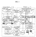
- Fig. 1 shows an example of the structure of a network in which existing telephone networks 13 (13a and 13b) and an IP network 14 is connected, to which the invention is applied.
- An intelligent network has the structure in which a service control point (SCP) 4 of the intelligent network and a plurality of switching systems 8 (8a, 8b, 8c) are connected via a No. 7 common channel signaling system (SS7) 18. To the switching systems 8, subscriber's terminals 9 (9a, 9b) are connected via subscriber's lines.
- SCP service control point
- SS7 common channel signaling system
- the IP network 14 such as Internet and the transport layer constructed by the plurality of switching systems 8 are connected to each other via gateways 2 (2a, 2b, 2c, 2d).
- a server 3b for controlling the bandwidth of a gateway and address information is connected to the gateways 2a and 2b and a server 3c is connected to the gateways 2c and 2d.
- a service control gateway 1a is connected to the IP network 14 and the SCP 4.
- Another service control gateway 1b connected to the IP network 14 is connected to another SCP existing in another intelligent network.
- the SS7 (18) is terminated by the gateway 2.
- the SS7 (18) may be terminated by the server 3b.
- a plurality of transit routers 7 (7a, 7b, 7c) and an interconnecting gateway router 6 are connected by using the internet protocol and form an IP core network 16.
- the IP network 14 is connected to another IP network via the interconnecting gateway router 6.
- An IP network 17 is connected to the transit router 7a via a gateway 5.
- Terminals 11 and 12 , a server 3a and gateway 5 are connected to the IP network 17. The bandwidth and addresses of the terminals 11 and 12 and gateway 5 are controlled by the server 3a.
- the servers 3 (3a, 3b, 3c) build a virtual IP control network 15.
- the service control gateway 1 transmits/receives a signal regarding services between the server 3 and the SCP 4 and performs translation between the IP protocol and the protocol used in the existing telephone network.
- the service control gateway 1 stores information for determining an SCP to be accessed and information used to authenticates the user on the basis of the information received by the server 3.
- the service control gateway 1 is connected to the IP network and the SS7 (18) and performs translation between the IP protocol and the SS7 protocol in Fig. 1, a configuration such that the service control gateway 1 is disposed between the IP network and the intelligent network and translation between the IP protocol and the protocol in the intelligent network is performed may be also used. It is also possible to employ a configuration such that the service control gateway 1 and the SCP 4 are integrally formed and the SCP 4 directly receives information from the server 3.
- the SCP 4 provides network-wide services such as number translating service represented by toll free service and customer services based on information registered for each user.
- the gateway 2 has the function of IP encapsulating voice to provide voice service also on the IP network, means for transferring signal information used by the SS7 (18), and means for carrying out communications with a device in the IP network 14 by the internet protocol.
- a VoIP gateway for providing internet telephone service run and managed by a communication enterprise is employed.
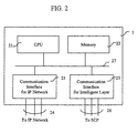
- Fig. 2 shows the structure of the service control gateway 1.
- the service control gateway 1 has the structure such that a CPU 21 for controlling a signal transmitted to/from the SCP and the gateways, a memory 22, a communication interface 23 for the IP network for terminating signal lines 24 extended from the IP network, and a communication interface 25 for the intelligent network for terminating signal lines 26 extended from the SCP are connected via a bus 27.
- a program for transmitting/receiving a signal to/from the server and the SCP, information necessary to access services realized by the SCP, and authentication information used to access the SCP are stored.
- the communication between the CPU 21 and the SCP is performed by, for example, newly creating a message used in the IN and using it.
- the communication between the CPU 21 and the server is performed by, for example, using the internet protocol.
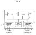
- Fig. 3 shows the structure of the gateway 2.
- the gateway 2 has the structure such that a CPU 31 for controlling a signal to/from an apparatus connected to the IP network and an apparatus connected to the transport layer, a memory 32, a communication interface 33 for the IP network for terminating signal lines 34 extended from the IP network, a communication interface 35 for the transport layer for terminating signal lines 36 extended from the transport layer, and a voice encapsulation unit 38 for encapsulating voice information are connected via a bus 37.
- the communication between the CPU 31 and an apparatus on the IP network is performed by, for example, using the internet protocol.
- the communication between the CPU 31 and the transport layer is carried out by, for example, using an ISDN user part protocol (ISUP) of N-ISDN.
- ISUP ISDN user part protocol
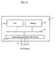
- Fig. 4 shows the structure of the server 3.
- the server 3 has the configuration such that a CPU 41 for controlling a signal to/from another apparatus connected to the IP network, a memory 42, and a communication interface 43 for the IP network for terminating signal lines 44 extended from the IP network are connected via a bus 45.
- the memory 42 stores therein correspondence information between telephone number and an IP address of each of the terminals and gateways controlled by the server 3, user authentication information, a program for performing authentication, information and a program for controlling the bandwidth, and information and a program necessary to transmit/receive signals to/from the server and router on the IP network 14.
- the communication between the CPU 41 and an apparatus on the IP network is performed by, for example, using the internet protocol.
- the server 3 terminates the SS7 (18) , the SS7 (18) interface is added to the server 3.
- a processing flow of the server 3 in the case where a call is generated from a subscriber's terminal connected to the IP network to a subscriber's terminal connected to the telephone network and that in the case of providing services of the SCP 4 to subscriber's terminals connected to the IP network will be described.
- a case in which a call is generated from the terminal 11 connected to the IP network 17 to the terminal 9a connected to the telephone network will be described as an example.
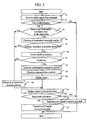
- Fig. 5 shows a processing flow executed by the CPU 41 of the server 3a.
- the processing flow is executed when a call is generated from a subscriber's terminal connected to the IP network to a subscriber's terminal connected to the telephone network.
- the server 3a receives an admission request signal (ARQ) from the terminal 11 (step 51). Upon detection of the signal, the server 3a transfers the signal to the memory 42 via the communication interface 45 for the IP network and starts a signal receiving process by using a program stored in the memory. The server 3a analyzes information elements included in the received signal and determines whether a call from the user can be accepted or not (52).
- ARQ admission request signal
- the server 3a compares the areas where the terminals exist (53). When the terminals exist in the same area, the server 3a retrieves the IP address of the destination terminal 9a and the information of a channel which performs a call process by using the information stored in the memory 42 (64). The server 3a which has detected the necessary information updates the status of the source terminal 11 from "idle" to "busy” (61). The server 3a determines the bandwidth allocated to the call (62), transmits an admission confirm (ACF) signal to the source terminal 11, and finishes the routine (63). When there is no bandwidth to be allocated in step 62, an error signal is transmitted to the source terminal 11 (65).
- ACF admission confirm
- the number of the destination terminal 9a is compared with the information stored in the memory 42 and the class of the destination terminal number is determined (54).
- the IP address of the gateway corresponding to the destination terminal number or the IP address of the server which manages the gateway and the information of the channel for the call process are retrieved (64). Subsequently, a call setup process is performed in a manner similar to the case where the source and destination terminals exist in the same area.
- a cache stored in the memory 42 is checked and whether or not an interrogation has been sent to other servers for the class number resolution within a predetermined period in the past (56).
- an interrogation has been sent to a server in the past predetermined period
- the IP address of the server which responded at that time and the information of the channel for performing the call process are retrieved (64).
- the number (telephone number information such as an address specified by E.164) for identifying the destination terminal is included in the request signal. It is assumed that information associating the telephone number with the IP address is provided for each server by either a method of periodically exchanging information among servers and storing the information or a method of entering the information by a network operator when the service is started. It is assumed that information of the server to which communication can be performed from the server 3a is preset in the memory 42 in each server by the network operator or each server is registered in an IP multicast address.
- Fig. 9 shows an example of an information table in the memory 42 in the server 3a.
- Destination number pattern 301 shows the pattern of destination number. This is compared with the destination terminal number received from the terminal and class 302 is determined.
- the IP address of the corresponding server or the gateway 2 is written in the IP address 303.
- a multicast address corresponding to the class is written.
- the address of the server 3 used at that time is written in a cache 304.
- the period of validity 305 the period of validity of the cache is written.
- the clock of the system shows time after the period of validity, the data in the cache is not used.
- Reference numerals 3011 to 3013 show examples of specific patterns. "?” denotes an arbitrary number from 0 to 9 and [1-8] denotes an arbitrary number from 1 to 8.
- 3011 shows an example of a pattern in which the address can be resolved inside.
- class 3021 is that "address resolution is possible at server 3a", so that the address of the server 3 or gateway 2 is written in the IP address 3031. Since the cache and the period of validity are not necessary, they are blank.
- 3012 and 3013 show examples of patterns in which the address cannot be resolved at the server. Since a plurality of cases such as 3022 and 3023 in which the address resolution is impossible at the server can be considered, it is necessary to cover all of patterns including the classes.
- IP addresses 3032 and 3033 multicast addresses corresponding to the classes are written.
- cashes 3042 and 3043 the address of the server 3 which can access the service control gateway 1 that corresponded in the past is written.
- validity periods 3052 and 3053 the period of validity of the cache is written.
- the server 3 when the server 3 that has received the multicasted interrogation request determines that the call can be processed by itself from the information included in the interrogation request signal, the server 3 transmits an answer message including the information of the channel in which the call process is performed to the server 3a (59).
- the answer message includes information (correlation ID) indicating that the message is an answer to the interrogation request.
- the server 3a which has received the answer message updates the cache (60) and updates the status of the source terminal 11 from "idle" to "busy” (61).
- the server 3a determines the bandwidth allocated to the call (62), transmits the admission confirm to the source terminal, and finishes the routine (63). When there is no bandwidth to be allocated, the server 3a transmits an error signal to the source terminal 11 (65).
- Fig. 6 shows a processing flow executed by the CPU 41 of the server 3b.
- the server 3b When a call to a number that requires multicasting of an interrogation request is made from a terminal under the control of the server 3a to the server 3a, the server 3b receives the interrogation request from the server 3a (71). Information of the server as the interrogation request transmission source, which is stored in the memory 42 of the server 3b and can be accessed and the number of servers which have sent the interrogation request within a predetermined period are read, and whether the interrogation request can be processed or not is checked (72). Then whether the service control gateway 1 corresponding to the interrogation signal can be accessed or not is determined (73). When it is accessible, a response signal to the interrogation signal is transmitted to the server 3a (74). The response signal includes information (correlation ID) indicative of a response to the interrogation signal.
- the server 3b starts a timer and waits for a call setup request signal from a terminal managed by the server 3a or the server 3a (75).
- a call processing signal is transmitted to the server 3a or the terminal controlled by the server 3a (77). Then it is determined from the destination number information that the service control gateway 1a has to be accessed, the address information is retrieved (78), and a service request signal is transmitted to the service control gateway 1a (79).
- the service control gateway 1a When the service request signal from the server 3b is received, the service control gateway 1a transmits the service request signal to the SCP 4. When a response signal to the service request signal is received from the SCP 4, the service control gateway 1a transmits a response signal to the service request from the server 3b to the server 3b (80).
- the response signal comprises number information including routing information to the destination terminal.
- the server 3b retrieves the address information of the gateway which performs an interwork with the telephone interwork (81).
- the server 3b transmits a call setup request to the gateway (82).
- the server 3b receives the admission request including correlating information between the call setup request and this admission request (correlation ID) from the gateway which has received the call setup request from the server 3b (83)
- the user authentication process is performed by using the information prestored in the memory 42 (84).
- the authentication result is OK
- the status of the terminal is updated from "idle” to "busy” (85) and the bandwidth is allocated to the call (86).
- an admission confirm (ACF) signal including the correlation ID is transmitted to the gateway (87) and the server 3b waits for a call processing signal from the gateway.
- the received signal is discarded (88) and the server returns to the idle state (89).
- the server When the call setup request signal including a proper correlation ID is not received from the server 3a or a terminal controlled by the server 3a within a predetermined period in step 75, the server returns to the idle state (89).
- step 84 When the user authentication process is failed in step 84 or when the bandwidth cannot be allocated in step 86, an error signal is transmitted to the gateway and the routine is finished (90).
- a method of transmitting a call from a terminal on an IP network to a terminal on a telephone network and a method of providing IN services on the telephone network to a terminal on an IP network will be described by using signal sequences shown in Figs. 7 and 8, respectively.
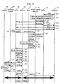
- Fig. 7 is a signal sequence diagram of a case where a call is transmitted from the terminal 11 having the telephone function connected to the IP network to the terminal 9b connected to the public telephone network. It is assumed that the protocol specified by ITU-T H.323 is used for the communication between a server existing on the IP network and the terminal, between the server and a gateway, and between the terminal and the gateway.
- the terminal 11 has registered for the server 3a for controlling the IP network 17 to which the terminal 11 belongs and obtained channel information (for example, port number of the TCP (transmission control protocol) or UDP (user datagram protocol)) used to exchange admission request or the like with the server 3a.
- channel information for example, port number of the TCP (transmission control protocol) or UDP (user datagram protocol) used to exchange admission request or the like with the server 3a.
- ARQ admission request
- the server 3a which has received the admission request reads a program for executing the above-mentioned processing flow of Fig. 5 from a memory and executes the program.
- an authentication process is performed by using the identifier of the source terminal included in the received signal.
- the identifier of the source terminal included in the received signal is compared with destination number information to check whether the call set between them is a call in the same area or not.
- the class of the destination number is checked by using the information prestored in the memory 42.
- the IP address of the server 3b controlling the gateway to which the destination terminal is connected is unconditionally determined from the destination number
- the IP address of the server 3b and the information (such as port number of the TCP) used to transmit/receive the call process signal information are retrieved (202).
- the server 3a updates the status of the source terminal, determines the bandwidth to be allocated to the call, and transmits an admission confirm (ACF) signal including the address information of the server 3b and the information of the bandwidth which can be used to the terminal 11 (203).
- ACF admission confirm
- the terminal 11 In order to transmit/receive the call process signal to/from the server 3b on the basis of the ACF, the terminal 11 sets up reliable connection such as TCP and then transmits a call setup request signal (Setup) to the server 3b (204). When the call is receivable, the server 3b which has received the signal transmits a call processing signal (Call Proc) to the terminal 11 (205).
- a call setup request signal Setup
- the server 3b which has received the signal transmits a call processing signal (Call Proc) to the terminal 11 (205).
- the server 3b determines the IP address of the gateway 2a nearest to the destination terminal and information (such as port number of TCP) used to transmit/receive the call process signal information by using the information in the memory 42 from the destination number information included in the received call setup request signal (206).
- information such as port number of TCP
- a reliable connection such as TCP is set up and a call setup request signal (Setup) is transmitted (207).
- the gateway 2a which has received the call setup request signal transmits an admission request (ARQ) to request the authentication process and the bandwidth allocation to the server 3b (208).
- ARQ admission request
- the server 3b performs the authentication process on the destination user, updates the status of the destination terminal from "idle” to "busy”, allocates a bandwidth to the call, and transmits an admission confirm (ACF) signal including the useable bandwidth information to the gateway 2a (209).
- ACF admission confirm
- the gateway 2a transmits a call processing signal (Cal Proc) to the server 3b (210) and transmits an initial address message (IAM) to the switching system 8b to which the destination terminal is connected by using the SS7 (18) (211).
- Cal Proc call processing signal
- IAM initial address message
- the switching system 8b which has received the message transmits a call setup request signal (Setup) to the terminal 9b (212).
- the call processing signal (Call Proc) is transmitted to the switching system 8b (213).
- the switching system 8b transmits an address complete message (ACM) to the gateway 2a (214).
- a connect signal (Connect) is transmitted from the terminal 9b to the switching system 8b (216).
- the switching system 8b transmits an answer message (ANM) to notify the gateway 2a that the destination user responded to the call (217).
- the gateway 2a transmits a connect signal (Connect) including transport address information (such as port number of the UDP) used to transfer voice information to the server 3b (218).
- the server 3b transmits the received connect signal (Connect) including the transport address information to the terminal 11 (219).
- voice can be transferred between the gateway 2a and the terminal 11 on the IP network by using, for example, the RTP (Real-Time Transport Protocol).
- a call can be made from a terminal as a subscriber of internet telephone on an IP network to a terminal on the telephone network.
- the call process can be performed without using the server 3b.
- the terminal 11 has registered in the server 3a for controlling the IP network 17 to which the terminal 11 belongs and obtained channel information (for example, port number of the TCP or UDP) used to exchange admission request and the like with the server 3a.
- channel information for example, port number of the TCP or UDP
- the terminal 11 When the terminal 11 generates a call, first, an admission request (ARQ) is sent to the server 3a by using the channel (251).
- the server 3a which has received the admission request reads a program for executing the processing flow of Fig. 5 from a memory and executes the program.
- an authentication process is performed by using the identifier of the source terminal included in the admission request from the server 3a.
- the identifier of the source terminal included in the received signal is compared with destination number information to check whether the call is made in the same area or not.
- the class of the destination number is checked by using the information prestored in the memory 42.
- the information in the cache in the memory of the server 3a is retrieved.
- an interrogation request is multicasted to a plurality of servers with the function of accessing the service control gateways 1 (1a, 1b) (252, 253).
- the server 3b (or 3c) which has received the interrogation request reads a program for executing the processing flow shown in Fig. 6 from the memory 42 and executes it.
- the process of authenticating the server which has sent multicasted interrogation request is performed.
- an answer message including address information such as port number of the TCP used to transmit/receive the call process signal of the server 3b to the server 3a (254) and the server 3b waits for a call setup request signal (Setup) from the terminal 11 or the server 3a.
- the server 3a updates the status of the terminal 11 from "idle” to "busy”, determines the bandwidth to be allocated to the call, and transmits admission confirm (ACF) including the address information used to transmit/receive the call process signal received from the server 3b to the terminal 11 (255).
- ACF admission confirm
- the terminal 11 In order to transmit/receive the call process signal to/from the server 3b on the basis of the received information, the terminal 11 sets up reliable connection such as the TCP and then transmits a call setup request signal (Setup) to the server 3b (256). When the call can be received, the server 3b which has received the signal transmits a call processing signal (Call Proc) to the terminal 11 (257).
- a call setup request signal Setup
- the server 3b which has received the signal transmits a call processing signal (Call Proc) to the terminal 11 (257).
- the server 3b determines that the call requires an access to the SCP by using the information in the memory from the destination number information included in the received call setup request signal (258), determines the IP address of the service control gateway 1a from the destination number, and transmits the service request signal to the service control gateway 1a (259).
- the service control gateway 1a After performing the server authentication process, when the SCP 4 can be accessed, the service control gateway 1a converts a low-order protocol so that the received signal can be transferred by the SS7 (18) and transmits the service request signal to the SCP 4 (261).
- the SCP 4 which has received the service request starts the IN service process program, translates logical number starting from, for example, 0120 to physical number to enable routing to the terminal corresponding to the logical number to be performed (262) , and transmits an answer message including the translated number to the server 3b via the service control gateway 1a (263, 264).
- the server 3b determines the IP address of the gateway 2a which is the closest to the number used for the routing in the telephone network included in the answer message 264 and information (such as port number of TCP) used to transmit/receive the call process signal information (265).
- information such as port number of TCP
- the subsequent processes are similar to those of step 207 and subsequent steps in Fig. 7.
- a reliable connection such as the TCP is set up and a call setup request signal (Setup) is transmitted (266).
- the gateway 2a which has received the call setup request signal transmits an admission request (ARQ) to request the authentication process and the bandwidth allocation to the server 3b (267).
- ARQ admission request
- the server 3b performs the authentication process on the terminal indicated by the routing number, updates the status of the destination terminal from "idle” to "busy”, allocates the bandwidth to the call, and transmits an admission confirm (ACF) signal including the useable bandwidth information to the gateway 2a (268).
- the gateway 2a transmits a call processing signal (Cal Proc) to the server 3b (269) and transmits an initial address message (IAM) to the switching system 8b to which the destination terminal is connected by using the SS7 (18) (270).
- Cal Proc call processing signal
- IAM initial address message
- the switching system 8b which has received the message transmits a call setup request signal (Setup) to the terminal 9b (271).
- the terminal transmits a call processing signal (Call Proc) to the switching system 8b (272).
- the switching system 8b transmits an address complete message (ACM) to the gateway 2a (273).
- a connect signal (Connect) is transmitted from the terminal 9b to the switching system 8b (275).
- the switching system 8b transmits an answer message (ANM) to the gateway 2a to notify that the destination user responded to the call (276).
- the gateway 2a transmits a connect signal (Connect) including transport address information (such as port number of the UDP) used to transfer voice information to the server 3b (277).
- the server 3b transmits a connect signal (Connect) including the transport address information in the received connect signal to the terminal 11 (278).
- voice can be transferred between the gateway 2a and the terminal 11 on the IP network by using, for example, the RTP (Real-Time Transport Protocol).
- services provided by using the IN can be used from a terminal as a subscriber of internet telephone on an IP network.
- Fig. 10 shows an example of the structure in which the existing telephone networks 13 (13a, 13b) and the IP network 14 are connected, to which the invention is applied.
- a difference from Fig. 1 is that the intelligent network and the service control gateway are omitted because they are not necessary to explain the method.
- the intelligent network may exist in practice.
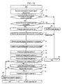
- Fig. 11 shows the processing flow executed by the CPU 41 of the server 3b.
- the difference from Fig. 6 is that no communication with the service control point via the service control gateway exists.
- the processing flow executed by the CPU 41 of the server 3a is basically unchanged.
- Fig. 12 shows a signal sequence used when a call is generated from the terminal 11 having the telephone function connected to the IP network to the terminal 9b connected to the public telephone network.
- the difference from Fig. 7 is that, since the destination number cannot be translated to the IP address of the server 3b (202) , an interrogation request is multicasted to servers which can resolve the IP address (301, 302) and the ACF 203 is transmitted from the server 3a to the terminal on the basis of the result.
- a call can be made from the terminal 11 also to telephone number which does not exist in the IP address - telephone number correspondence information in the server 3a.
- the telephone service realized by the linkage of the IP network such as Internet and the public network
- services provided by a service control point of an intelligent network can be efficiently used and the number of kinds of telephone services realized by the linkage of the IP network and the public telephone network can be increased.
- a communication enterprise having the service control point can enlarge the service usable range.
Applications Claiming Priority (2)
| Application Number | Priority Date | Filing Date | Title |
|---|---|---|---|
| JP9126799 | 1999-03-31 | ||
| JP9126799A JP3633356B2 (ja) | 1999-03-31 | 1999-03-31 | サーバ装置、サービス制御ゲートウェイ装置、サービス制御装置及び通信制御方法 |
Publications (2)
| Publication Number | Publication Date |
|---|---|
| EP1051046A2 true EP1051046A2 (fr) | 2000-11-08 |
| EP1051046A3 EP1051046A3 (fr) | 2001-06-27 |
Family
ID=14021671
Family Applications (1)
| Application Number | Title | Priority Date | Filing Date |
|---|---|---|---|
| EP20000101611 Withdrawn EP1051046A3 (fr) | 1999-03-31 | 2000-01-28 | Procédé pour fournir des services de réseau intelligent dans un réseau IP |
Country Status (3)
| Country | Link |
|---|---|
| US (1) | US6829232B1 (fr) |
| EP (1) | EP1051046A3 (fr) |
| JP (1) | JP3633356B2 (fr) |
Cited By (1)
| Publication number | Priority date | Publication date | Assignee | Title |
|---|---|---|---|---|
| WO2006050668A1 (fr) | 2004-11-15 | 2006-05-18 | Huawei Technologies Co., Ltd | Un procede pour appeler le service dans le reseau intelligent |
Families Citing this family (37)
| Publication number | Priority date | Publication date | Assignee | Title |
|---|---|---|---|---|
| WO2000070883A1 (fr) * | 1999-05-14 | 2000-11-23 | Nokia Networks Oy | Passerelle telephonique ip |
| US7388953B2 (en) * | 1999-09-24 | 2008-06-17 | Verizon Business Global Llc | Method and system for providing intelligent network control services in IP telephony |
| US6636596B1 (en) * | 1999-09-24 | 2003-10-21 | Worldcom, Inc. | Method of and system for providing intelligent network control services in IP telephony |
| GB2355362B (en) * | 1999-10-12 | 2003-08-06 | Ericsson Telefon Ab L M | Media gateway control |
| US6907032B2 (en) * | 2000-03-06 | 2005-06-14 | Goremote Internet Communications, Inc. | Method for selecting terminating gateways for an internet telephone call using a tree search |
| US7991697B2 (en) * | 2002-12-16 | 2011-08-02 | Irdeto Usa, Inc. | Method and system to digitally sign and deliver content in a geographically controlled manner via a network |
| US7389531B2 (en) * | 2000-06-16 | 2008-06-17 | Entriq Inc. | Method and system to dynamically present a payment gateway for content distributed via a network |
| US7404084B2 (en) | 2000-06-16 | 2008-07-22 | Entriq Inc. | Method and system to digitally sign and deliver content in a geographically controlled manner via a network |
| US6961858B2 (en) * | 2000-06-16 | 2005-11-01 | Entriq, Inc. | Method and system to secure content for distribution via a network |
| US7237255B2 (en) * | 2000-06-16 | 2007-06-26 | Entriq Inc. | Method and system to dynamically present a payment gateway for content distributed via a network |
| EP1202520A1 (fr) * | 2000-10-23 | 2002-05-02 | THOMSON multimedia | Procédé et dispositif de transmission de données dans un système de télévision |
| JP4212230B2 (ja) * | 2000-10-31 | 2009-01-21 | 富士通株式会社 | メディア通信システム及び該システムにおける端末装置 |
| EP1207667B1 (fr) * | 2000-11-17 | 2006-03-22 | Siemens Aktiengesellschaft | Procédé et système de communication pour l'établissement d'une liaison H.323 ou SIP à partir d'un réseau source vers une destination externe |
| JP2002290551A (ja) | 2001-03-28 | 2002-10-04 | Nec Corp | ゲートウェイシステム及びそれに用いる障害処理方法 |
| JP2002354122A (ja) * | 2001-05-25 | 2002-12-06 | Fujitsu Ltd | サービス提供システム |
| JP2003078572A (ja) | 2001-09-04 | 2003-03-14 | Nec Corp | 音声ゲートウエイ装置 |
| JP2003110609A (ja) * | 2001-09-28 | 2003-04-11 | Fujitsu Ltd | 通信装置 |
| JP4517567B2 (ja) * | 2001-11-12 | 2010-08-04 | 株式会社日立製作所 | 交換装置 |
| JP3746713B2 (ja) * | 2001-12-28 | 2006-02-15 | 株式会社日立製作所 | インターネット電話システムおよび情報処理装置 |
| KR100871118B1 (ko) * | 2002-05-18 | 2008-11-28 | 엘지전자 주식회사 | 멀티캐스트 그룹 관리 방법 |
| KR100898250B1 (ko) | 2003-01-24 | 2009-05-18 | 주식회사 케이티 | Megaco 기반 액세스 게이트웨이의 전화가입자에대한 지능망 서비스 제공시스템 및 방법 |
| US7564836B2 (en) * | 2003-03-27 | 2009-07-21 | Panasonic Corporation | Internet telephone apparatus, adapter and server for internet telephone communication, internet telephone system, and control method |
| JP4253569B2 (ja) * | 2003-12-03 | 2009-04-15 | 株式会社日立コミュニケーションテクノロジー | 接続制御システム、接続制御装置、及び接続管理装置 |
| JP2005318121A (ja) * | 2004-04-27 | 2005-11-10 | Ntt Docomo Inc | セッション管理装置 |
| US20070198837A1 (en) * | 2005-04-29 | 2007-08-23 | Nokia Corporation | Establishment of a secure communication |
| TWI295432B (en) | 2005-12-22 | 2008-04-01 | Ind Tech Res Inst | Method and system for converting service type of device connected to control gateway |
| EP1977579A1 (fr) * | 2005-12-27 | 2008-10-08 | TELEFONAKTIEBOLAGET LM ERICSSON (publ) | Procédé et système destinés à faciliter l'établissement d'une liaison ip dans un système de télécommunication |
| JP2007221481A (ja) * | 2006-02-16 | 2007-08-30 | Toshiba Corp | 電話システム |
| US8477918B2 (en) * | 2007-07-26 | 2013-07-02 | Nec Corporation | Multimedia providing service |
| US20100185734A1 (en) * | 2009-01-19 | 2010-07-22 | Moxa Inc. | Method for processing response messages |
| WO2012162888A1 (fr) * | 2011-06-01 | 2012-12-06 | 宇龙计算机通信科技(深圳)有限公司 | Procédé et dispositifs pour mettre en œuvre une communication entre des terminaux |
| JP5828071B2 (ja) * | 2011-08-24 | 2015-12-02 | パナソニックIpマネジメント株式会社 | 一斉通信システム、呼制御サーバ、および通信方法 |
| TWI499245B (zh) * | 2012-08-17 | 2015-09-01 | Hon Hai Prec Ind Co Ltd | 閘道器及利用其建立網路語音通訊的方法 |
| US10039113B2 (en) | 2016-03-28 | 2018-07-31 | Bank Of America Corporation | Intelligent resource procurement system based on physical proximity to related resources |
| US10796253B2 (en) | 2016-06-17 | 2020-10-06 | Bank Of America Corporation | System for resource use allocation and distribution |
| US10334462B2 (en) * | 2016-06-23 | 2019-06-25 | Bank Of America Corporation | Predictive analytics for resource development based on information communicated from inter-related communication devices |
| US10439913B2 (en) | 2016-07-01 | 2019-10-08 | Bank Of America Corporation | Dynamic replacement and upgrade of existing resources based on resource utilization |
Citations (2)
| Publication number | Priority date | Publication date | Assignee | Title |
|---|---|---|---|---|
| WO1996038018A1 (fr) * | 1995-05-24 | 1996-11-28 | Telefonaktiebolaget Lm Ericsson (Publ) | Procede et systeme d'etablissement d'une communication telephonique dans differents reseaux |
| JPH1168851A (ja) * | 1997-08-12 | 1999-03-09 | Kokusai Denshin Denwa Co Ltd <Kdd> | 回線交換網とインターネット網との網間経路制御通信システム |
Family Cites Families (8)
| Publication number | Priority date | Publication date | Assignee | Title |
|---|---|---|---|---|
| US5737333A (en) * | 1995-06-23 | 1998-04-07 | Lucent Technologies Inc. | Method and apparatus for interconnecting ATM-attached hosts with telephone-network attached hosts |
| GB9603582D0 (en) * | 1996-02-20 | 1996-04-17 | Hewlett Packard Co | Method of accessing service resource items that are for use in a telecommunications system |
| JP3455032B2 (ja) * | 1996-10-31 | 2003-10-06 | 株式会社日立製作所 | 通信システム |
| US6195425B1 (en) * | 1996-11-21 | 2001-02-27 | Bell Atlantic Network Services, Inc. | Telecommunications system with wide area internetwork control |
| US6683870B1 (en) * | 1997-02-10 | 2004-01-27 | Mci Communications Corporation | Method and system for multicasting call notifications |
| US6215790B1 (en) * | 1997-03-06 | 2001-04-10 | Bell Atlantic Network Services, Inc. | Automatic called party locator over internet with provisioning |
| US6233234B1 (en) * | 1997-06-03 | 2001-05-15 | Bell Atlantic Network Services, Inc. | Secure LAN/internet telephony |
| JPH1168861A (ja) | 1997-08-11 | 1999-03-09 | Hitachi Ltd | 同時双方向送受信方法および同時双方向送受信回路 |
-
1999
- 1999-03-31 JP JP9126799A patent/JP3633356B2/ja not_active Expired - Fee Related
-
2000
- 2000-01-28 EP EP20000101611 patent/EP1051046A3/fr not_active Withdrawn
- 2000-01-28 US US09/493,796 patent/US6829232B1/en not_active Expired - Fee Related
Patent Citations (2)
| Publication number | Priority date | Publication date | Assignee | Title |
|---|---|---|---|---|
| WO1996038018A1 (fr) * | 1995-05-24 | 1996-11-28 | Telefonaktiebolaget Lm Ericsson (Publ) | Procede et systeme d'etablissement d'une communication telephonique dans differents reseaux |
| JPH1168851A (ja) * | 1997-08-12 | 1999-03-09 | Kokusai Denshin Denwa Co Ltd <Kdd> | 回線交換網とインターネット網との網間経路制御通信システム |
Non-Patent Citations (2)
| Title |
|---|
| PATENT ABSTRACTS OF JAPAN vol. 1999, no. 08, 30 June 1999 (1999-06-30) & JP 11 068851 A (KOKUSAI DENSHIN DENWA CO LTD), 9 March 1999 (1999-03-09) * |
| SENGODAN S: "A GATEKEEPER DISCOVERY MECHANISM FOR H.323 SYSTEMS" SPIE CONFERENCE ON MULTIMEDIA SYSTEMS AND APPLICATIONS, BOSTON, MA, USA, November 1998 (1998-11), XP000893007 * |
Cited By (4)
| Publication number | Priority date | Publication date | Assignee | Title |
|---|---|---|---|---|
| WO2006050668A1 (fr) | 2004-11-15 | 2006-05-18 | Huawei Technologies Co., Ltd | Un procede pour appeler le service dans le reseau intelligent |
| EP1816797A1 (fr) * | 2004-11-15 | 2007-08-08 | Huawei Technologies Co., Ltd. | Un procede pour appeler le service dans le reseau intelligent |
| EP1816797A4 (fr) * | 2004-11-15 | 2008-03-19 | Huawei Tech Co Ltd | Un procede pour appeler le service dans le reseau intelligent |
| US7627107B2 (en) | 2004-11-15 | 2009-12-01 | Huawei Technologies, Co., Limited | Method and system for invoking the service in the intelligent network |
Also Published As
| Publication number | Publication date |
|---|---|
| EP1051046A3 (fr) | 2001-06-27 |
| US6829232B1 (en) | 2004-12-07 |
| JP2000286897A (ja) | 2000-10-13 |
| JP3633356B2 (ja) | 2005-03-30 |
Similar Documents
| Publication | Publication Date | Title |
|---|---|---|
| US6829232B1 (en) | Communication method for terminals connected to IP networks to receive services provided by intelligent networks | |
| US7187671B2 (en) | Circuit switched private communication network with integrated packet switched multimedia extensions | |
| US6876632B1 (en) | Intelligent network with an internet call waiting function | |
| JP3880867B2 (ja) | Ipエンドポイント間のipベアラパスを管理するためのipパケットアクセスゲートウェイ(ippag)システムおよび方法およびコンピュータプログラム製品 | |
| US6807166B1 (en) | Gateway for internet telephone | |
| JP3753316B2 (ja) | 呼詳細記録の生成方法 | |
| JPH0685907A (ja) | 呼ルーティング方法および装置 | |
| WO2006108168A2 (fr) | Systemes et procedes permettant l'interfonctionnement de signalisations qsig et h.323 dans un reseau sip | |
| JPH10303990A (ja) | オーディオ接続を確立する方法および分散型データベース | |
| KR20020059733A (ko) | 음성 데이터 통합 전화통신 게이트웨이를 위한 장치 및이를 사용하기 위한 방법 | |
| JPH0685925A (ja) | 通信交換システムおよびその制御方法 | |
| US7369539B1 (en) | System and method for providing service control to a single telephone end terminal from multiple service providers | |
| JPH07250153A (ja) | ダイヤル方式管理方法および装置 | |
| EP1081920B1 (fr) | Procédé d' établissement d' une session de communication entre un terminal d' un réseau à commutation de paquets et un terminal connecté à un serveur d' accès à distance | |
| US6493339B1 (en) | Method of handling a telephone call | |
| AU761977B2 (en) | Security in telecommunications network gateways | |
| US7221683B2 (en) | Telecommunications system having a packet-switching communications network and method for operating such a telecommunications system | |
| KR100406571B1 (ko) | 평생번호를 이용한 지능형 단말의 인터넷폰 수신 방법 및 그 시스템 | |
| KR100415117B1 (ko) | 인터넷프로토콜 전화시스템에서 인터넷프로토콜단말기들간의 다중통화 시 강제 착신장치 및 방법 | |
| Cisco | Cisco High-Performance Gatekeeper | |
| JP3710484B2 (ja) | 広帯域シグナリング | |
| KR100407810B1 (ko) | 음성 데이터 통합 인터넷 프로토콜과 공중전화 교환망간의 상호 지능망 서비스 방법 및 장치 | |
| US7512119B2 (en) | Method for establishing communication paths between access points of a communication system and a communication system using said method | |
| EP0998109B1 (fr) | Réseau de communications utilisant de serveurs autonomes pour l'établissment d' une session de communication | |
| CA2403629C (fr) | Procede et systeme d'etablissement de communication entre une premiere et une seconde entite de communication |
Legal Events
| Date | Code | Title | Description |
|---|---|---|---|
| PUAI | Public reference made under article 153(3) epc to a published international application that has entered the european phase |
Free format text: ORIGINAL CODE: 0009012 |
|
| AK | Designated contracting states |
Kind code of ref document: A2 Designated state(s): AT BE CH CY DE DK ES FI FR GB GR IE IT LI LU MC NL PT SE Kind code of ref document: A2 Designated state(s): DE FR GB |
|
| AX | Request for extension of the european patent |
Free format text: AL;LT;LV;MK;RO;SI |
|
| PUAL | Search report despatched |
Free format text: ORIGINAL CODE: 0009013 |
|
| AK | Designated contracting states |
Kind code of ref document: A3 Designated state(s): AT BE CH CY DE DK ES FI FR GB GR IE IT LI LU MC NL PT SE |
|
| AX | Request for extension of the european patent |
Free format text: AL;LT;LV;MK;RO;SI |
|
| 17P | Request for examination filed |
Effective date: 20011026 |
|
| AKX | Designation fees paid |
Free format text: DE FR GB |
|
| STAA | Information on the status of an ep patent application or granted ep patent |
Free format text: STATUS: THE APPLICATION IS DEEMED TO BE WITHDRAWN |
|
| 18D | Application deemed to be withdrawn |
Effective date: 20030801 |