EP1051030A2 - Videomischer mit Zwischenblendsignalsteuerung - Google Patents
Videomischer mit Zwischenblendsignalsteuerung Download PDFInfo
- Publication number
- EP1051030A2 EP1051030A2 EP00201520A EP00201520A EP1051030A2 EP 1051030 A2 EP1051030 A2 EP 1051030A2 EP 00201520 A EP00201520 A EP 00201520A EP 00201520 A EP00201520 A EP 00201520A EP 1051030 A2 EP1051030 A2 EP 1051030A2
- Authority
- EP
- European Patent Office
- Prior art keywords
- signal
- control
- fade
- video signal
- video
- Prior art date
- Legal status (The legal status is an assumption and is not a legal conclusion. Google has not performed a legal analysis and makes no representation as to the accuracy of the status listed.)
- Ceased
Links
Images

Classifications
-
- H—ELECTRICITY
- H04—ELECTRIC COMMUNICATION TECHNIQUE
- H04N—PICTORIAL COMMUNICATION, e.g. TELEVISION
- H04N5/00—Details of television systems
- H04N5/222—Studio circuitry; Studio devices; Studio equipment
- H04N5/262—Studio circuits, e.g. for mixing, switching-over, change of character of image, other special effects ; Cameras specially adapted for the electronic generation of special effects
- H04N5/265—Mixing
Definitions
- the invention relates to a mixing device for video signals according to the preamble of Claim 1.
- the invention also relates to the method for such a mixing device.
- mixing devices for video signals so-called video mixer, used to video signals from various sources, e.g. B. from Cameras, film scanners and recording devices, according to design requirements to combine with each other.
- Video mixer used to video signals from various sources, e.g. B. from Cameras, film scanners and recording devices, according to design requirements to combine with each other.
- Mixing device for example, a crossbar, with their help two sources to be combined in one processing stage can be selected.
- the picture contents of the two preselected video signals are in the processing stage superimposed, the proportion of the image content of the two video signals in the output signal can be controlled.
- a control device to achieve different Effects such as soft fade out, fade in, fade, cut fade, Trick blend or chroma key blend required for this Control signals generated.
- a video effect generator for example, is known from US Pat. No. 5,109,280 two input signals in an electronic mixing device by means of a signal generator be mixed.
- one of the inputs can also have a background generator which are a color signal with adjustable chrominance and Luminance creates.
- the object of the present invention is the creative possibilities of image mixing to increase, the operating effort should be kept as low as possible.
- the invention has the advantage that when fading from a first to one second video signal, a transition via a third signal - which in the following as Intermediate blend signal is called - can be achieved.
- a transition via a third signal - which in the following as Intermediate blend signal is called - can be achieved.
- the intermediate fade signal can be any selectable video source or can also be a synthetic image signal with freely selectable chrominance and luminance.
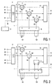
- a mixing unit is used 1 of three signal control means 11, 12, 13, a signal combiner 14 and a control device 15 formed.
- a cross bar 2 can at the inputs 21-25 Crossbar 2 connected video sources a first, second and a third input signal A, B, C can be selected for mixing unit 1.
- the selected input signals A, B, C are respective inputs 111, 121, 131 of the signal control means 11, 12, 13 fed.
- a digital mixer in which the input signals in digital Form, the signal control means 11, 12, 13 are formed from multipliers, in which the respective input signal A, B, C with one at the respective control input 112, 122, 132 applied control value x, y, z is multiplied.
- the signal control means for example, from voltage controllable Damping levels should be formed.
- the outputs 113, 123, 133 of the signal control means 11, 12, 13 are in the signal combiner 14 superimposed according to standards, so that, for example, if all input signals are black Image contents also have an output signal at the output 10 of the mixing unit 1 results in black image content.
- the fade process is from a Operator made by operating an operating element.
- Blend lever 151 for example, the control device 15 generates control values x, y for first and second input signals A, B which are proportional or inversely proportional to Adjustment state of the lever 151 are.
- an automatic crossfade process is triggered the control device 15, on the other hand, generates this by means of an operating button 152 Adjustment values automatically, whereby the duration of the crossfading process by other, not shown setting elements can be specified.
- the control device generates the control values required for the preselected transition x, y, z for the signal control means 11, 12, 13 and places them at outputs 151, 152, 153 available.
- a V fade from the first input signal A to second input signal B of the mixing unit 1 is first the manipulated variable x for the first Signal control means 11 withdrawn.
- the time course of the first manipulated variable x is in Figure 3a shown.
- the control device 15 increases the second manipulated variable y for the second signal control means 12 sliding to its maximum value (shown in Figure 3b). This will second input signal B faded in.
- the control device 15 generates a third manipulated variable z for the third Input signal C of the mixing unit 1. Withdrawn to the same extent as the first manipulated variable x becomes, the control device 15 increases the third manipulated variable z for the third Input signal C, which in the following due to its use as an intermediate blend signal is designated.
- Figure 3c shows the resultant time course of the third manipulated variable z. This way, when fading from first input signal A to the second input signal B, the intermediate blend signal C automatically shown and hidden.
- the roof-shaped signal curve of the third control signal z for the intermediate blend signal C is only intended as an example and should not be understood as a limitation of the invention to this signal curve.
- the person skilled in the art presents no problems in generating any signal curves for the third manipulated variable z in order to provide whatever artistic effect is desired.
- the control device 15 is preferably designed in such a way that a standardized video output signal is also obtained at the output of the mixing stage at all times when video signals conform to the standards at the inputs of the mixing stage.
- the value range of the manipulated values depends on the internally used signal display and resolution.
- the black value is equal to the binary value
- the monitoring of a standard-compliant video signal can be implemented in a simple manner by limiting the manipulated variable z for the intermediate fade signal to a value, if necessary, by adding the sum at any time of the fade x + y + z of the three manipulated values x, y, z is not greater than the manipulated value which, in the case of a fully modulated standard video signal at one of the inputs of the mixing device 1 (all other inputs show a black image), also produces a fully modulated standard video image at the output 10 of the mixing device 1. This reliably prevents overdriving during the crossfading process.
- a color generator 3 can also be provided as the signal source for the intermediate blend signal be which is connected to an input 25 of the crossbar 2 and which optionally instead of another video source can be selected as a fade-in signal.
- FIG. 2 shows another embodiment - in which the same for the same components Reference symbols as in FIG. 1 are used - in which such a color generator 3 is directly connected to the signal combiner 14.
- the third control signal z of the control circuit In this exemplary embodiment, 14 is connected directly to a control input L of the Color generator 3 connected to the in a correspondingly designed color generator 3 To control the luminance of the color generator 3.
- the result in both exemplary embodiments by generating a further control signal w by the control device 14 still other signal parameters of the intermediate blend signal, for example its Control chrominance during a crossfade.
- This is shown in FIG. 2 using the example of driving the color generator 3 with a chrominance control input C.
- a fourth control signal but also the control inputs of other interposed or upstream internal ones Signal processing stages are supplied. In this way, they multiply artistic design options.
- Another control option is provided by leading out the third control signal or a similar control signal v via an interface 16 for control external devices.
- a sound mixing device for example, can also be used as such an external device be connected to the interface 16. This can be done simultaneously with the fade-in and fade-out of the intermediate blend signal, a sound signal, for example Applause sounds can be added automatically.
- the invention is not based on conventional mixing devices constructed from dedicated hardware limited to video signals. It also includes mixing devices based on computer programs in which digitized video signals by means of appropriate Algorithms are mixed together.
- the manipulated values (v, w, x, y, z) correspond to in in this case variables or parameter values of the computer program.
Landscapes
- Engineering & Computer Science (AREA)
- Multimedia (AREA)
- Signal Processing (AREA)
- Studio Circuits (AREA)
Abstract
Description
- Fig. 1
- Schaltungsanordnung für eine erfindungsgemäße Mischvorrichtung,
- Fig. 2
- Alternative Schaltungsanordnung,
- Fig. 3
- Zeitdiagramm für erfindungsgemäßen Mischvorgang.
Vorzugsweise ist die Steuervorrichtung 15 hierbei so ausgebildet, dass bei normgerechten Videosignalen an den Eingängen der Mischstufe zu jedem Zeitpunkt auch ein normgerechtes Videoausgangssignal am Ausgang der Mischstufe erhalten wird. Der Wertebereich der Stellwerte ist von der intern verwendeten Signaldarstellung und Auflösung abhängig. Bei der konkreten Ausgestaltung des Ausführungsbeispiels ist der Schwarzwert gleich dem Binärwert

Claims (6)
- Vorrichtung zum Mischen von einem ersten und einem zweiten Videosignal (111, 121), wobei der Bildanteil des ersten und des zweiten Videosignals (111, 121) von einer Steuervorrichtung (15) vorgebbar ist und bei dem zum Erzielen einer Überblendung der Bildanteil des einen Videosignals (111) von der Steuervorrichtung (15) verringert und der Bildanteil des zweiten Videosignals erhöht wird,
dadurch gekennzeichnet,
dass die Steuervorrichtung (15) dazu vorgesehen ist, während einer Überblendung den Bildanteil wenigstens eines dritten Videosignals (131) zu steuern. - Mischvorrichtung nach Anspruch 1,
dadurch gekennzeichnet,
dass die Steuervorrichtung (15) zur Abgabe eines weiteren Steuersignals (v, w) während einer Überblendung vorgesehen ist. - Mischvorrichtung nach Anspruch 2,
dadurch gekennzeichnet,
dass die Mischvorrichtung eine Schnittstelle (16) für ein solches weiteres Steuersignal (v) aufweist. - Verfahren zum Mischen von einem ersten und einem zweiten Videosignal (111, 121), wobei der Bildanteil des ersten und des zweiten Videosignals (111, 121) vorgegeben werden kann und bei dem zum Erzielen einer Überblendung der Bildanteil des einen Videosignals (111) verringert und der Bildanteil des zweiten Videosignals erhöht wird,
dadurch gekennzeichnet,
dass während einer Überblendung der Bildanteil wenigstens eines dritten Videosignals gesteuert wird. - Verfahren nach Anspruch 4,
dadurch gekennzeichnet,
dass mittels eines weiteren Steuersignals (v, w) während einer Überblendung wenigstens eine weiteren Signalverarbeitungsparameter gesteuert wird. - Mischvorrichtung nach Anspruch 3,
dadurch gekennzeichnet,
dass ein an einer Mischvorrichtung extern angeschlossenes Gerät gesteuert wird.
Applications Claiming Priority (2)
| Application Number | Priority Date | Filing Date | Title |
|---|---|---|---|
| DE19920089 | 1999-05-03 | ||
| DE1999120089 DE19920089A1 (de) | 1999-05-03 | 1999-05-03 | Videomischer mit Zwischenblendsignalsteuerung |
Publications (2)
| Publication Number | Publication Date |
|---|---|
| EP1051030A2 true EP1051030A2 (de) | 2000-11-08 |
| EP1051030A3 EP1051030A3 (de) | 2002-03-20 |
Family
ID=7906669
Family Applications (1)
| Application Number | Title | Priority Date | Filing Date |
|---|---|---|---|
| EP00201520A Ceased EP1051030A3 (de) | 1999-05-03 | 2000-04-25 | Videomischer mit Zwischenblendsignalsteuerung |
Country Status (3)
| Country | Link |
|---|---|
| EP (1) | EP1051030A3 (de) |
| JP (1) | JP4554757B2 (de) |
| DE (1) | DE19920089A1 (de) |
Families Citing this family (1)
| Publication number | Priority date | Publication date | Assignee | Title |
|---|---|---|---|---|
| DE102014220423A1 (de) * | 2014-10-08 | 2016-04-14 | Fraunhofer-Gesellschaft zur Förderung der angewandten Forschung e.V. | Vorrichtung zum Erzeugen eines Videoausgangsdatenstroms, Videoquelle, Videosystem und Verfahren zum Erzeugen eines Videoausgangsdatenstroms bzw. eines Videoquellendatenstroms |
Family Cites Families (4)
| Publication number | Priority date | Publication date | Assignee | Title |
|---|---|---|---|---|
| US4205346A (en) * | 1978-06-09 | 1980-05-27 | Ross Video Limited | Video transition circuitry including transition previewing means |
| JPS63133382A (ja) * | 1986-11-24 | 1988-06-06 | Mitsubishi Electric Corp | Pcm緑音再生機 |
| JPH04129481A (ja) * | 1990-09-20 | 1992-04-30 | Sony Corp | 特殊効果映像作成方法 |
| DE19813076B4 (de) * | 1997-04-01 | 2004-05-06 | Bts Holding International Bv | Videomischer mit Maschinenkontrolle |
-
1999
- 1999-05-03 DE DE1999120089 patent/DE19920089A1/de not_active Withdrawn
-
2000
- 2000-04-25 EP EP00201520A patent/EP1051030A3/de not_active Ceased
- 2000-05-01 JP JP2000132092A patent/JP4554757B2/ja not_active Expired - Fee Related
Also Published As
| Publication number | Publication date |
|---|---|
| DE19920089A1 (de) | 2000-11-09 |
| EP1051030A3 (de) | 2002-03-20 |
| JP4554757B2 (ja) | 2010-09-29 |
| JP2000350092A (ja) | 2000-12-15 |
Similar Documents
| Publication | Publication Date | Title |
|---|---|---|
| DE68911563T2 (de) | Videoschalter mit unabhängiger Verarbeitung ausgewählter Videosignale. | |
| DE3838000C2 (de) | Videoproduktionseinrichtung | |
| DE3432122A1 (de) | Schaltungsanordnung zur bildung der groesse der vektorsumme zweier orthogonaler signale, beispielsweise zur verwendung in einem digitalen fernsehempfaenger | |
| DE2708778C3 (de) | Verfahren und Vorrichtung zum Farbstanzen von Farbvideosignalen in Abhängigkeit von der wählbaren Farbart eines Farbsignals | |
| DE68910255T2 (de) | Videoluminanz-Tastschaltung mit Eigentastung. | |
| DE4106306A1 (de) | Verfahren zur farbkorrektur eines videosignals | |
| DE3842977C2 (de) | Mischeinrichtung für Videosignale | |
| DE3444770A1 (de) | Elektronischer lautstaerkeregelkreis | |
| EP0758514A1 (de) | Verfahren zur farbtransformation und ein farbvideosystem | |
| DE2207536B2 (de) | Kontrastkompressionsschaltung für ein Farbfernsehaufnahmesystem mit mehreren Bildaufnahmeröhren | |
| DE3842978C2 (de) | Mischeinrichtung für Videosignale | |
| DE3943307A1 (de) | Verfahren und schaltungsanordnung zur aufbereitung von farbsignalen | |
| DE68915913T2 (de) | Digitalgerät für Videoeffekte. | |
| DE4444304C2 (de) | Verfahren zum Erzeugen eines zusammengesetzten Videobildes | |
| DE3238696C2 (de) | Generator zur Bildung von Schaltsignalen zum Farbstanzen von Farbvideosignalen | |
| DE4432788B4 (de) | Verfahren und Schaltung zur Erzeugung eines zusammengesetzten Videosignals | |
| DE69124825T2 (de) | Tastschaltung mit verstellbarer Formgebung | |
| DE19920089A1 (de) | Videomischer mit Zwischenblendsignalsteuerung | |
| DE4114440A1 (de) | Einrichtung zum mischen von videosignalen | |
| DE69015116T2 (de) | Verbesserte Tastschaltung mit Hervorhebung des Ausfüllen-Videosignals. | |
| DE3326272C1 (de) | Verfahren und Schaltungsanordnung zur Verbesserung der Qualitaet eines Fernsehbildes | |
| DE69517144T2 (de) | Verfahren und Vorrichtung zur Bildverbesserung | |
| DE3932758C2 (de) | Verfahren und Anordnung zur automatischen Einstellung von Stellgrößen bei der Ableitung eines Stanzsignals aus Videosignalen | |
| EP0019735A1 (de) | Verfahren und Schaltung zur Kontrastkorrektur von Farbfernsehsignalen | |
| DE3920456A1 (de) | Anordnung zur erzeugung von bildeffekten in videogeraeten |
Legal Events
| Date | Code | Title | Description |
|---|---|---|---|
| PUAI | Public reference made under article 153(3) epc to a published international application that has entered the european phase |
Free format text: ORIGINAL CODE: 0009012 |
|
| AK | Designated contracting states |
Kind code of ref document: A2 Designated state(s): AT BE CH CY DE DK ES FI FR GB GR IE IT LI LU MC NL PT SE Kind code of ref document: A2 Designated state(s): DE FR GB |
|
| AX | Request for extension of the european patent |
Free format text: AL;LT;LV;MK;RO;SI |
|
| PUAL | Search report despatched |
Free format text: ORIGINAL CODE: 0009013 |
|
| AK | Designated contracting states |
Kind code of ref document: A3 Designated state(s): AT BE CH CY DE DK ES FI FR GB GR IE IT LI LU MC NL PT SE |
|
| AX | Request for extension of the european patent |
Free format text: AL;LT;LV;MK;RO;SI |
|
| RAP1 | Party data changed (applicant data changed or rights of an application transferred) |
Owner name: BTS HOLDING INTERNATIONAL B.V. |
|
| 17P | Request for examination filed |
Effective date: 20020805 |
|
| AKX | Designation fees paid |
Free format text: DE FR GB |
|
| 17Q | First examination report despatched |
Effective date: 20061207 |
|
| RAP1 | Party data changed (applicant data changed or rights of an application transferred) |
Owner name: THOMSON LICENSING S.A. |
|
| RAP1 | Party data changed (applicant data changed or rights of an application transferred) |
Owner name: THOMSON LICENSING SA |
|
| STAA | Information on the status of an ep patent application or granted ep patent |
Free format text: STATUS: THE APPLICATION HAS BEEN REFUSED |
|
| 18R | Application refused |
Effective date: 20111026 |