EP1048542A2 - Verfahren und Vorrichtung zur Erhöhung der Normalkraft eines Schienenfahrzeugs - Google Patents
Verfahren und Vorrichtung zur Erhöhung der Normalkraft eines Schienenfahrzeugs Download PDFInfo
- Publication number
- EP1048542A2 EP1048542A2 EP00108466A EP00108466A EP1048542A2 EP 1048542 A2 EP1048542 A2 EP 1048542A2 EP 00108466 A EP00108466 A EP 00108466A EP 00108466 A EP00108466 A EP 00108466A EP 1048542 A2 EP1048542 A2 EP 1048542A2
- Authority
- EP
- European Patent Office
- Prior art keywords
- rail
- vehicle
- force
- traveling field
- magnetic
- Prior art date
- Legal status (The legal status is an assumption and is not a legal conclusion. Google has not performed a legal analysis and makes no representation as to the accuracy of the status listed.)
- Withdrawn
Links
Images


Classifications
-
- B—PERFORMING OPERATIONS; TRANSPORTING
- B60—VEHICLES IN GENERAL
- B60L—PROPULSION OF ELECTRICALLY-PROPELLED VEHICLES; SUPPLYING ELECTRIC POWER FOR AUXILIARY EQUIPMENT OF ELECTRICALLY-PROPELLED VEHICLES; ELECTRODYNAMIC BRAKE SYSTEMS FOR VEHICLES IN GENERAL; MAGNETIC SUSPENSION OR LEVITATION FOR VEHICLES; MONITORING OPERATING VARIABLES OF ELECTRICALLY-PROPELLED VEHICLES; ELECTRIC SAFETY DEVICES FOR ELECTRICALLY-PROPELLED VEHICLES
- B60L13/00—Electric propulsion for monorail vehicles, suspension vehicles or rack railways; Magnetic suspension or levitation for vehicles
- B60L13/03—Electric propulsion by linear motors
-
- B—PERFORMING OPERATIONS; TRANSPORTING
- B61—RAILWAYS
- B61C—LOCOMOTIVES; MOTOR RAILCARS
- B61C15/00—Maintaining or augmenting the starting or braking power by auxiliary devices and measures; Preventing wheel slippage; Controlling distribution of tractive effort between driving wheels
- B61C15/04—Maintaining or augmenting the starting or braking power by auxiliary devices and measures; Preventing wheel slippage; Controlling distribution of tractive effort between driving wheels by controlling wheel pressure, e.g. by movable weights or heavy parts or by magnetic devices
-
- B—PERFORMING OPERATIONS; TRANSPORTING
- B60—VEHICLES IN GENERAL
- B60L—PROPULSION OF ELECTRICALLY-PROPELLED VEHICLES; SUPPLYING ELECTRIC POWER FOR AUXILIARY EQUIPMENT OF ELECTRICALLY-PROPELLED VEHICLES; ELECTRODYNAMIC BRAKE SYSTEMS FOR VEHICLES IN GENERAL; MAGNETIC SUSPENSION OR LEVITATION FOR VEHICLES; MONITORING OPERATING VARIABLES OF ELECTRICALLY-PROPELLED VEHICLES; ELECTRIC SAFETY DEVICES FOR ELECTRICALLY-PROPELLED VEHICLES
- B60L2200/00—Type of vehicles
- B60L2200/26—Rail vehicles
Definitions
- the invention relates to a method for increasing the acting between a rail vehicle and the rail Normal force at which there is an air gap between one of the Rail vehicle with moving magnet system and the rail magnetic traveling field is generated. It continues to refer on a device for performing the method.
- Under Rail vehicle becomes one of a rail or of two rails running parallel to each other Vehicle, especially a high-speed train, but also a railcar or locomotive, a locomotive, a freight wagon or understood a passenger car.
- Rail vehicles especially modern high-speed trains, such as the German Intercity Express (ICE), often benefited by gusty cross winds critical buoyancy and mechanical moments (rolling moment), a tilting or derailing of the rail vehicle may result if there are no appropriate countermeasures to be hit.
- the effect of buoyancy and mechanical moments depends in particular on the driving and Wind speed and the vehicle mass as well as the geometric dimensions of the vehicle contour and of the aerodynamic shape of the bow, i.e. the leading Control car or end car.
- the profiles of the leading wagon of such rail vehicles usually for side winds with the effect of a wing As a result, there is a decrease in the between normal force acting on the rail vehicle and the rail occurs.
- the abrasion forces and Rolling moments initially only affect the mass and thus the Weight force of the rail vehicle counter. Sufficient not, the vehicle speed has to be reduced so far if no additional security measures are taken become.
- the maximum speed of the ICE 2 when driving ahead with a light control car in service reduced from 280 km / h to 200 km / h.
- With the ICE 3 was the maximum operational speed for both directions reduced from 330 km / h to 200 km / h.
- the invention is therefore based on the object of a method of the type mentioned at the outset, avoiding this a particularly effective increase in the disadvantages mentioned normal force acting between the rail vehicle and the rail enables.
- a particularly suitable one Device for performing the method specified become.
- this object is achieved according to the invention solved by the features of claim 1.
- the magnetic force generated by the traveling field depending on suitable, operational control parameters.
- the speed of the magnetic Wanderfeldes such set their amount equal to the amount of speed of the rail vehicle (vehicle speed).
- the Wanderfeld generated magnetic force depending on one Relief of a vehicle wheel detected by measurement technology the rail assigned to this.
- Relief or wheel relief is the one here Force understood to be the normal force of the rail vehicle - d. H. the normal or perpendicular to from the rails spanned level component of weight of the rail vehicle - is reduced.
- Such relief which also as a decrease in the riot power of each Vehicle wheel designated on the associated rail can be recognized is always the most practical inevitable consequence of an action on the rail vehicle external force, especially from on the rail vehicle acting transverse accelerations due to cross wind forces and / or when cornering the rail vehicle acting centrifugal force, as a result of which Rail vehicle more or less compared to a rest position less leaning towards one side.
- the action of an external force on the rail vehicle becomes in its rest position and free from external forces prevailing maximum normal force around the relief decreased.
- the invention is therefore based on the knowledge that, on the one hand the problems described both in the desired high vehicle speeds as well as at additional gusty cross winds and low friction coefficients are practically controllable at the same time, if while avoiding an increase in vehicle mass and thus the weight of the rail vehicle on the rail normal force acting at least around the respective, operational Discharge can be increased.
- This can particularly small increase in mass of the rail vehicle and in a particularly effective manner through a parallel to the Normal portion or acting on the normal component of the weight and as a function of the measurement-related relief set, d. H. controlled or regulated magnetic Strength can be achieved.
- a magnetic traveling field is particularly suitable for this, its creation e.g. known from DE 297 14 319 U1 is.
- the asynchronous is used Linear motor, however, to generate a braking force that a relative speed between the hiking field and the Vehicle and thus a non-zero slip, i.e. a minimum difference between vehicle speed and traveling field speed, required.
- US 4,236,455 is also a method known, with such a magnetic traveling field the adhesive force of the or each drive axle of a rail vehicle is increased.
- the generation of the adhesive force serves only to increase braking and driving forces given the weight of the rail vehicle within permissible limits.
- the traveling field speed so depending on the vehicle speed set that always in addition to the normal component of the magnetic force of the traveling field is also a force component in or against the direction of travel of the rail vehicle Drive or braking purposes is generated.
- the setting of the Normal force component of the magnetic traveling field takes place regardless of the operational relief of the rail vehicle as a result of acting on it external forces.
- the invention proceeds from the consideration from that a magnetic traveling field that is relative to vehicle speed at the same, however opposite speed and thus in sync with the rail vehicle moves, a magnetic force with only a force component normal or perpendicular to Rail level generated.
- This creates a quasi stationary one Magnetic field in the air gap between the rail and the poles the carried by the rail vehicle and the magnetic Magnetic system producing the traveling field.
- the resulting magnetic force component thus adds up virtually statically to the weight force if the relative speed of the magnetic traveling field generated in the air gap between a magnetic system moved by the rail vehicle and the rail is practically zero.
- the magnetic force which adds to the weight is then introduced into the rail at the respective location of the rail when the rail vehicle is moving, in a suitable arrangement of the magnet arrangement producing the traveling field, via the respective vehicle wheels or wheel sets.
- the magnet arrangement carried by the rail vehicle and controlled or regulated as a function of both the vehicle speed and the respective relief thus constitutes a controllable one magnetic rail clamp or claw ", by means of which the rail vehicle is pressed onto or against the rail even with external forces acting on it, with compensation for the resulting relief.
- the controllable magnetic rail clamp acts in a contactless manner, ie without mechanical rail contact.
- the relief is expediently by a force and / or Distance measurement recorded.
- the force measurement is preferably carried out as close as possible to the or each point of contact Vehicle wheel on the respective rail.
- This is suitable in particular a strain gauge attached to the respective vehicle wheel and / or a load cell, which is expedient on the top of the wheel bearing facing away from the rail between this and one usually provided there Primary spring is arranged.
- the distance measurement can be optical or acoustically. It is conveniently a Path or cock change between one of the wheels or wheel assemblies of such a rail vehicle Bogie frame or a lower edge of the body and the Rail recorded by measurement.
- a parameter for setting the ones generated by the traveling field magnetic force can expediently also Amount of usually on such a rail vehicle detected slip between the or each vehicle wheel and the rail can be used.
- the by appropriate Sensors on the wheel sets or chassis (bogies) such rail vehicles usually already detected Slip signals on the one hand when accelerating as a result of a limit being exceeded, the risk of Spin or when braking, the danger of sliding.
- the this slip can therefore be preferred for adjustment or control the magnetic generated by the traveling field Force are used. Because regardless of the direction of the Slip, i.e. regardless of the traction or braking mode of the Control unit, the magnetic if the limit is exceeded Force is increased, the amount of slip is the relevant one Control parameters for the magnetic force.
- the device essentially comprises one that is moved by the vehicle and with this firmly connected controllable magnet system and a control device for setting the Traveling field generated magnetic force based on the vehicle speed and at least one relieving one Vehicle wheel with respect to the rail associated therewith Control parameters.
- the controllable magnet system is preferably a synchronous one operated linear motor used, the above the rail a quasi static walking field with a normal to the rail acting magnetic force generated.
- the linear motor includes forming a gap to the rail on the rail vehicle, in particular in the area of the wheel sets or on the so-called bogies, fortified and conveniently individually excitable and thus individually controllable electromagnets.
- controllable magnet arrangement can be made up of a number from in an endless loop with alternating polarity rotationally moving permanent magnets like magnetic ones Caterpillar.
- a similar effect will also by those arranged one behind the other in the longitudinal direction of the rail cylindrical permanent magnets achieved with respect the cylinder axis is transverse to the rail and in each case the cylinder axis are rotatably mounted, and the common are rotated about the axes of rotation in such a way that a hiking field against the vehicle direction and with the Train vehicle speed.
- Electromagnets are their coils from a converter or fed by several inverters.
- the one through the electromagnets formed linear motor that generates the magnetic traveling field is expediently multi-phase, in particular three-phase, built up. Accordingly, the coils are fed the electromagnet advantageously a single one, multi-phase converter used, the phase outputs with the respective phase coils are connected.
- the coil arrangement is preferably made several times.
- To are coil groups each with a phase number corresponding to them Number of coils formed in series or Parallel connection connected to the phase outputs of the converter are.
- the control device serves for setting the one hand Speed of the hiking field and on the other hand that of this generated magnetic force depending on a Relief of the detected by force and / or displacement measurement or each vehicle wheel, e.g. B. based on a comparison of Relief of opposite vehicle wheels.
- the control device is expediently on the output side with a control input connected to the converter. The control of the converter and thus the control of the coils of the linear motor takes place depending on the vehicle speed and the respective operational relief, d. H. decrease in the riot force of the rail vehicle the rail when an external force acts on the rail vehicle.
- the generation of relevant control parameters for the magnet system by means of the control device for compensation of the respective Relief of the or each wheel arrangement by the magnetic Power of the hiking field and thus to the controlled or regulated increase in normal force is carried out by measuring Usually, for example, recording a debit or credit provided secondary springs of the respective Wheelset or bogie or bogie, a pressure measurement on the secondary springs, a tilt measurement of the bogie or of vehicle bodies or a detection of the lateral acceleration of the rail vehicle.
- the amount can also of the slip between the or each vehicle wheel and the Rail can be used as a control parameter.
- strain gauges attached to the or each vehicle wheel the reduced normal or due to relief Contact force of the respective wheel recorded on the rail and thus to compensate for the corresponding relief required magnetic force of the traveling field is set become.
- the over the rails and thereby closing in the longitudinal direction Field lines generate the magnetic force, the amount of which the strength of the current carried over the coils on the one hand and by the distance between the coils and the rail, i.e. across the width of the air gap, on the other hand set can be.
- the width of the air gap in turn will preferably by lowering and lifting the coils in the direction set to or from the rail.
- the advantages achieved with the invention are in particular in that by adjusting the magnetic force of a from a rail vehicle moving magnetic traveling field depending on the operational relief a riot or normal force increase that can be controlled as required of the rail vehicle on the rail and thus an increase in operational safety, especially with high vehicle speeds. It is there provided a particularly functional magnet system that to increase the resistance or restoring moments of the Rail vehicle with attacking cross wind forces and lifting forces can be used.
- run stabilization is especially for the tail end car, the Rail vehicle through the magnetic symmetry and Centering properties of the controlled hiking field above accessible by rail. Furthermore, by increasing the normal force for a given coefficient of friction comparatively large driving and / or braking forces between the vehicle wheel and rail transferable so that sliding or one Avoid skidding the rail vehicle or its wagon or at least reduced.
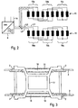
- the controllable magnet system 1 is part of a rail vehicle moving at the speed v F , the vehicle wheels or wheel sets 2 of which are guided by a running rail 3 of a wheel-rail system.
- the controllable magnet system 1 comprises a synchronously operated linear motor 4 made up of a number of electromagnets, the coils 5 of which are connected via a phase conductor 6 to a phase output 7a to 7c of a three-phase converter 8 and are thus connected to it on the AC side.
- the converter 8 is connected to the direct current side of an auxiliary operation converter 9, the alternating current side of which is connected via a transformer 10 to a current collector 11 of the rail vehicle.
- the connection between the converter 8 and the auxiliary operation converter 9 is, for example, a train bus bar provided in the rail vehicle for a DC voltage U DC of approximately 670 V.
- the converter 8 has a control input 12 to which a control device 13 is connected on the output side via a control line 14 .
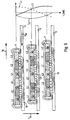
- the controllable magnet system 1 expediently from two connected in parallel Coil arrangements 15, 16 with nine individual coils 5 each.
- Three individual coils 5 of each coil arrangement 15, 16 form a coil group 15a to 15c or 16a to 16c, whose coils 5 are connected to the three phase outputs 7a to 7c and are connected in parallel overall.
- the Coils 5 of the coil groups 15a to 15c and 16a to 16c are as shown in FIG 5 - arranged directly next to each other Cylinder coils with the same or similar winding sense.
- the arrangement of the coil groups 15a to 15c and 16a to 16c takes place on both sides of a bogie or bogie 17 of the Rail vehicle between the wheels or wheelsets 2 and directly above the respective rail 3 of that shown in FIG 3 Two-rail system.
- the positioning of an individual Coil arrangement 15 'of a linear motor 4 in the middle of the bogie or bogie 17 'and above a reaction or Inference element 3 'in the form e.g. one between the (not shown) rails laid metal tape shows FIG 4.
- the holder of the coils 5 and thus the in Coil arrangements 15, 16 extending in the longitudinal direction of the rail takes place via a corresponding support system 18, which according to 3 on the bogie 17 between the wheel sets 2 and according to 4 in the middle of the bogie 17 attached to this is.
- the control device 13 receives the vehicle speed v F on the input side as a control parameter.
- the phase currents L1 to L3 in the respective coils 5 are set by the control device 13 such that the traveling field speed v W is equal in amount to the vehicle speed v F.
- the magnetic field lines emanating from the respective north pole N close via the air gap 19 and the rail 3 in the adjacent south pole S at the same location of the rail 3 , since the traveling field speed v W is equal to the vehicle speed v F of the rail vehicle moving against the traveling field direction.
- the north-south-north-south pole arrangement thus rolls over the rail 3 at the vehicle speed V F.
- the control of the individual magnet systems 1, preferably provided on several or all of the bogies 17 of the rail vehicle, by means of the control device 13 can also take place in a controlled manner according to different problems or strategies.
- the magnet system 1 can be activated in a location-specific manner, ie on certain sections of the route that are at risk of wind. Such sections of the route are, for example, tunnel exits and bridges. A wind measurement to control additional cross wind forces is then not necessary.
- a correspondingly large magnetic force F M becomes normal to the rail 3 or generated to the reaction element 3 ', which adds to the weight force F G , ie to its normal component, the rail vehicle.
- the or each controllable magnet system 1 can be activated by external wind speed detection depending on regionally determined wind speeds and after their transmission to the rail vehicle, for example to the existing train protection system.
- a corresponding control parameter P W for the wind speed is then fed to the control device 13.
- a spatially and temporally resolved wind speed detection can also take place selectively using the so-called nowcasting system.
- a relief measurement is carried out to determine the wheel relief, ie the operational decrease in the contact force F A of the wheel or wheel set 2 on the respective rail 3 (FIGS. 7 to 10).
- This relief detection can take place on the basis of a force measurement and / or a distance measurement, for example by B.
- the loading and / or relief of a car body 20 shown in FIG. 7 is determined on the basis of the rebounding from both sides of the car body 20 provided above the wheels 2 secondary springs 21 and 22.
- the bodywork relief and / or inclination can be measured and fed to the control device 13 as a measure of the relief as a control parameter P E.
- This rebound in particular of the leading dewatering of the rail vehicle, is determined by measuring the expansion amplitudes of the left and right secondary springs 21 and 22, wherein when a predetermined limit value of the measured expansion amplitudes is exceeded, the magnet system 1 is activated with a corresponding setting of the generated magnetic force F M .
- the expansion limit value represents a measure of the permissible loading or unloading of the car body 20.
- the difference in the expansion amplitudes can be formed, which then represents a measure of the car body inclination.
- the car body inclination can also be recorded directly, for example by means of an inclination sensor.
- Activation of the magnet system 1 and the setting of the magnetic force F M can also be carried out by means of a pressure measurement in the case of pneumatically operated secondary springs 21, 22, the pressure drop in the two secondary springs 21, 22 then serving as a measure for the relief and thus as a control parameter P E Control device 13 is supplied.
- Another alternative is to record the lateral acceleration of the rail vehicle.
- An unbalanced lateral acceleration of up to approx. 1.2 m / s 2 which usually occurs when cornering, leads to unilateral wheel set relief, which is correspondingly increased with the same effect of the side wind, which acts on the car body 20 with a wind force F S.
- the transverse acceleration can be detected in a manner not shown in more detail by means of an acceleration sensor, the magnet system 1 being activated when a limit value is reached.
- the limit value for activating the magnet system 1 is expediently determined in such a way that a critical limit value of, for example, 10% of the contact force or normal force F N of the rail vehicle is not reached.
- a magnet system 1 provided on the end car is preferably switched on depending on the loading condition and on the vehicle speed v F and, if appropriate, as a function of the measured lateral acceleration value.
- the magnetic force F M generated by this magnet system 1 thus in turn causes an increase in the normal force F N in the region of the end car and thus has a damping effect on such rolling movements.
- the controllable magnet system 1 is also activated if correspondingly low acceleration or braking forces occur due to a low coefficient of friction ⁇ . As a result, skidding or sliding between the wheels 2 and the rails 3 during acceleration or braking operations can be reliably prevented. Since a start-up and brake control device for detecting skidding or sliding movements is usually already present on such a rail vehicle, measured values recorded by the latter are supplied to control device 13 as control parameters P SG .
- controllable magnet system 1 Since the controllable magnet system 1 generates a quasi-static traveling field and thus acts on the one hand without contact and on the other hand does not generate any driving or braking forces, this can also be permanently activated.
- FIG. 7 shows the increase in the normal force F N by the magnetic attraction force F M of the magnet system 1 acting perpendicular or normal to the rail 3
- FIG. 7 also shows the one-sided increase in the deflection amplitude of the right secondary spring 22, which is designed here as a pneumatic spring, for example.
- the wheels 2 of the car body 20 are shown lifted off the rails 3.
- the proportions F G / 2 of the weight force F G add up vectorially to the magnetic force F M acting on the respective rail 3.
- M K F S xh of the stabilizing restoring torque M R counteracting at height h with the force Fs.
- the decrease in the normal force F N of the rail vehicle and thus the decrease in the contact force F A of a wheel 2 compared to the rail 3 due to an operational relief due to z. B. illustrates the effect of an external force on the rail vehicle.
- the left half of the figure of FIG. 8 shows the maximum normal force F N resulting from a given vehicle mass and the resulting contact force F A , while the right half of the figure shows its decrease by the relief F E.
- the detection of the relief or relief force F E takes place by means of a force measurement, for which purpose a strain gauge 26 is attached to the wheel 2.
- the magnetic force F M of the traveling field is adjusted, ie more or less increased, as a function of the relief F E of this wheel 2 detected by means of the expansion strip 26 compared to the rail 3 assigned to it.
- control device 13 receives a control signal derived from this force measurement as control parameter P E.
- FIG. 9 shows, analogously to FIG. 8, the change in the normal force F N and the resulting decrease in the standing force F A when an operational relief F E occurs .
- a force measurement also takes place here and, depending on this, the magnetic force F M of the traveling field is set by means of the control device on the basis of the control parameter P E derived from the force measurement.
- the force is measured here by means of a load cell 27, which is arranged between a wheel or axle bearing 28 and a primary spring 29 provided between it and the bogie or bogie frame 17.
- the relief measurement can also be carried out by measuring the distance.
- a displacement measuring device 30 is arranged on the bogie frame 17, which detects the distance or the height H between the bogie frame 17 and the rail 3 by means of an optical or acoustic signal S W. From a change ⁇ H in the height H caused by a relief F E , which is detected by a change in the running time or a difference in the running time of the optical or acoustic signal S W , the control device 13 uses the control parameter P E derived from this displacement measurement to make the magnetic analog Force F M of the traveling field set.
- the proportionality factors on the one hand and the maximum normal force F G of the rail vehicle are known, so that the relief F E can be determined from a measured change in force or displacement and can be specified as control parameter P E of the control device 13. This then adjusts the magnetic force F M, which is the opposite of this, as a function of the relief F E detected by measurement.
Landscapes
- Engineering & Computer Science (AREA)
- Transportation (AREA)
- Mechanical Engineering (AREA)
- Physics & Mathematics (AREA)
- Electromagnetism (AREA)
- Power Engineering (AREA)
- Electric Propulsion And Braking For Vehicles (AREA)
Abstract
Description
- FIG 1
- schematisch ein steuerbares Magnetsystem (magnetische Schienenklammer) in Form eines Linearmotors zur Normalkrafterhöhung eines Schienenfahrzeugs,
- FIG 2
- eine bevorzugte elektrische Verschaltung einer aus Einzelspulen aufgebauten Elektromagnet-Anordnung mehrerer Linearmotoren des Magnetsystems,
- FIG 3
- in Draufsicht ein Drehgestell mit zwischen dessen Rädern symmetrisch angeordneter Spulenanordnung gemäß FIG 2,
- FIG 4
- in einer Darstellung gemäß FIG 3 ein Drehgestell mit mittig angeordnetem Linearmotor,
- FIG 5
- die Spulenanordnung gemäß FIG 3 oder 4 in Seitenansicht,
- FIG 6
- zu unterschiedlichen Zeitpunkten ein sich zwischen dem Magnetsystem und einer Schiene ausbildendes magnetisches Wanderfeld sowie die zugehörigen Phasenströme in einem Amplituden-Zeit-Diagramm,
- FIG 7
- die Kräfteverhältnisse infolge eines aktivierten Magnetsystems anhand einer Vorderansicht eines Schienenfahrzeugs mit geneigtem Wagenkasten,
- FIG 8
- schematisch eine Kraftmessung mittels eines an einem Fahrzeugrad angebrachten Dehnungsmessstreifen zur Einstellung der magnetischen Kraft des Wanderfeldes bei entlastetem (rechte Figurenhälfte) bzw. nicht entlastetem (linke Figurenhälfte) Fahrzeugrad,
- FIG 9
- in einer Darstellung gemäß FIG 8 eine Kraftmessung mittels einer zwischen einem Achslager und einer Primärfeder angeordneten Kraftmessdose, und
- FIG 10
- in einer Darstellung gemäß den Figuren 8 und 9 eine Wegmessung zur Einstellung der magnetischen Kraft des Wanderfeldes.
Claims (10)
- Verfahren zur Erhöhung der zwischen einem Schienenfahrzeug und der Schiene (3) wirkenden Normalkraft (FN), bei dem in einem Luftspalt (19) zwischen einem vom Schienenfahrzeug mitbewegten Magnetsystem (1) und der Schiene (3) ein magnetisches Wanderfeld erzeugt wird,
dadurch gekennzeichnet, dass eine der Fahrzeuggeschwindigkeit (vF) entgegengesetzt gleiche Wanderfeldgeschwindigkeit (vW) erzeugt wird, wobei die vom Wanderfeld erzeugte magnetische Kraft (FM) in Abhängigkeit von einer meßtechnisch erfassten Entlastung (FE) eines Fahrzeugrades (2) gegenüber der diesem zugeordneten Schiene (3) eingestellt wird. - Verfahren nach Anspruch 1,
dadurch gekennzeichnet, dass die Entlastung (FE) des Fahrzeugrades (2) gegenüber der Schiene (3) durch eine Kraft- und/oder Wegmessung erfasst wird. - Verfahren nach Anspruch 1 oder 2,
dadurch gekennzeichnet, dass die vom Wanderfeld erzeugte magnetische Kraft (FM) derart eingestellt wird, dass die meßtechnisch erfasste Entlastung (FE) kompensiert wird. - Vorrichtung zur Erhöhung der zwischen einem Schienenfahrzeug und der Schiene (3) wirkenden Normalkraft (FN), mit einem vom Fahrzeug mitbewegten steuerbaren Magnetsystem (1), das in einem Luftspalt (19) zwischen dem Fahrzeug und der Schiene (3) ein magnetisches Wanderfeld erzeugt,
gekennzeichnet durch eine mit dem Magnetsystem (1) verbundene Steuereinrichtung (13), der eingangsseitig die erfasste Fahrzeuggeschwindigkeit (vF) zur Einstellung einer dieser entgegengerichtet gleichen Wanderfeldgeschwindigkeit (vW) und mindestens ein die Entlastung (FE) eines Fahrzeugrades (2) gegenüber der diesem zugeordneten Schiene (3) repräsentierender Steuerparameter (Pn) zur Einstellung der vom Wanderfeld erzeugten magnetischen Kraft (FM) zugeführt ist. - Vorrichtung nach Anspruch 4,
dadurch gekennzeichnet, dass das steuerbare Magnetsystem (1) einen Linearmotor (4) mit einer Anzahl von einzeln erregbaren Elektromagneten umfaßt, deren Spulen (5) von mindestens einem eingangsseitig mit der Steuereinrichtung (13) verbundenen Umrichter (8) gespeist sind. - Vorrichtung nach Anspruch 5,
gekennzeichnet durch einen mehrphasigen Umrichter (8), dessen jeweiliger Phasenausgang (7a bis 7c) mit einer dieser Phase (L1,L2,L3) zugeordneten Spule (5) verbunden ist. - Vorrichtung nach Anspruch 5 oder 6,
dadurch gekennzeichnet, dass mehrere Spulengruppen (15a bis 15c, 16a bis 16c) mit jeweils einer der Anzahl der Phasen (L1,L2,L3) entsprechenden Anzahl von Spulen (5) vorgesehen sind, wobei die den einzelnen Phasen (L1,L2,L3) zugeordneten Spulen (5) der Spulengruppen (15a bis 15c, 16a bis 16c) miteinander verbunden sind. - Vorrichtung nach einem der Ansprüche 4 bis 7,
dadurch gekennzeichnet, dass im Bereich mehrerer Radanordnungen (2) des Schienenfahrzeugs jeweils mindestens eine mit diesem fest verbundene steuerbare Magnetanordnung (1) vorgesehen ist, deren auf ein Reaktionselement (3,3') wirkende magnetische Kraft (FM) individuell einstellbar ist. - Vorrichtung nach einem der Ansprüche 4 bis 8,
dadurch gekennzeichnet, dass bei der Ausführung des Schienenfahrzeugs für ein Zwei-Schienen-System mit jeweils mindestens einen Radsatz (2) aufweisendem Drehgestell (17) beidseitig des Drehgestells (17) eine mehrphasige Spulenanordnung (15,16) vorgesehen ist, deren Spulen (5) unter Bildung des Luftspaltes (19) zwischen diesen und der jeweiligen Schiene (3) an einem am Drehgestell (17) befestigten Tragsystem (18) gehalten sind. - Vorrichtung nach einem der Ansprüche 4 bis 8,
dadurch gekennzeichnet, dass ein jeweils mindestens einen Radsatz (2) aufweisendes Drehgestell (17') etwa in dessen Mitte eine mehrphasige Spulenanordnung (15') aufweist, deren spulen (5) unter Bildung des Luftspaltes (19) zwischen diesen und einem mittig zwischen den Schienen (3) angeordneten Reaktionselement (3') an einem am Drehgestell (17') befestigten Tragsystem (18) gehalten sind.
Applications Claiming Priority (2)
| Application Number | Priority Date | Filing Date | Title |
|---|---|---|---|
| DE19919967 | 1999-04-30 | ||
| DE19919967 | 1999-04-30 |
Publications (2)
| Publication Number | Publication Date |
|---|---|
| EP1048542A2 true EP1048542A2 (de) | 2000-11-02 |
| EP1048542A3 EP1048542A3 (de) | 2000-12-06 |
Family
ID=7906584
Family Applications (1)
| Application Number | Title | Priority Date | Filing Date |
|---|---|---|---|
| EP00108466A Withdrawn EP1048542A3 (de) | 1999-04-30 | 2000-04-18 | Verfahren und Vorrichtung zur Erhöhung der Normalkraft eines Schienenfahrzeugs |
Country Status (1)
| Country | Link |
|---|---|
| EP (1) | EP1048542A3 (de) |
Cited By (8)
| Publication number | Priority date | Publication date | Assignee | Title |
|---|---|---|---|---|
| CN101596909A (zh) * | 2009-07-01 | 2009-12-09 | 周原 | 粘着力可控的轨道车辆动力转向架 |
| CN102501873A (zh) * | 2011-11-03 | 2012-06-20 | 同济大学 | 一种轨道车辆轮轨增载装置 |
| EP2727790A1 (de) | 2012-10-30 | 2014-05-07 | Bombardier Transportation GmbH | Fahrgestelleinheit mit verstellbarer Radkontaktkraft |
| CN109677426A (zh) * | 2018-12-18 | 2019-04-26 | 同济大学 | 一种用于提高列车轮轨粘着力的系统 |
| CN114132186A (zh) * | 2021-11-25 | 2022-03-04 | 江西理工大学 | 一种稀土永磁悬浮轨道悬浮力调控系统及方法 |
| CN117021962A (zh) * | 2023-10-07 | 2023-11-10 | 成都尚华电气有限公司 | 一种基于短定子直线电机驱动的列车、系统及控制方法 |
| CN117657223A (zh) * | 2022-08-25 | 2024-03-08 | 比亚迪股份有限公司 | 防滑装置和轨道车辆 |
| DE102022210339A1 (de) * | 2022-09-29 | 2024-04-04 | Siemens Mobility GmbH | Sandstreuanlage für ein Schienenfahrzeug |
Citations (2)
| Publication number | Priority date | Publication date | Assignee | Title |
|---|---|---|---|---|
| US4236455A (en) | 1973-08-14 | 1980-12-02 | Dos Santos Jose P | Method and apparatus for generating linear electromagnetic travelling fields for driving and increasing the adhesive load of railway motored vehicles |
| DE29714319U1 (de) | 1996-09-12 | 1997-12-04 | Siemens AG, 80333 München | Bremssystem |
Family Cites Families (2)
| Publication number | Priority date | Publication date | Assignee | Title |
|---|---|---|---|---|
| FR2018507A1 (de) * | 1968-09-20 | 1970-05-29 | Hitachi Ltd | |
| JPH09322316A (ja) * | 1996-05-30 | 1997-12-12 | Toyo Electric Mfg Co Ltd | リニアモータ車両 |
-
2000
- 2000-04-18 EP EP00108466A patent/EP1048542A3/de not_active Withdrawn
Patent Citations (2)
| Publication number | Priority date | Publication date | Assignee | Title |
|---|---|---|---|---|
| US4236455A (en) | 1973-08-14 | 1980-12-02 | Dos Santos Jose P | Method and apparatus for generating linear electromagnetic travelling fields for driving and increasing the adhesive load of railway motored vehicles |
| DE29714319U1 (de) | 1996-09-12 | 1997-12-04 | Siemens AG, 80333 München | Bremssystem |
Cited By (10)
| Publication number | Priority date | Publication date | Assignee | Title |
|---|---|---|---|---|
| CN101596909A (zh) * | 2009-07-01 | 2009-12-09 | 周原 | 粘着力可控的轨道车辆动力转向架 |
| CN102501873A (zh) * | 2011-11-03 | 2012-06-20 | 同济大学 | 一种轨道车辆轮轨增载装置 |
| CN102501873B (zh) * | 2011-11-03 | 2014-06-25 | 同济大学 | 一种轨道车辆轮轨增载装置 |
| EP2727790A1 (de) | 2012-10-30 | 2014-05-07 | Bombardier Transportation GmbH | Fahrgestelleinheit mit verstellbarer Radkontaktkraft |
| CN109677426A (zh) * | 2018-12-18 | 2019-04-26 | 同济大学 | 一种用于提高列车轮轨粘着力的系统 |
| CN114132186A (zh) * | 2021-11-25 | 2022-03-04 | 江西理工大学 | 一种稀土永磁悬浮轨道悬浮力调控系统及方法 |
| CN117657223A (zh) * | 2022-08-25 | 2024-03-08 | 比亚迪股份有限公司 | 防滑装置和轨道车辆 |
| DE102022210339A1 (de) * | 2022-09-29 | 2024-04-04 | Siemens Mobility GmbH | Sandstreuanlage für ein Schienenfahrzeug |
| CN117021962A (zh) * | 2023-10-07 | 2023-11-10 | 成都尚华电气有限公司 | 一种基于短定子直线电机驱动的列车、系统及控制方法 |
| CN117021962B (zh) * | 2023-10-07 | 2024-01-19 | 成都尚华电气有限公司 | 一种基于短定子直线电机驱动的列车、系统及控制方法 |
Also Published As
| Publication number | Publication date |
|---|---|
| EP1048542A3 (de) | 2000-12-06 |
Similar Documents
| Publication | Publication Date | Title |
|---|---|---|
| DE10009331C2 (de) | Magnetische Bremse mit Aktuatoren zur Einstellung des Abstandes von der Schienenoberkante | |
| DE3111087C2 (de) | Einzelradanordnung für Eisenbahnfahrzeuge | |
| DE102007003118A1 (de) | Magnetschwebebahn und Verfahren zu deren Betrieb | |
| DE3004704A1 (de) | Magnetschwebebahn | |
| DE19953677C1 (de) | Verfahren und Vorrichtung zur Erkennung einer Entgleisung eines spurgebundenen Fahrzeugs | |
| DE2255254B2 (de) | Aufhängevorrichtung fur einen Linear Induktor an dem Drehgestell eines Schienenfahrzeugs | |
| EP1048542A2 (de) | Verfahren und Vorrichtung zur Erhöhung der Normalkraft eines Schienenfahrzeugs | |
| EP0870664A2 (de) | Verfahren und Einrichtung zur Radsatzführung von Schienen-Fahrzeugen | |
| DE2614166B2 (de) | Radsatz für Schienenfahrzeuge | |
| EP0560262A1 (de) | Verfahren zur Erzeugung belastungsabhängiger Schaltsignale an Eisenbahnschienen | |
| DE2512008A1 (de) | Lagervorrichtung fuer wagen auf laufgestellen, insbesondere fuer schienenfahrzeuge | |
| DE3019573C2 (de) | Spurführung für Radsätze eines Schienenfahrzeug-Drehgestells | |
| DE2127047A1 (de) | Verfahren zur dynamischen Entkopplung eines schienengebundenen Fahrzeuges von seinen Schienen und Einrichtung zur Durchführung des Verfahrens | |
| EP0290930B1 (de) | Bahnsystem zum Betrieb eines entgleisungssicheren Hochgeschwindigkeits-Schienenfahrzeuges | |
| EP0724998B1 (de) | Magnetische Bremse, insbesondere lineare Wirbelstrombremse | |
| EP0860340B1 (de) | Verfahren und Vorrichtung zur Generierung eines Sensorsignales | |
| DE102014203689B4 (de) | Fahrwerk für ein Schienenfahrzeug | |
| EP0826548B1 (de) | Verfahren zur Regelung des elektrischen Antriebs eines Schienenfahrzeugs | |
| DE2315948A1 (de) | Vorrichtung zur seitenfuehrung von radsaetzen von schienenfahrzeugen | |
| DE2848398B1 (de) | Spurfuehrung eines Radsatzes fuer Schienenfahrzeuge | |
| EP1875028A1 (de) | Verfahren zum betrieb einer steuerungseinrichtung für eine tür und steuerungseinrichtung hierzu | |
| DE2257560A1 (de) | Radsatzfahrwerk fuer schienenfahrzeuge mit magnetischer oder elektrodynamischer fuehrung im gleis | |
| EP1193154A1 (de) | Verfahren und Vorrichtung zur Stabilisierung des Wellenlaufes von Eisenbahnradsätzen | |
| DE2558104A1 (de) | Hybrides trag- und fuehrungssystem fuer spurgebundene fahrzeuge | |
| DE2251978A1 (de) | Suspensions- und daempfungseinrichtung fuer auf raedern gelagerte fahrzeuge |
Legal Events
| Date | Code | Title | Description |
|---|---|---|---|
| PUAI | Public reference made under article 153(3) epc to a published international application that has entered the european phase |
Free format text: ORIGINAL CODE: 0009012 |
|
| PUAL | Search report despatched |
Free format text: ORIGINAL CODE: 0009013 |
|
| AK | Designated contracting states |
Kind code of ref document: A2 Designated state(s): AT BE CH CY DE DK ES FI FR GB GR IE IT LI LU MC NL PT SE |
|
| AX | Request for extension of the european patent |
Free format text: AL;LT;LV;MK;RO;SI |
|
| AK | Designated contracting states |
Kind code of ref document: A3 Designated state(s): AT BE CH CY DE DK ES FI FR GB GR IE IT LI LU MC NL PT SE |
|
| AX | Request for extension of the european patent |
Free format text: AL;LT;LV;MK;RO;SI |
|
| AKX | Designation fees paid | ||
| STAA | Information on the status of an ep patent application or granted ep patent |
Free format text: STATUS: THE APPLICATION IS DEEMED TO BE WITHDRAWN |
|
| 18D | Application deemed to be withdrawn |
Effective date: 20010607 |
|
| REG | Reference to a national code |
Ref country code: DE Ref legal event code: 8566 |