EP1048040B1 - Vorrichtung zur nothandbetätigung bei schaltmagneten - Google Patents
Vorrichtung zur nothandbetätigung bei schaltmagneten Download PDFInfo
- Publication number
- EP1048040B1 EP1048040B1 EP98954316A EP98954316A EP1048040B1 EP 1048040 B1 EP1048040 B1 EP 1048040B1 EP 98954316 A EP98954316 A EP 98954316A EP 98954316 A EP98954316 A EP 98954316A EP 1048040 B1 EP1048040 B1 EP 1048040B1
- Authority
- EP
- European Patent Office
- Prior art keywords
- pole core
- armature
- pole
- pull member
- threaded bolt
- Prior art date
- Legal status (The legal status is an assumption and is not a legal conclusion. Google has not performed a legal analysis and makes no representation as to the accuracy of the status listed.)
- Expired - Lifetime
Links
Images


Classifications
-
- H—ELECTRICITY
- H01—ELECTRIC ELEMENTS
- H01F—MAGNETS; INDUCTANCES; TRANSFORMERS; SELECTION OF MATERIALS FOR THEIR MAGNETIC PROPERTIES
- H01F7/00—Magnets
- H01F7/06—Electromagnets; Actuators including electromagnets
- H01F7/08—Electromagnets; Actuators including electromagnets with armatures
- H01F7/16—Rectilinearly-movable armatures
- H01F7/1607—Armatures entering the winding
Definitions
- the invention relates to a device for emergency manual operation in the case of switching magnets, whose armature in the pole tube by the force of a spring arrangement in an end position and by magnetic field excitation against the spring force into a second End position is movable, with a tension member axially displaceable in the pole core, which is movable by means of a manual actuating device and one with the anchor cooperating driver to this against the spring force to move to its second end position.
- the invention has for its object a device for emergency manual operation to create, which are compared to the known such devices characterized by a simpler structure and reduced assembly effort.
- this object is according to the invention solved in that the armature, the pole core, the spring arrangement, the Tension member and the actuator to a prefabricated unit in Form of a cartridge are united by the inner, open end of the pole tube forth in this can be used and connected to it that the pole core Pole tube closes at its inner end.
- connection to the pole tube is particularly simple if the pole core has an annular groove worked into its circumference and through Crimping the end of the pole tube into the annular groove can be connected to it.
- the actuating device can be used as Actuator for the axial displacement movement of the tension member a threaded bolt have a guide for the with an internal thread section Interacting axial hole in the pole core.
- the emergency operation can be convenient and safely done by manually turning the threaded bolt, if this has a screw head accessible at the free end of the pole core has, for example, be provided with an extensive knurling can.
- the tension member is preferably a one-piece extension of the threaded bolt formed, which extends beyond the inner end of the pole core into an anchor trained axial bore extends.
- the extension of the threaded bolt forming the tension member preferably has which is due to a sealing arrangement located in the axial bore of the pole core extends into the axial bore formed in the armature, an outer diameter tapered relative to the adjacent part of the threaded bolt on. This ensures that there is also an emergency operation can easily be managed against high prevailing working pressures.
- the assembly is particularly easy if as a driver a free end of the extension of the tension member flared rim is provided.
- a shape of the free end of the tension member is particularly easy to manufacture during assembly if the free end of the Tension member has an axial blind bore and after assembly of the individual parts of the cartridge-like assembly, the mouth of the blind hole is deformed outwards as a flanged edge.
- the invention is based on one shown in the drawing Embodiment explained in detail.
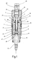
- the magnet is one of the so-called "pulling" type, i.e. his anchor 3, which is by means of a spring arrangement 5 is pressed away from the pole core 7 into an end position, which is shown in FIG. 1 is shown, when the magnetic winding is excited against the force of the spring arrangement 5 pulled to the pole core 7, as shown in Fig. 2.
- the pole tube 1 is for magnetic decoupling through a welding point 4 divided.
- the armature 3 is over a spring ring 49, which is seated in an annular groove 9, which in an axial bore 11 the armature 3 is formed, connected to an actuating pin 13, see in particular Fig. 3.
- the actuating pin 13 points for the interaction with the spring ring 49 also an annular groove 35 and extends from Armature 3 away beyond the adjacent end of the pole tube 1 and serves as Actuator for a relevant switching operation, for example Valve actuation in a hydraulic system.
- FIG. 4 All the individual parts accommodated in the interior of the pole tube 1 form one prefabricated, cartridge-like unit, which is shown in Fig. 4 for itself.
- This cartridge is from the open end 15 of the pole tube 1 in this way used that the pole core 7 closes the pole tube 1 at the end 15.
- the connection between pole tube 1 and pole core 7 takes place by crimping end 15 of the pole tube 1 in a circumferential annular groove 17 of the pole core 7.
- Another circumferential annular groove 19 in the pole core 7 takes an O-ring 21 for the seal between pole core 7 and pole tube 1.
- the cartridge shown in Fig. 4 contains in addition to the pole core 7, the armature 3, the attached actuating mandrel 13 and the spring assembly 5 also a device for emergency manual operation.
- This has a threaded bolt 23 on, the threaded portion 24 with an internal thread 25 in an axial bore 27 is screwed into the pole core 7 and one at the end of the pole core 7
- Accessible screw head 29 which has a knurling for the manual rotary control is provided.
- the threaded bolt 23 is on its side facing away from the screw head 29 extended by a tapered end portion 31 which extends through a sealing arrangement 39 passing through an enlarged portion of the bore 27 of the pole core sits, extends into the axial bore 11 of the armature 3.
- the free End of the extension 31 passes through a local constriction 43, through which in the bore 11 a facing the pole core 7 first annular shoulder surface 41 and a second annular shoulder surface 45 facing away from the pole core 7 is formed, which is best seen from Fig. 3.
- the free end of the extension 31 has an end-side, coaxial blind bore 50, the mouth of which is flanged to form a flanged edge 47 to the outside.
- the flanged edge 47 forms a driver which at one Emergency operation, i.e. when unscrewing (upwards in the drawings) of the bolt 23 on the annular shoulder surface 45 of the local constriction 43 of the bore 11 of the armature 3 comes to rest against it the force of the spring arrangement 5 pulls on the pole core 7. This position the individual parts is shown in Fig. 4.
- the length of the tension member is dimensioned so that the end flanged edge 47 of the extension 31 when the screw bolt 23 is screwed in, ie not activated manual override (Fig. 1 to 3), in such a relationship to Ring shoulder surface 45 is that the normal working stroke of the armature 3rd is possible without hindrance.
- the compression spring arrangement 5 is in the Axial bore 11 of the armature 3 on the one hand on the formed by the constriction 43, the pole core 7 facing ring shoulder surface 41 supported while the other end on one lying against the sealing arrangement 39 in the pole core 7 Washer 51 is supported.
Landscapes
- Physics & Mathematics (AREA)
- Electromagnetism (AREA)
- Engineering & Computer Science (AREA)
- Power Engineering (AREA)
- Electromagnets (AREA)
- Gear-Shifting Mechanisms (AREA)
- Driving Mechanisms And Operating Circuits Of Arc-Extinguishing High-Tension Switches (AREA)
Applications Claiming Priority (3)
| Application Number | Priority Date | Filing Date | Title |
|---|---|---|---|
| DE19801201A DE19801201A1 (de) | 1998-01-15 | 1998-01-15 | Vorrichtung zur Nothandbetätigung bei Schaltmagneten |
| DE19801201 | 1998-01-15 | ||
| PCT/EP1998/006259 WO1999036926A1 (de) | 1998-01-15 | 1998-10-01 | Vorrichtung zur nothandbetätigung bei schaltmagneten |
Publications (2)
| Publication Number | Publication Date |
|---|---|
| EP1048040A1 EP1048040A1 (de) | 2000-11-02 |
| EP1048040B1 true EP1048040B1 (de) | 2002-07-24 |
Family
ID=7854628
Family Applications (1)
| Application Number | Title | Priority Date | Filing Date |
|---|---|---|---|
| EP98954316A Expired - Lifetime EP1048040B1 (de) | 1998-01-15 | 1998-10-01 | Vorrichtung zur nothandbetätigung bei schaltmagneten |
Country Status (6)
| Country | Link |
|---|---|
| US (1) | US6310530B1 (sk) |
| EP (1) | EP1048040B1 (sk) |
| JP (1) | JP4170589B2 (sk) |
| DE (2) | DE19801201A1 (sk) |
| ES (1) | ES2181293T3 (sk) |
| WO (1) | WO1999036926A1 (sk) |
Families Citing this family (9)
| Publication number | Priority date | Publication date | Assignee | Title |
|---|---|---|---|---|
| DE20013052U1 (de) | 2000-07-28 | 2000-11-23 | Festo AG & Co, 73734 Esslingen | Handbetätigungseinrichtung für Ventile |
| US6669166B2 (en) | 2000-07-28 | 2003-12-30 | Nippon Soken, Inc. | Electromagnetic valve |
| DE10163929A1 (de) | 2001-12-22 | 2003-07-03 | Obrist Engineering Gmbh Lusten | Nadelventil |
| ITRE20100004U1 (it) * | 2010-04-21 | 2011-10-22 | Brevini Fluid Power Spa | Asta comando manuale di valvole di distribuzione |
| US9062790B2 (en) | 2012-08-24 | 2015-06-23 | Kohler Co. | System and method to position and retain a sensor in a faucet spout |
| US9074698B2 (en) | 2012-08-24 | 2015-07-07 | Kohler Co. | System and method to detect and communicate faucet valve position |
| US9341278B2 (en) * | 2012-08-24 | 2016-05-17 | Kohler Co. | System and method for manually overriding a solenoid valve of a faucet |
| CN110349742B (zh) * | 2019-07-12 | 2021-04-09 | 兰州科近泰基新技术有限责任公司 | 一种多封头细长高频水套的制造方法 |
| EP3839307A1 (en) * | 2019-12-20 | 2021-06-23 | Dana Motion Systems Italia S.R.L. | Valve override assembly, valve, and method |
Family Cites Families (10)
| Publication number | Priority date | Publication date | Assignee | Title |
|---|---|---|---|---|
| US3900810A (en) | 1974-06-26 | 1975-08-19 | Texas Instruments Inc | Time delay capsule for magnetic circuit breaker |
| DE7631794U1 (de) * | 1976-10-12 | 1977-02-03 | Arnold, Willy, 7119 Niedernhall | Magnetventil |
| DE3243999A1 (de) | 1982-11-27 | 1984-05-30 | bso Steuerungstechnik GmbH, 6603 Sulzbach | "betaetigungsmagnet, insbesondere hubmagnet" |
| US4544128A (en) * | 1983-02-24 | 1985-10-01 | Imperial Clevite Inc. | Cartridge solenoid valve with manual override |
| DE3317226A1 (de) | 1983-05-11 | 1984-11-15 | bso Steuerungstechnik GmbH, 6603 Sulzbach | Betaetigungsmagnet |
| US4679017A (en) | 1986-03-19 | 1987-07-07 | Synchro-Start Products, Inc. | Emergency manual actuation mechanism for a solenoid |
| US4871989A (en) * | 1988-04-15 | 1989-10-03 | Synchro-Start Products, Inc. | Solenoid with manual actuation mechanism |
| US5271599A (en) * | 1990-09-28 | 1993-12-21 | Kolchinsky Abel E | Modular solenoid valve |
| DE9200549U1 (de) | 1992-01-18 | 1992-03-19 | Binder Magnete GmbH, 78048 Villingen-Schwenningen | Gleichstrom-Hubmagnet |
| US5842679A (en) * | 1997-02-20 | 1998-12-01 | Sterling Hydraulics, Inc. | Adjustable stroke solenoid operated cartridge valve |
-
1998
- 1998-01-15 DE DE19801201A patent/DE19801201A1/de not_active Ceased
- 1998-10-01 WO PCT/EP1998/006259 patent/WO1999036926A1/de active IP Right Grant
- 1998-10-01 JP JP2000540548A patent/JP4170589B2/ja not_active Expired - Fee Related
- 1998-10-01 ES ES98954316T patent/ES2181293T3/es not_active Expired - Lifetime
- 1998-10-01 EP EP98954316A patent/EP1048040B1/de not_active Expired - Lifetime
- 1998-10-01 DE DE59804937T patent/DE59804937D1/de not_active Expired - Lifetime
- 1998-10-01 US US09/600,300 patent/US6310530B1/en not_active Expired - Lifetime
Also Published As
| Publication number | Publication date |
|---|---|
| US6310530B1 (en) | 2001-10-30 |
| EP1048040A1 (de) | 2000-11-02 |
| JP4170589B2 (ja) | 2008-10-22 |
| ES2181293T3 (es) | 2003-02-16 |
| JP2002509370A (ja) | 2002-03-26 |
| DE59804937D1 (de) | 2002-08-29 |
| DE19801201A1 (de) | 1999-07-29 |
| WO1999036926A1 (de) | 1999-07-22 |
Similar Documents
| Publication | Publication Date | Title |
|---|---|---|
| DE602005001726T2 (de) | Magnetventil zur Installation auf einem unter Gasdruck stehenden Flüssigkeitsbehälter | |
| DE2011409C3 (de) | Ventilschnellkupplung fur zwei gas- oder flussigkeitsfuhrende Leitungen | |
| DE19700979A1 (de) | Magnetventil | |
| DE102005042679A1 (de) | Bypassventil für Verbrennungskraftmaschinen | |
| DE19943066A1 (de) | Elektromagnetisch betätigbares, hydraulisches Proportionalventil | |
| EP2652376B1 (de) | Elektromagnetventil | |
| EP1048040B1 (de) | Vorrichtung zur nothandbetätigung bei schaltmagneten | |
| DE69323686T2 (de) | Rückschlagventil-Betätigungsvorrichtung | |
| DE102007005916A1 (de) | Doppelankermagnetventil mit zwei Ventilöffnungen und mindestens einem die Ventilöffnungen verbindenden Kanal | |
| EP2378167B1 (de) | Verriegelungseinheit | |
| DE3317226C2 (sk) | ||
| EP2959180B1 (de) | Kolben-zylinder-einheit | |
| EP1361325B1 (de) | Betätiger für Verschlüsse an Fahrzeugen | |
| DE4438334A1 (de) | Magnetventil mit Druckbegrenzung für schlupfgeregelte Kraftfahrzeug-Bremsanlagen | |
| DE3546865C2 (de) | Kolben-Zylinder-Anordnung | |
| DE102020124188B4 (de) | Parksperre zum Feststellen eines Getriebes, insbesondere eines Kraftfahrzeuggetriebes, sowie Getriebe | |
| DE102008061414B4 (de) | Verfahren zum Herstellen einer elektromagnetischen Betätigungsvorrichtung, insbesondere zum Betätigen von Ventilen, sowie nach dem Verfahren hergestellte Betätigungsvorrichtung | |
| DE3103698A1 (de) | Mechanische verriegelung | |
| WO1997018568A1 (de) | Hubmagnetanordnung | |
| DE2425946A1 (de) | Doppelmagnetventil | |
| DE69517308T2 (de) | Magnetischer betätiger mit mehrfach luftspalten | |
| DE19734533C2 (de) | Ventil | |
| DE4446625C1 (de) | Verpreßventil für einen Injektionsbohranker | |
| DE19812044C1 (de) | Gewindeeinsatz | |
| DE102009051574A1 (de) | Magnetventil |
Legal Events
| Date | Code | Title | Description |
|---|---|---|---|
| PUAI | Public reference made under article 153(3) epc to a published international application that has entered the european phase |
Free format text: ORIGINAL CODE: 0009012 |
|
| 17P | Request for examination filed |
Effective date: 20000520 |
|
| AK | Designated contracting states |
Kind code of ref document: A1 Designated state(s): CH DE ES FR GB IE IT LI MC |
|
| GRAG | Despatch of communication of intention to grant |
Free format text: ORIGINAL CODE: EPIDOS AGRA |
|
| GRAG | Despatch of communication of intention to grant |
Free format text: ORIGINAL CODE: EPIDOS AGRA |
|
| 17Q | First examination report despatched |
Effective date: 20011207 |
|
| GRAG | Despatch of communication of intention to grant |
Free format text: ORIGINAL CODE: EPIDOS AGRA |
|
| GRAH | Despatch of communication of intention to grant a patent |
Free format text: ORIGINAL CODE: EPIDOS IGRA |
|
| GRAH | Despatch of communication of intention to grant a patent |
Free format text: ORIGINAL CODE: EPIDOS IGRA |
|
| GRAA | (expected) grant |
Free format text: ORIGINAL CODE: 0009210 |
|
| AK | Designated contracting states |
Kind code of ref document: B1 Designated state(s): CH DE ES FR GB IE IT LI MC |
|
| REG | Reference to a national code |
Ref country code: GB Ref legal event code: FG4D Free format text: NOT ENGLISH |
|
| REG | Reference to a national code |
Ref country code: CH Ref legal event code: NV Representative=s name: ISLER & PEDRAZZINI AG Ref country code: CH Ref legal event code: EP |
|
| GBT | Gb: translation of ep patent filed (gb section 77(6)(a)/1977) |
Effective date: 20020724 |
|
| REG | Reference to a national code |
Ref country code: IE Ref legal event code: FG4D Free format text: GERMAN |
|
| REF | Corresponds to: |
Ref document number: 59804937 Country of ref document: DE Date of ref document: 20020829 |
|
| ET | Fr: translation filed | ||
| REG | Reference to a national code |
Ref country code: ES Ref legal event code: FG2A Ref document number: 2181293 Country of ref document: ES Kind code of ref document: T3 |
|
| PLBE | No opposition filed within time limit |
Free format text: ORIGINAL CODE: 0009261 |
|
| STAA | Information on the status of an ep patent application or granted ep patent |
Free format text: STATUS: NO OPPOSITION FILED WITHIN TIME LIMIT |
|
| 26N | No opposition filed |
Effective date: 20030425 |
|
| PGFP | Annual fee paid to national office [announced via postgrant information from national office to epo] |
Ref country code: MC Payment date: 20050905 Year of fee payment: 8 |
|
| PGFP | Annual fee paid to national office [announced via postgrant information from national office to epo] |
Ref country code: GB Payment date: 20050907 Year of fee payment: 8 |
|
| PGFP | Annual fee paid to national office [announced via postgrant information from national office to epo] |
Ref country code: ES Payment date: 20051003 Year of fee payment: 8 |
|
| PGFP | Annual fee paid to national office [announced via postgrant information from national office to epo] |
Ref country code: FR Payment date: 20051026 Year of fee payment: 8 Ref country code: CH Payment date: 20051026 Year of fee payment: 8 |
|
| PG25 | Lapsed in a contracting state [announced via postgrant information from national office to epo] |
Ref country code: MC Free format text: LAPSE BECAUSE OF NON-PAYMENT OF DUE FEES Effective date: 20061031 Ref country code: LI Free format text: LAPSE BECAUSE OF NON-PAYMENT OF DUE FEES Effective date: 20061031 Ref country code: CH Free format text: LAPSE BECAUSE OF NON-PAYMENT OF DUE FEES Effective date: 20061031 |
|
| REG | Reference to a national code |
Ref country code: CH Ref legal event code: PL |
|
| GBPC | Gb: european patent ceased through non-payment of renewal fee |
Effective date: 20061001 |
|
| REG | Reference to a national code |
Ref country code: FR Ref legal event code: ST Effective date: 20070629 |
|
| PG25 | Lapsed in a contracting state [announced via postgrant information from national office to epo] |
Ref country code: GB Free format text: LAPSE BECAUSE OF NON-PAYMENT OF DUE FEES Effective date: 20061001 |
|
| REG | Reference to a national code |
Ref country code: ES Ref legal event code: FD2A Effective date: 20061002 |
|
| PG25 | Lapsed in a contracting state [announced via postgrant information from national office to epo] |
Ref country code: FR Free format text: LAPSE BECAUSE OF NON-PAYMENT OF DUE FEES Effective date: 20061031 Ref country code: ES Free format text: LAPSE BECAUSE OF NON-PAYMENT OF DUE FEES Effective date: 20061002 |
|
| PGFP | Annual fee paid to national office [announced via postgrant information from national office to epo] |
Ref country code: IE Payment date: 20090928 Year of fee payment: 12 |
|
| REG | Reference to a national code |
Ref country code: IE Ref legal event code: MM4A |
|
| PG25 | Lapsed in a contracting state [announced via postgrant information from national office to epo] |
Ref country code: IE Free format text: LAPSE BECAUSE OF NON-PAYMENT OF DUE FEES Effective date: 20101001 |
|
| PGFP | Annual fee paid to national office [announced via postgrant information from national office to epo] |
Ref country code: IT Payment date: 20131007 Year of fee payment: 16 |
|
| PG25 | Lapsed in a contracting state [announced via postgrant information from national office to epo] |
Ref country code: IT Free format text: LAPSE BECAUSE OF NON-PAYMENT OF DUE FEES Effective date: 20141001 |
|
| PGFP | Annual fee paid to national office [announced via postgrant information from national office to epo] |
Ref country code: DE Payment date: 20171031 Year of fee payment: 20 |
|
| REG | Reference to a national code |
Ref country code: DE Ref legal event code: R071 Ref document number: 59804937 Country of ref document: DE |