EP1047592B1 - Elektrische antriebseinrichtung für schiffe - Google Patents
Elektrische antriebseinrichtung für schiffe Download PDFInfo
- Publication number
- EP1047592B1 EP1047592B1 EP98966573A EP98966573A EP1047592B1 EP 1047592 B1 EP1047592 B1 EP 1047592B1 EP 98966573 A EP98966573 A EP 98966573A EP 98966573 A EP98966573 A EP 98966573A EP 1047592 B1 EP1047592 B1 EP 1047592B1
- Authority
- EP
- European Patent Office
- Prior art keywords
- housing
- stator
- permanent magnets
- rotor
- disposed
- Prior art date
- Legal status (The legal status is an assumption and is not a legal conclusion. Google has not performed a legal analysis and makes no representation as to the accuracy of the status listed.)
- Expired - Lifetime
Links
- 230000001360 synchronised effect Effects 0.000 claims description 12
- 239000007787 solid Substances 0.000 claims description 2
- 238000003475 lamination Methods 0.000 claims 1
- 238000004804 winding Methods 0.000 description 14
- 238000001816 cooling Methods 0.000 description 11
- 239000007921 spray Substances 0.000 description 3
- XLYOFNOQVPJJNP-UHFFFAOYSA-N water Substances O XLYOFNOQVPJJNP-UHFFFAOYSA-N 0.000 description 3
- 230000004907 flux Effects 0.000 description 2
- 230000005284 excitation Effects 0.000 description 1
- 239000002184 metal Substances 0.000 description 1
Images


Classifications
-
- H—ELECTRICITY
- H02—GENERATION; CONVERSION OR DISTRIBUTION OF ELECTRIC POWER
- H02K—DYNAMO-ELECTRIC MACHINES
- H02K5/00—Casings; Enclosures; Supports
- H02K5/02—Casings or enclosures characterised by the material thereof
-
- H—ELECTRICITY
- H02—GENERATION; CONVERSION OR DISTRIBUTION OF ELECTRIC POWER
- H02K—DYNAMO-ELECTRIC MACHINES
- H02K9/00—Arrangements for cooling or ventilating
- H02K9/19—Arrangements for cooling or ventilating for machines with closed casing and closed-circuit cooling using a liquid cooling medium, e.g. oil
-
- B—PERFORMING OPERATIONS; TRANSPORTING
- B63—SHIPS OR OTHER WATERBORNE VESSELS; RELATED EQUIPMENT
- B63H—MARINE PROPULSION OR STEERING
- B63H23/00—Transmitting power from propulsion power plant to propulsive elements
- B63H23/22—Transmitting power from propulsion power plant to propulsive elements with non-mechanical gearing
- B63H23/24—Transmitting power from propulsion power plant to propulsive elements with non-mechanical gearing electric
Definitions
- the invention relates to an electric drive device for ships, consisting of one at the bottom of the Ship's hull nacelle-like housing for receiving of an electric motor with rotor and stator, with the Rotor carrying shaft arranged at least one propeller is, wherein the electric motor is designed as a synchronous motor is, and with the rotor permanent magnets for excitation of the stator and that the housing as an outer wall cooler is trained.
- the invention has for its object in an electrical Ship drive of the type mentioned a magnet arrangement specify the high efficiency of the drive and as a result gives good propulsion efficiency.
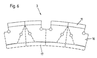
- the solution to this problem is according to the invention characterized in that the permanent magnets as air gap magnets trained on U-shaped, sheet metal or solid Yokes are arranged in sections on a rotor tube are attached on top.
- the Permanent magnets arranged as a flux concentration arrangement.
- the permanent magnets are arranged surrounded by a laminated core.
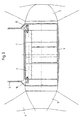
- the drive devices according to the figures Fig. 1 to Fig. 3 consist of a streamlined designed, the Form of a nacelle housing 1 with an arranged therein synchronous motor consisting of stator 2 and rotor 3 and a shaft 4, via which the drive device on Bottom of a ship's hull, not shown, in the form of a gondola is attached.
- the housing 1 has - as can be seen from FIGS. 1 and 2 - End caps 5 and 6 on the bearing 7 of a drive shaft 8. While in the embodiment according to the figures 1 and 2 only at one end of the drive shaft 8 a propeller 9 is arranged in the embodiment according to Fig. 3 arranged at both ends of the drive shaft 8 propeller 9.
- stator 2 of the Synchronous motor non-positively in the hollow cylindrical housing 1 fitted.
- this frictional connection by shrinking the housing part on the laminated core of the stator 2, due to the seat is stacked several times.
- the Windings of the stator 2 are shown in Figures 1 to Fig. 3 partially shown with the winding heads 10.
- the Rotor 3 of the synchronous motor is in a manner known per se designed as a rotor 3 provided with permanent magnets 11 and rests on the drive shaft by means of a support structure 12 8th.
- the synchronous motor is cooled by the non-positive and / or positive connection between stator 2 and Housing 1 such that the housing 1 is designed as an outer wall cooler is.
- the synchronous motor is thus cooled through the water surrounding or flowing around the housing 1, without additional cooling media through in the stator 2 or between Stator 2 and housing 1 provided cooling channels need to be known from the prior art is.
- 1 is one first embodiment for such an additional cooling device shown for cooling the winding heads 10 of the stator 2.
- this first embodiment is within the Winding heads 10, that is, in the radial direction between the Winding heads 10 of each end face of the stator 2, on the Drive shaft 8 each have a fan 13 arranged. With help this fan 13 becomes the one located in the interior of the synchronous motor Air is convectively circulated and flows around the end windings 10. The heat absorbed by the swirling air the air is formed via the external wall cooler Housing 1 withdrawn by the water flowing around the housing 1.
- FIG. 2 is a second embodiment for forming the additional cooling device shown.
- this embodiment is for cooling the winding heads 10 of the stator 2 at the end of the winding heads 10, each in cross section tubular ring 14 arranged in the direction of the winding heads 10 is provided with spray openings.
- Spray openings can be sprayed insulating oil that is located as an oil sump 15 below the drive shaft 8 and from there in each case by means of an arranged outside the housing 1 Pump is pumped into the ring 14.
- the one in the oil swamp 15 insulating oil is also the heat the housing 1 formed as an outer wall cooler by the Extracted from housing 1 flowing water.
- both cooling devices to cool the winding heads 10 of the stator 2 to combine, so that the cooling of the winding heads 10 both via the fans 13 and the ring 14 sprayed insulating oil.
- the oil sump 15 in the housing 1 make sure that the Insulating oil level does not rise so far that insulating oil in the Air gap between stator 2 and rotor 3 of the synchronous motor arrives, as this significantly increases the efficiency of the engine would be affected.
- the housing 1 can have a relatively small outer diameter D. G , so that the ratio between the outer diameter D G of the housing 1 and the outer diameter D p of the propeller 9 reaches a relatively small value of, for example, 0.35, even if the synchronous motor for a drive power of up to 20 MW and more is designed.
- This configuration of the housing 1 of the electric ship propulsion as an outside wall cooler is independent of whether that nacelle-like housing 1 on the hull rigid or rotatable is. It is particularly advantageous for maneuvering however, if the gondola-like housing 1 about the longitudinal axis of the Shaft 4 is rotatable, so that this drive also for rudderless Ships is suitable.
- the permanent magnets 11 are air gap magnets trained on a U-shaped, sheeted or massive yoke 16 are arranged.
Landscapes
- Engineering & Computer Science (AREA)
- Power Engineering (AREA)
- Chemical & Material Sciences (AREA)
- Combustion & Propulsion (AREA)
- Mechanical Engineering (AREA)
- Ocean & Marine Engineering (AREA)
- Motor Or Generator Cooling System (AREA)
- Permanent Magnet Type Synchronous Machine (AREA)
- Motor Or Generator Frames (AREA)
Description
- Fig. 1
- einen Längsschnitt durch eine erfindungsgemäße Antriebseinrichtung mit Luftkühlung der Wickelköpfe des Stators;
- Fig. 2
- einen Längsschnitt durch eine erfindungsgemäße Antriebseinrichtung mit Sprühkühlung der Wickelköpfe des Stators;
- Fig. 3
- einen Längsschnitt durch eine erfindungsgemäße Antriebseinrichtung, bei der der Stator des Motors mit dem Gehäuse kraftschlüssig durch eine Schrumpfverbindung verbunden ist;
- Fig. 4
- eine ausschnittsweise Darstellung einer ersten Ausführungsform zur Anordnung von Permanentmagneten und Joch;
- Fig. 5
- eine ausschnittsweise Darstellung einer zweiten Ausführungsform zur Anordnung von Permanentmagneten und Joch und
- Fig. 6
- eine ausschnittsweise Darstellung einer dritten Ausführungsform zur Anordnung von Permanentmagneten und Joch.
Claims (3)
- Elektrische Antriebseinrichtung für Schiffe, bestehend aus einem an der Unterseite des Schiffsrumpfes gondelartig angeordneten Gehäuse (1) zur Aufnahme eines Elektromotors mit Läufer (3) und Stator (2), wobei an der den Läufer (3) tragenden Welle (8) wenigstens ein Propeller (9) angeordnet ist, wobei der elektrische Motor als Synchronmotor ausgebildet ist, und wobei der Läufer (3) Permanentmagnete (11) zur Erregung des Stators (2) aufweist und daß das Gehäuse (1) als Außenwandkühler ausgebildet ist, dadurch gekennzeichnet, daß die Permanentmagnete (11) als Luftspaltmagnete ausgebildet auf U-förmigen, geblechten oder massiven Jochen (16) angeordnet sind, die auf einem Läuferrohr (11,17) abschnittsweise aufliegend befestigt sind.
- Elektrische Antriebseinrichtung nach Anspruch 1, dadurch gekennzeichnet, daß die Permanentmagnete (11) als Flußkonzentrationsanordnung angeordnet sind.
- Elektrische Antriebseinrichtung nach Anspruch 1 oder 2, dadurch gekennzeichnet, daß die Permanentmagnete (11) von einem Blechpaket umschlossen angeordnet sind.
Applications Claiming Priority (3)
| Application Number | Priority Date | Filing Date | Title |
|---|---|---|---|
| DE1998101448 DE19801448C2 (de) | 1998-01-16 | 1998-01-16 | Elektrische Antriebseinrichtung für Schiffe |
| DE19801448 | 1998-01-16 | ||
| PCT/DE1998/003770 WO1999036312A2 (de) | 1998-01-16 | 1998-12-22 | Elektrische antriebseinrichtung für schiffe |
Publications (2)
| Publication Number | Publication Date |
|---|---|
| EP1047592A2 EP1047592A2 (de) | 2000-11-02 |
| EP1047592B1 true EP1047592B1 (de) | 2002-09-18 |
Family
ID=7854796
Family Applications (1)
| Application Number | Title | Priority Date | Filing Date |
|---|---|---|---|
| EP98966573A Expired - Lifetime EP1047592B1 (de) | 1998-01-16 | 1998-12-22 | Elektrische antriebseinrichtung für schiffe |
Country Status (5)
| Country | Link |
|---|---|
| EP (1) | EP1047592B1 (de) |
| AU (1) | AU2410499A (de) |
| DK (1) | DK1047592T3 (de) |
| ES (1) | ES2184356T3 (de) |
| WO (1) | WO1999036312A2 (de) |
Cited By (2)
| Publication number | Priority date | Publication date | Assignee | Title |
|---|---|---|---|---|
| DE102010010395A1 (de) * | 2010-03-05 | 2011-06-16 | Siemens Aktiengesellschaft | Permanentmagneterregte Maschine mit Innenkühlkreislauf |
| US12459624B1 (en) | 2023-04-20 | 2025-11-04 | Brunswick Corporation | Marine drives having an electric motor assembly and methods for making the same |
Families Citing this family (10)
| Publication number | Priority date | Publication date | Assignee | Title |
|---|---|---|---|---|
| JP2003506998A (ja) * | 1999-08-03 | 2003-02-18 | シーメンス アクチエンゲゼルシヤフト | 減磁防護形永久磁石励磁式船舶推進装置 |
| FI115042B (fi) | 2000-01-28 | 2005-02-28 | Abb Oy | Aluksen moottoriyksikkö |
| FR2815485B1 (fr) | 2000-10-12 | 2003-01-24 | France Etat Armement | Dispositif de reduction du bruit et d'absorption des vibrations generees par un moteur electrique integre dans une nacelle de propulsion d'un navire |
| DE10058293A1 (de) | 2000-11-23 | 2002-05-29 | Siemens Ag | Aktive Geräuschkompensation |
| DE10322275A1 (de) * | 2003-05-16 | 2004-12-02 | Siemens Ag | Kühlsystem für Elektrisches Antriebssystem mit Synchronmaschine mit Hochtemperatur-Supraleitender Feldwicklung für Propeller- und Jetantrieb mit besonders kleinen Durchmessern in schwimmenden Geräten |
| US7213811B2 (en) | 2004-12-08 | 2007-05-08 | Scientific Games Royalty Corporation | Extension to a lottery game for which winning indicia are set by selections made by winners of a base lottery game |
| DE102008046292A1 (de) | 2008-09-08 | 2010-03-18 | Siemens Aktiengesellschaft | Schiffsantrieb für ein Wasserfahrzeug |
| TWI402201B (zh) * | 2011-04-01 | 2013-07-21 | Chieng Ming Ind Co Ltd | Underwater propeller |
| ES2397582B1 (es) | 2012-01-13 | 2014-03-11 | Empresa Naviera Elcano, S.A. | Procedimiento de transformación de buques metaneros propulsados por turbinas de vapor |
| RU2525838C2 (ru) * | 2012-05-21 | 2014-08-20 | Маджара Дмитрий Михайлович | Узел движителя с электрическим двигателем и его аэродинамический движитель |
Family Cites Families (14)
| Publication number | Priority date | Publication date | Assignee | Title |
|---|---|---|---|---|
| US2714866A (en) | 1951-02-19 | 1955-08-09 | Friedrich W Pleuger | Device for propelling a ship |
| US2862122A (en) | 1955-03-14 | 1958-11-25 | Westinghouse Electric Corp | Submersible dynamoelectric machine |
| JPS5942547B2 (ja) * | 1978-11-29 | 1984-10-16 | 株式会社日立製作所 | 回転電機のブラシ保持装置 |
| FR2471682A1 (fr) * | 1979-12-12 | 1981-06-19 | Sacre Louis | Perfectionnement aux collecteurs tournants a axe vertical |
| JPS5975161A (ja) * | 1982-10-22 | 1984-04-27 | Mitsubishi Electric Corp | スリツプリング検査装置 |
| JPS6194548A (ja) * | 1984-10-16 | 1986-05-13 | Fanuc Ltd | 永久磁石回転子 |
| DE4030619A1 (de) * | 1990-09-27 | 1992-04-02 | Siemens Ag | Mehrphasige permanentmagneterregte elektrische maschine synchroner bauart |
| JPH05300724A (ja) * | 1991-03-20 | 1993-11-12 | Yaskawa Electric Corp | 電磁ブレーキ |
| JPH0663034A (ja) * | 1992-08-21 | 1994-03-08 | Toshiba Corp | X線断層像撮影装置 |
| FI96590C (fi) | 1992-09-28 | 2003-11-27 | Abb Oy | Laivan propulsiolaite |
| JP2691495B2 (ja) * | 1992-10-12 | 1997-12-17 | 財団法人鉄道総合技術研究所 | スリップリング支持装置 |
| CN1106584A (zh) * | 1994-10-31 | 1995-08-09 | 白侠斌 | 新结构发电机 |
| DE19519424C2 (de) * | 1995-05-26 | 1997-05-22 | Stn Atlas Elektronik Gmbh | Stromrichterantrieb |
| DE19627323A1 (de) * | 1996-06-26 | 1998-01-02 | Siemens Ag | Gondelartig anzuordnender Schiffsantrieb mit Synchronmotor |
-
1998
- 1998-12-22 WO PCT/DE1998/003770 patent/WO1999036312A2/de not_active Ceased
- 1998-12-22 AU AU24104/99A patent/AU2410499A/en not_active Abandoned
- 1998-12-22 ES ES98966573T patent/ES2184356T3/es not_active Expired - Lifetime
- 1998-12-22 DK DK98966573T patent/DK1047592T3/da active
- 1998-12-22 EP EP98966573A patent/EP1047592B1/de not_active Expired - Lifetime
Cited By (2)
| Publication number | Priority date | Publication date | Assignee | Title |
|---|---|---|---|---|
| DE102010010395A1 (de) * | 2010-03-05 | 2011-06-16 | Siemens Aktiengesellschaft | Permanentmagneterregte Maschine mit Innenkühlkreislauf |
| US12459624B1 (en) | 2023-04-20 | 2025-11-04 | Brunswick Corporation | Marine drives having an electric motor assembly and methods for making the same |
Also Published As
| Publication number | Publication date |
|---|---|
| EP1047592A2 (de) | 2000-11-02 |
| WO1999036312A2 (de) | 1999-07-22 |
| DK1047592T3 (da) | 2003-01-27 |
| AU2410499A (en) | 1999-08-02 |
| ES2184356T3 (es) | 2003-04-01 |
| WO1999036312A3 (de) | 1999-11-11 |
Similar Documents
| Publication | Publication Date | Title |
|---|---|---|
| EP0907556B1 (de) | Gondelartig anzuordnender schiffsantrieb mit synchronmotor | |
| DE19780317B4 (de) | Elektrische Maschine | |
| DE60201937T2 (de) | Elektrische Maschine mit äusserem Läufer | |
| EP0996567B1 (de) | Elektromotorischer gondel-schiffsantrieb mit kühleinrichtung | |
| WO2005027321A1 (de) | Dreiphasige synchronmaschine mit permanentmagnetläufer mit induktionskäfig | |
| DE102020129142B4 (de) | Läufer für eine rotierende elektrische Maschine | |
| EP2319159A2 (de) | Rotor einer elektrische maschine | |
| EP2030305A1 (de) | Wechselstromgenerator für kraftfahrzeuge | |
| EP1362404A1 (de) | Elektrische maschine | |
| DE102021131448A1 (de) | Kühlvorrichtung für einen Stator mit Kühlmantel außerhalb eines Innengehäuseteils | |
| DE102022213027A1 (de) | Rotor und elektrische Maschine | |
| EP1047592A2 (de) | Elektrische antriebseinrichtung für schiffe | |
| EP3451507A1 (de) | Elektrische rotierende maschine für einen gondelantrieb | |
| EP2319164B1 (de) | Rotor für eine elektrische maschine mit reduziertem rastmoment | |
| DE19801448C2 (de) | Elektrische Antriebseinrichtung für Schiffe | |
| DE102019205153A1 (de) | Statorzahn mit asymmetrischer Zahngeometrie | |
| EP1524751A1 (de) | Elektromotor und Verfahren zur Herstellung | |
| DE2646550B2 (de) | Asynchronmaschine | |
| WO2011104265A2 (de) | Elektrische maschine mit rotoreinrichtung und rotoreinrichtung mit optimiertem magnetfluss und verfahren zum betreiben der elektrischen maschine | |
| DE102011116398A1 (de) | Anlasser | |
| DE102024207555A1 (de) | Rotor für eine Asynchronmaschine mit asymmetrisch zugeordneter Führungsöffnung, Asynchronmaschine sowie Fahrzeug | |
| DE102021120652A1 (de) | Elektromotor für ein Kraftfahrzeug, Rotor für einen Elektromotor und Kraftfahrzeug mit einem Elektromotor | |
| DE3685825T2 (de) | Wechselstromgeneratoranordnung. | |
| DE102022129626A1 (de) | Stator | |
| DE102022106556A1 (de) | Elektrische Maschine |
Legal Events
| Date | Code | Title | Description |
|---|---|---|---|
| PUAI | Public reference made under article 153(3) epc to a published international application that has entered the european phase |
Free format text: ORIGINAL CODE: 0009012 |
|
| 17P | Request for examination filed |
Effective date: 20000417 |
|
| AK | Designated contracting states |
Kind code of ref document: A2 Designated state(s): DE DK ES FI FR GB IT NL SE |
|
| 17Q | First examination report despatched |
Effective date: 20010508 |
|
| GRAG | Despatch of communication of intention to grant |
Free format text: ORIGINAL CODE: EPIDOS AGRA |
|
| GRAG | Despatch of communication of intention to grant |
Free format text: ORIGINAL CODE: EPIDOS AGRA |
|
| GRAH | Despatch of communication of intention to grant a patent |
Free format text: ORIGINAL CODE: EPIDOS IGRA |
|
| GRAH | Despatch of communication of intention to grant a patent |
Free format text: ORIGINAL CODE: EPIDOS IGRA |
|
| GRAA | (expected) grant |
Free format text: ORIGINAL CODE: 0009210 |
|
| AK | Designated contracting states |
Kind code of ref document: B1 Designated state(s): DE DK ES FI FR GB IT NL SE |
|
| REG | Reference to a national code |
Ref country code: GB Ref legal event code: FG4D Free format text: NOT ENGLISH |
|
| REF | Corresponds to: |
Ref document number: 59805648 Country of ref document: DE Date of ref document: 20021024 |
|
| GBT | Gb: translation of ep patent filed (gb section 77(6)(a)/1977) |
Effective date: 20021108 |
|
| REG | Reference to a national code |
Ref country code: DK Ref legal event code: T3 |
|
| ET | Fr: translation filed | ||
| REG | Reference to a national code |
Ref country code: ES Ref legal event code: FG2A Ref document number: 2184356 Country of ref document: ES Kind code of ref document: T3 |
|
| PLBE | No opposition filed within time limit |
Free format text: ORIGINAL CODE: 0009261 |
|
| STAA | Information on the status of an ep patent application or granted ep patent |
Free format text: STATUS: NO OPPOSITION FILED WITHIN TIME LIMIT |
|
| 26N | No opposition filed |
Effective date: 20030619 |
|
| PGFP | Annual fee paid to national office [announced via postgrant information from national office to epo] |
Ref country code: DK Payment date: 20081211 Year of fee payment: 11 |
|
| PGFP | Annual fee paid to national office [announced via postgrant information from national office to epo] |
Ref country code: SE Payment date: 20090116 Year of fee payment: 11 |
|
| EUG | Se: european patent has lapsed | ||
| REG | Reference to a national code |
Ref country code: DK Ref legal event code: EBP |
|
| PG25 | Lapsed in a contracting state [announced via postgrant information from national office to epo] |
Ref country code: DK Free format text: LAPSE BECAUSE OF NON-PAYMENT OF DUE FEES Effective date: 20100104 |
|
| PG25 | Lapsed in a contracting state [announced via postgrant information from national office to epo] |
Ref country code: SE Free format text: LAPSE BECAUSE OF NON-PAYMENT OF DUE FEES Effective date: 20091223 |
|
| PGFP | Annual fee paid to national office [announced via postgrant information from national office to epo] |
Ref country code: FI Payment date: 20141211 Year of fee payment: 17 Ref country code: GB Payment date: 20141208 Year of fee payment: 17 |
|
| PGFP | Annual fee paid to national office [announced via postgrant information from national office to epo] |
Ref country code: NL Payment date: 20141203 Year of fee payment: 17 |
|
| PGFP | Annual fee paid to national office [announced via postgrant information from national office to epo] |
Ref country code: IT Payment date: 20141219 Year of fee payment: 17 |
|
| PGFP | Annual fee paid to national office [announced via postgrant information from national office to epo] |
Ref country code: ES Payment date: 20150127 Year of fee payment: 17 Ref country code: DE Payment date: 20150220 Year of fee payment: 17 |
|
| PGFP | Annual fee paid to national office [announced via postgrant information from national office to epo] |
Ref country code: FR Payment date: 20141217 Year of fee payment: 17 |
|
| REG | Reference to a national code |
Ref country code: DE Ref legal event code: R119 Ref document number: 59805648 Country of ref document: DE |
|
| GBPC | Gb: european patent ceased through non-payment of renewal fee |
Effective date: 20151222 |
|
| REG | Reference to a national code |
Ref country code: NL Ref legal event code: MM Effective date: 20160101 |
|
| REG | Reference to a national code |
Ref country code: FR Ref legal event code: ST Effective date: 20160831 |
|
| PG25 | Lapsed in a contracting state [announced via postgrant information from national office to epo] |
Ref country code: NL Free format text: LAPSE BECAUSE OF NON-PAYMENT OF DUE FEES Effective date: 20160101 Ref country code: DE Free format text: LAPSE BECAUSE OF NON-PAYMENT OF DUE FEES Effective date: 20160701 Ref country code: GB Free format text: LAPSE BECAUSE OF NON-PAYMENT OF DUE FEES Effective date: 20151222 |
|
| PG25 | Lapsed in a contracting state [announced via postgrant information from national office to epo] |
Ref country code: FR Free format text: LAPSE BECAUSE OF NON-PAYMENT OF DUE FEES Effective date: 20151231 |
|
| PG25 | Lapsed in a contracting state [announced via postgrant information from national office to epo] |
Ref country code: IT Free format text: LAPSE BECAUSE OF NON-PAYMENT OF DUE FEES Effective date: 20151222 |
|
| REG | Reference to a national code |
Ref country code: ES Ref legal event code: FD2A Effective date: 20170127 |
|
| PG25 | Lapsed in a contracting state [announced via postgrant information from national office to epo] |
Ref country code: ES Free format text: LAPSE BECAUSE OF NON-PAYMENT OF DUE FEES Effective date: 20151223 |
|
| PG25 | Lapsed in a contracting state [announced via postgrant information from national office to epo] |
Ref country code: FI Free format text: LAPSE BECAUSE OF NON-PAYMENT OF DUE FEES Effective date: 20151222 |