EP1047173A2 - Verfahren zur Erzeugung von Daten zur Überwachung und Regelung des Lade- und Entladezustandes einer Sekundärbatterie - Google Patents
Verfahren zur Erzeugung von Daten zur Überwachung und Regelung des Lade- und Entladezustandes einer Sekundärbatterie Download PDFInfo
- Publication number
- EP1047173A2 EP1047173A2 EP00302336A EP00302336A EP1047173A2 EP 1047173 A2 EP1047173 A2 EP 1047173A2 EP 00302336 A EP00302336 A EP 00302336A EP 00302336 A EP00302336 A EP 00302336A EP 1047173 A2 EP1047173 A2 EP 1047173A2
- Authority
- EP
- European Patent Office
- Prior art keywords
- voltage value
- discharge
- full
- secondary battery
- charge capacity
- Prior art date
- Legal status (The legal status is an assumption and is not a legal conclusion. Google has not performed a legal analysis and makes no representation as to the accuracy of the status listed.)
- Granted
Links
Images


Classifications
-
- H—ELECTRICITY
- H01—ELECTRIC ELEMENTS
- H01M—PROCESSES OR MEANS, e.g. BATTERIES, FOR THE DIRECT CONVERSION OF CHEMICAL ENERGY INTO ELECTRICAL ENERGY
- H01M10/00—Secondary cells; Manufacture thereof
- H01M10/42—Methods or arrangements for servicing or maintenance of secondary cells or secondary half-cells
-
- H—ELECTRICITY
- H01—ELECTRIC ELEMENTS
- H01M—PROCESSES OR MEANS, e.g. BATTERIES, FOR THE DIRECT CONVERSION OF CHEMICAL ENERGY INTO ELECTRICAL ENERGY
- H01M10/00—Secondary cells; Manufacture thereof
- H01M10/42—Methods or arrangements for servicing or maintenance of secondary cells or secondary half-cells
- H01M10/425—Structural combination with electronic components, e.g. electronic circuits integrated to the outside of the casing
- H01M10/4257—Smart batteries, e.g. electronic circuits inside the housing of the cells or batteries
-
- H—ELECTRICITY
- H02—GENERATION; CONVERSION OR DISTRIBUTION OF ELECTRIC POWER
- H02J—ELECTRIC POWER NETWORKS; CIRCUIT ARRANGEMENTS OR SYSTEMS FOR SUPPLYING OR DISTRIBUTING ELECTRIC POWER; SYSTEMS FOR STORING ELECTRIC ENERGY
- H02J7/00—Circuit arrangements for charging or discharging batteries or for supplying loads from batteries
-
- H—ELECTRICITY
- H02—GENERATION; CONVERSION OR DISTRIBUTION OF ELECTRIC POWER
- H02J—ELECTRIC POWER NETWORKS; CIRCUIT ARRANGEMENTS OR SYSTEMS FOR SUPPLYING OR DISTRIBUTING ELECTRIC POWER; SYSTEMS FOR STORING ELECTRIC ENERGY
- H02J7/00—Circuit arrangements for charging or discharging batteries or for supplying loads from batteries
- H02J7/60—Circuit arrangements for charging or discharging batteries or for supplying loads from batteries including safety or protection arrangements
- H02J7/685—Circuit arrangements for charging or discharging batteries or for supplying loads from batteries including safety or protection arrangements using connection detecting circuits
-
- Y—GENERAL TAGGING OF NEW TECHNOLOGICAL DEVELOPMENTS; GENERAL TAGGING OF CROSS-SECTIONAL TECHNOLOGIES SPANNING OVER SEVERAL SECTIONS OF THE IPC; TECHNICAL SUBJECTS COVERED BY FORMER USPC CROSS-REFERENCE ART COLLECTIONS [XRACs] AND DIGESTS
- Y02—TECHNOLOGIES OR APPLICATIONS FOR MITIGATION OR ADAPTATION AGAINST CLIMATE CHANGE
- Y02E—REDUCTION OF GREENHOUSE GAS [GHG] EMISSIONS, RELATED TO ENERGY GENERATION, TRANSMISSION OR DISTRIBUTION
- Y02E60/00—Enabling technologies; Technologies with a potential or indirect contribution to GHG emissions mitigation
- Y02E60/10—Energy storage using batteries
Definitions
- the present invention relates to a method of generating data for use in monitoring and controlling the charge and discharge statuses of a secondary battery, and more particularly, to a method of generating data, which is generated by a microcomputer installed in a secondary battery pack and is transferred to an external device.
- secondary battery packs have adopted a microcomputer and a peripheral circuit for generating data used to monitor and control the charge and discharge statuses thereof.
- the reference full-charge capacity of the secondary battery is periodically updated through a learning process performed during a charge mode of the secondary battery. That is, the conventional algorithm calculates a real full-charge capacity, which is proportional to the rate of charging of the secondary battery, and designates the calculated real full-charge capacity as a reference full-charge capacity.
- the algorithm performed by a microcomputer installed in the conventional secondary battery pack cannot be considered as a good algorithm which well reflects the operating properties of secondary batteries.
- the degree of accuracy in data associated with the reference full-charge capacity is lowered.
- the conventional algorithm determines the charging voltage value using only a read instantaneous voltage value, thereby further lowering the accuracy of data.
- a method of generating data for use in monitoring and controlling the charge and discharge statuses of a secondary battery which is performed by a microcomputer installed in a secondary battery pack, the method comprising the steps of: (S1) periodically calculating and updating the average voltage value of the secondary battery; (S2) executing a charge mode, a discharge mode, a self-discharge mode according to the amplitude and sign of an instantaneous current value flowing through the secondary battery; (S3) when the discharge mode starts, periodically cumulating a discharge capacity and updating a required full charge capacity for the present period of time with the cumulation result; and (S4) if the average voltage value for the present period of time drops below the lower limit of the frill discharge voltage value during the step (S3), updating the reference full charge capacity with the required full charge capacity for the present period of time.
- the reference full charge capacity is updated with the required full charge capacity obtained in a discharge mode. That is, the discharging properties of the secondary battery, which in contrast to the charging properties sharply change with time, are reflected in the reference full charge capacity, so that the charge and discharge statuses of the secondary battery can be monitored and controlled with accurate data. Also, the charge status of the secondary battery is determined using the average voltage value of the secondary cell, and thus more accurate data can be generated.
- the secondary battery pack 1 includes a secondary battery 11, field effect transistors (FETs) 12, a peripheral circuit 13, a resistor 14, a protection element 15, a microcomputer 16, an electrically erasable and programmable read only memory (EEPROM) 17, and a thermistor 18.
- FETs 12 are turned on or off in response to a control signal from the peripheral circuit 13, and control the charge and discharge statuses of the secondary battery 11.
- the peripheral circuit 13 measures an instantaneous voltage of the secondary battery 11, and an instantaneous current of the secondary battery 11 by measuring the current flowing through the resistor 14. Also, the peripheral circuit 13 turns the FETs 12 on or off according to a control signal from the microcomputer 16.
- the protection element 15 is for preventing over charging and over discharging, which may occur when the FETs 12 do not operate normally.
- the microcomputer 16 which performs the algorithm according to the present invention, receives the instantaneous voltage and the instantaneous current from the peripheral circuit 13 and a surrounding temperature from the thermistor 18, and generates data for use in monitoring and controlling the charge and discharge statuses of the secondary battery 11.
- the status controlling data is transferred to the peripheral circuit 13 and the status monitoring data is transferred too a notebook computer through serial communications lines.
- reference character SMCLK represents a clock signal
- reference character SMDT represents a data signal.
- FIG. 2 shows the primary algorithm of the microcomputer 16 shown in FIG. 1 according to a preferred embodiment of the present invention.
- a step of continuously calculating and updating an average voltage value "avadvol” of the secondary battery 11 (see FIG. 1) for a predetermined period of time is incorporated. Since the charge status is determined using the average voltage value "avadvol", more accurate data can be obtained.
- status registers and status bits in the microcomputer 16 are initialized in step 201. Then, according to the amplitude and sign of an instantaneous current value "adcur" flowing through the secondary cell 11, a charge mode, a discharge mode or a self-discharge mode, is performed (steps 202 through 210). Then, the steps 202 and 210 are iterated.
- the instantaneous current value "adcur” is received (step 202). If the instantaneous current value "adcur” is greater than or equal to 0, a charge/discharge information bit "f_ampn” is set to 1. Otherwise, the charge/discharge information bit “f_ampn” is set to 0 (steps 203 through 205). Then, it is determined whether the instantaneous current value "adcur” is less than or equal to 10 (step 206). If the instantaneous current value "adcur” is less than or equal to 10, the self-discharge mode is carried out (step 207). Otherwise, a determination is made as to whether the charge/discharge information bit "f_ampn” is equal to 1 (step 208).
- step 209 If the charge/discharge information bit "f_ampn" is equal to 1, the charge mode is carried out (step 209). However, if the charge/discharge information bit "f_ampn” is not equal to 1, the discharge mode is carried out (step 210).
- FIG. 3 illustrates the execution program for the discharge mode, corresponding to the step 210 of FIG. 2, according to the present invention.
- the execution program for the discharge mode includes calculating a discharge efficiency "dis_eff" (steps 304 and 305), calculating a discharge capacity "DCR” (a sub-step of step 307), updating a required full charge capacity “s_dcr” (step 307) and updating a reference full charge capacity "f_c_capac” (step 322).
- the discharge efficiency "dis_eff" at the present temperature “adtemp" of the secondary battery 11 is calculated.
- the discharge capacity "DCR” is calculated as the product of the instantaneous current value “adcur”, a period of time “ ⁇ t” from a discharging point to the present time and the discharge efficiency "dis_eff".
- the discharge capacity "DCR” is added to the required full charge capacity "s_dcr" determined in the preceding period of time.
- the required full charge capacity "s_dcr" for the present period of time is updated with the sum result.
- step 322 of updating the reference full charge capacity "f_c_capac” if the avenge voltage "adadvol” of the secondary battery 11 for the present period of time is lower than a lower limit of the full discharge voltage value "s_edv0", the reference full charge capacity "f_c_capac” for the present period of time is updated to be equal to the required full charge capacity "s_dcr" for the present period of time, using a capacity learning program.
- the reference full charge capacity "f_c_capac" is updated to be equal to the required full charge capacity "s_dcr" which is calculated during the discharge mode. That is, the discharging properties, which change rapidly over time, are considered in setting the reference full charge capacity "f_c_capac", so that the charge and discharge statuses of the secondary battery 11 can be accurately monitored and controlled with the data.
- the step 301 sets the discharge information bit "f_dischg” to 1, to indicate the discharge mode. Then, an average current value “avr_cur” flowing through the secondary battery 11 for a given period of time is calculated (step 302). Then, the present current value “adcur” is divided by a designated rated charge capacity "design_capac", resulting in a discharge rate "d_crate” (step 303). The present temperature “atemp” is read (step 304), and the discharge efficiency "dis_eff" at the read present temperature “atemp” is calculated (step 305). If the average voltage value "adadvol” is less than or equal to the lower limit of the full discharge voltage value "s_edv0" (step 306), the process moves to the step 310.
- the calculated discharge capacity DCT is added to the required full charge capacity "s_dcr", which is determined in the preceding period, and the required full charge capacity "s_dcr" for the present period of time is updated with the sum result.
- the discharge capacity "DCR” is subtracted from the real charge capacity “RRC” for the preceding period of time, and the rear charge capacity “RRC” for the present period of time is updated with the subtraction result.
- the rear charge capacity "RRC” for the present period is added to a designated disuse capacity "s_bla_c", and an estimated charge capacity "rc_capaa” for the present period is updated with the sum result.
- the estimated charge capacity "rc_capaa” is divided by the full charge capacity "f_c_capac", and then a relative charge rate “re_st_ch” is updated with the result. Then, the estimated charge capacity “rc_capaa” is divided by the designated charge capacity “design_capac”, and an absolute charge rate “ad_st_ch” is updated with the result (step 311).
- the estimated charge capacity "rc_capaa” is divided by the read instantaneous current value "adcur” and a required time for being fully discharged (hereinafter, simply referred to as a required full discharge time) "r_t_empc” is updated with the result (step 312). Also, the estimated charge capacity "rc_capaa” is divided by the average current value "avr_cur”, and a total charging time “aver_t_ea” is updated with the result (step 313).
- an estimated charge capacity "rc_capaa” is less than or equal to an alarm charge capacity "r_c_ac"
- a user is alerted that the charge capacity is very low (steps 314 and 315).
- an estimated full discharge time is shorter than or equal to a lower limit of the full discharge time "r_t_a”, the user is alerted that it is near full (steps 317 through 319).
- step 320 it is determined whether to execute the capacity learning program using a maximum full charge bit "f_fullchg0" (step 320).
- the maximum full charge bit "f_fullchg0" is set to 1 if the voltage level has once reached a maximum full charge voltage, and the maximum full charge bit "f_fullchg0" is updated with 0 after the step 322 of running the capacity learning program.
- a logic value of the maximum full charge bit "f_fullchg0" is 0, which indicates that the capacity learning program has been performed, there is no need to run the capacity learning program as long as the system is reinitialized, for example, the power is turned off.
- step 231 it is determined whether the average voltage value "avadvol1" is higher than or equal to a second full discharge voltage value "s_edv2" (step 231).
- the second full discharge voltage value "s_edv2" is set so as to determined whether to execute the capacity learning program (step 322). Referring to FIG.
- three full discharge voltage values are used, including the lower limit of the full discharge voltage value "s_edv0", the first full discharge voltage value "s_edv1”, which is higher than the lower limit of the full discharge voltage value "s_edv0", and the second full discharge voltage value "s_edv2", which is higher than the first full discharge voltage value "s_edv1 ".
- the reason for using three full discharge voltage values is to monitor the average voltage value of the secondary battery 11 (see FIG.
- FIG. 5 illustrates the capacity learning program (step 322) of FIG. 3.
- a first capacity learning stage from step 501 to step 508, is performed when the average voltage value "avadvol” of the secondary battery 11 (see FIG. 1) is lower than the second full discharge voltage value "s_edv2" and is higher than or equal to the first full discharge voltage value "s_edv1".
- a second capacity learning stage from step 511 to step 521, is performed when the average voltage value "adadvol” of the secondary battery is lower than the first full discharge voltage value "s_edv1" and is higher than or equal to the lower limit of the full discharge voltage value "s_edv0".
- a final capacity learning stage from step 531 to step 540, is performed when the average voltage value "adadvol” of the secondary battery 11 is lower than the lower limit of the full discharge voltage value "s_edv0".
- the average voltage value "adadvol” is compared to the first full discharge voltage value "s_edv1" (step 501). If the average voltage value "adadvol” is lower than the first full discharge voltage value "s_edv1”, the process moves to the step 511. If the average voltage value "adadvol” is higher than or equal to the first full discharge voltage value "s_edv1", the logic state of a second full charge bit "f_fullchg2" is checked (step 502). If the logic value of the second full charge bit "f_fullchg2" is 1, step 503 is performed. Otherwise, the process retains to the step 202.
- the second full charge bit "f_fullchg2" is set to "1".
- the first capacity learning stage from the steps 501 to 508
- the second full charge bit "f_fullchg2" is updated with "0".
- the logic value of the second full charge bit "f_fullchg2" is 0, there is no need to perform the first capacity learning stage as long as the system is reinitialized, for example, the power is turned off.
- step 503 the logic stage of the second full discharge bit "f_edv2" is checked. If the logic value of the second full discharge bit "f_edv2" is equal to "1", the step 504 is performed. Otherwise, the process returns to the step 202.
- the second full discharge bit "f_edv2" is updated with "0" when the first capacity learning stage has been performed after the system is initialized (step 504).
- An approximate lifetime value "ccount” is incremented by 0.2 (step 505). In other words, since the avenge voltage value "adadvol” of the secondary battery 11 (see FIG. 1) enters the range between the second full discharge voltage value "s_edv1" and the first full discharge voltage value "s_edv1 ", the remaining lifetime is updated taking into account the level of decreased capacity, which corresponds to the average voltage value "adadvol".
- the first full discharge bit "f_edv1" is updated with 1 (step 506), and a preliminary compensation routine (step 507) is executed.
- the preliminary compensation routine (step 507) is the same as the other preliminary compensation routine (step 520) of the second capacity learning stages (steps 511 to 521), but it is different from a final compensation routine (step 539) of the final capacity learning stages (steps 530 to 540).
- the logic value of a second compensation bit "f_count2" is updated with "1” and the logic value of the second full charge bit "f_fullchg2" is updated with "0" (step 508), and then the process returns to the step 202 of FIG. 2.
- step 511 the average voltage value "avadvol” is compared to the lower limit of the full discharge voltage value "s_edv0" (step 511). If the average voltage value "adadvol” is lower than the lower limit of the full discharge voltage value "s_edv0”, the process moves to the step 531. If the average voltage value :adadvol” is higher than or equal too the lower limit of the full discharge voltage value "s_edv0", the logic state of a first full change bit "f_fullchg1" is checked (step 512). If the logic value of the first full charge bit "f_fullchg1" is 1, step 514 is performed. Otherwise, the process moves to the step 202.
- the first full charge bit "f_fullchg1" is set to "1".
- the second capacity learning stage from the steps 511 to 521) has been performed after the system is initialized, the first full charge bit "f_fullchg1" is updated with "0".
- the logic value of the first full charge bit "f_fullchg1" is 0, there is no need to perform the second capacity learning stage as long as the system is reinitialized, for example, the power is turned off.
- step 513 the logic state of the first full discharge bit "f_edv1" is checked. If the logic value of the first full discharge bit "f_edv1" is equal to “1”, the step 514 is performed. Otherwise, the process returns to the step 202.
- the first full discharge bit "f_edv1" is updated with "0" when the second capacity leaning stage has been performed after the system is initiated (step 514).
- step 515 the logic value of the second compensation bit "f_count2" is checked (step 515). If the logic value of the second compensation bit "f_count2” is equal to "1”, the approximate lifetime value "ccount” is incremented by 0.3 (step 516). However, if the logic value of the second compensation bit "f_count2" is not equal to “1”, the approximate lifetime value "ccount” is incremented by 0.5 (step 517).
- the logic value of the second compensation bit "f_count2" is reinitialized with “0” (step 518), and the final full discharge bit “f_edv0” is updated with “1” (step 519).
- the preliminary compensation routine (step 520) is executed.
- the logic value of a first compensation bit "f_count1” is updated with “1” and the logic value of the first full charge bit “f_fullchg1” is updated with "0” (step 521), and then the process returns to the step 202 of FIG. 2.
- the average voltage value "adadvol” is compared to the lower limit of the full discharge voltage value "s_edv0" (step 531). If the average voltage value "adadvol” is lower than the lower limit of the full discharge voltage value "s_edv0”, the logic state of a maximum full charge bit "f_fullchg0" is updated with “0” (step 532). Then, the logic state of the final full discharge bit "f_edv0" is checked (step 533). If the logic value of the maximum full discharge bit "f_edv0" is "1", step 534 is performed. Otherwise, the process moves to the step 202.
- the final full discharge bit "f_edv0" is updated with "0" (step 534). Then, the logic value of the first compensation bit "f_count1" is checked (step 535). If the logic value of the first compensation bit "f_count1" is equal too “1”, the approximate lifetime value "ccount” is incremented by 0.5 (step 536). However, if the logic value of the first compensation bit "f_count1” is not equal to “1” the approximate lifetime value "ccount” is incremented by 1/5 (step 537).
- step 538 the logic value of the first compensation bit "f_count1" is reinitialized with “0” (step 538), and then the final compensation routine (step 539) is executed.
- step 539 the logic value of a maximum full discharge bit "f_fulldis” is updated with "0" (step 540), and then the process returns to the step 202 of FIG. 2.
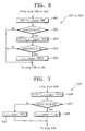
- FIG. 6 illustrates the preliminary compensation routine (step 507 or 520) of the program of FIG. 5.
- a difference "CRC” between the estimated charge capacity “rc_capaa” and the rated charge capacity “TRC” of the secondary battery 11 (see FIG. 1) is calculated (step 601).
- the absolute difference "abs(CRC)” is compared to an upper limit value of 50 (step 620). If the absolute difference "abs(CRC)" is more than 50, the process returns to the step 508 or 521 of FIG. 5.
- FIG. 7 illustrates the final compensation routines (step 539) of FIG. 5.
- the difference "CFCC” between the reference full charge capacity "f_c_capac” for the previous period of rime and the rated full charge capacity "TFCC” is calculated (step 606).
- the absolute difference "CFCC” is compared to a predetermined value of 50 (step 607). If the absolute difference "CFCC” is less than or equal to 50, the reference full charge capacity "f_c_capac” for the present period of time is updated with the required full charge capacity "s_dcr” for the present period of time, and then the process moves to the step 540 of FIG. 5 (step 608). Meanwhile, if the absolute difference "CFCC” is more than 50, the reference full charge capacity "f_c_capac” for the present period of time is updated with the rated full charge capacity "TFCC” (step 609).
- the reference full charge capacity "f_c_capac” is updated with required full charge capacity "s_dcr" which is obtained during the discharge mode.
- the reference full charge capacity "f_c_capac” is updated based on the discharging characteristics which vary with time, so that the charge and discharge statuses of the secondary battery can be monitored and controlled with accurate data.
- the charge status of the secondary battery is determined using the average voltage value of the secondary cell, and thus more accurate data can be generated.
Landscapes
- Engineering & Computer Science (AREA)
- Manufacturing & Machinery (AREA)
- Chemical & Material Sciences (AREA)
- Chemical Kinetics & Catalysis (AREA)
- Electrochemistry (AREA)
- General Chemical & Material Sciences (AREA)
- Power Engineering (AREA)
- Microelectronics & Electronic Packaging (AREA)
- Charge And Discharge Circuits For Batteries Or The Like (AREA)
- Secondary Cells (AREA)
- Tests Of Electric Status Of Batteries (AREA)
Applications Claiming Priority (2)
| Application Number | Priority Date | Filing Date | Title |
|---|---|---|---|
| KR9914266 | 1999-04-21 | ||
| KR1019990014266A KR100354243B1 (ko) | 1999-04-21 | 1999-04-21 | 이차전지의 충전 및 방전 상태를 모니터링 및 제어하기 위한 데이터를 발생시키는 방법 |
Publications (3)
| Publication Number | Publication Date |
|---|---|
| EP1047173A2 true EP1047173A2 (de) | 2000-10-25 |
| EP1047173A3 EP1047173A3 (de) | 2001-04-11 |
| EP1047173B1 EP1047173B1 (de) | 2006-11-22 |
Family
ID=19581424
Family Applications (1)
| Application Number | Title | Priority Date | Filing Date |
|---|---|---|---|
| EP00302336A Expired - Lifetime EP1047173B1 (de) | 1999-04-21 | 2000-03-22 | Verfahren zur Erzeugung von Daten zur Überwachung und Regelung des Lade- und Entladezustandes einer Sekundärbatterie |
Country Status (6)
| Country | Link |
|---|---|
| US (1) | US6456948B1 (de) |
| EP (1) | EP1047173B1 (de) |
| JP (1) | JP3892641B2 (de) |
| KR (1) | KR100354243B1 (de) |
| CN (1) | CN1175513C (de) |
| DE (1) | DE60031909T2 (de) |
Cited By (1)
| Publication number | Priority date | Publication date | Assignee | Title |
|---|---|---|---|---|
| CN117368743A (zh) * | 2023-12-05 | 2024-01-09 | 深圳市易检车服科技有限公司 | 电池健康状态评估方法、装置、计算机设备及存储介质 |
Families Citing this family (27)
| Publication number | Priority date | Publication date | Assignee | Title |
|---|---|---|---|---|
| EP1284508B1 (de) * | 2001-02-20 | 2010-04-07 | Panasonic Corporation | Batteriepack |
| KR100406796B1 (ko) * | 2001-10-17 | 2003-11-21 | 삼성에스디아이 주식회사 | 이차전지의 유효 만방전 용량을 정밀하게 추정하는 방법 |
| US6892147B2 (en) * | 2003-04-18 | 2005-05-10 | Dell Products L.P. | Information handling system including a power management apparatus capable of independently switching between a primary and secondary battery |
| CN100520431C (zh) * | 2003-07-29 | 2009-07-29 | 松下电动车辆能源股份有限公司 | 二次电池的充放电电量推定方法及装置 |
| US7111180B2 (en) * | 2003-08-29 | 2006-09-19 | Dell Products L.P. | Information handling system interrupting current to external module if current exceeds different current limits when handling system receives current from battery and alternating current source |
| US7525279B2 (en) * | 2004-07-16 | 2009-04-28 | General Electric Company | System and method for minimizing the charge time of a battery |
| KR100601557B1 (ko) * | 2004-08-30 | 2006-07-19 | 삼성에스디아이 주식회사 | 배터리팩의 모니터링 장치 및 그 방법 |
| KR100686794B1 (ko) * | 2005-01-25 | 2007-02-23 | 삼성에스디아이 주식회사 | 배터리팩의 모니터링 장치 및 그 방법 |
| KR100660138B1 (ko) * | 2005-07-06 | 2006-12-21 | 한양대학교 산학협력단 | 공기 살균기 |
| JP4513790B2 (ja) * | 2006-08-23 | 2010-07-28 | 日本電気株式会社 | 充電装置および充電制御方法ならびにプログラム |
| CN101335369B (zh) * | 2007-06-29 | 2010-08-25 | 联想(北京)有限公司 | 移动终端电池的充电管理方法及装置 |
| JP2010172186A (ja) * | 2008-12-26 | 2010-08-05 | Panasonic Corp | 電子機器及びバッテリの残りの使用可能時間を算出する方法 |
| US8405356B2 (en) * | 2010-03-05 | 2013-03-26 | Panasonic Corporation | Full charge capacity value correction circuit, battery pack, and charging system |
| JP2012127744A (ja) * | 2010-12-14 | 2012-07-05 | Sony Corp | 電子機器、バッテリパック及びバッテリパックの容量算出方法 |
| EP2765435A4 (de) * | 2011-10-06 | 2015-07-01 | Hitachi Automotive Systems Ltd | Batteriesteuerung |
| CN102540091B (zh) * | 2011-12-02 | 2015-01-28 | 毛广甫 | 电池组的电池状态及数据检验方法 |
| CN103869255B (zh) * | 2014-03-18 | 2016-06-15 | 南京航空航天大学 | 微小型电动无人机续航时间估算方法 |
| CN105425160B (zh) * | 2014-11-24 | 2018-11-27 | 北京航空航天大学 | 一种基于多轴旋翼无人机的航时确定方法及装置 |
| KR102442187B1 (ko) * | 2015-04-10 | 2022-09-07 | 삼성에스디아이 주식회사 | 배터리 보호 회로 |
| US10128546B2 (en) * | 2016-06-07 | 2018-11-13 | Ford Global Technologies, Llc | Battery communication system for battery packs |
| KR102862040B1 (ko) | 2016-11-22 | 2025-09-19 | 삼성전자주식회사 | 배터리 제어 방법 및 장치 |
| US10994617B2 (en) | 2018-11-19 | 2021-05-04 | Ford Global Technologies, Llc | Distributed battery thermal runaway detection |
| CN111781502B (zh) * | 2019-04-04 | 2022-01-21 | 宁德时代新能源科技股份有限公司 | 电动汽车的电池检测方法、装置和检测设备 |
| CN116368658A (zh) | 2021-03-22 | 2023-06-30 | 宁德时代新能源科技股份有限公司 | 一种电池、用电装置、电池的充电方法及装置 |
| TWI801263B (zh) * | 2022-06-15 | 2023-05-01 | 新普科技股份有限公司 | 電容量估計方法、電池模組及其電器產品 |
| CN118465562B (zh) * | 2024-07-12 | 2024-11-19 | 浙江欣旺达电子有限公司 | 一种电池完全充电容量的更新方法、装置及终端设备 |
| CN118571607B (zh) * | 2024-08-05 | 2024-10-22 | 广东电网有限责任公司中山供电局 | 电抗器减振散热装置 |
Family Cites Families (15)
| Publication number | Priority date | Publication date | Assignee | Title |
|---|---|---|---|---|
| JPS61209372A (ja) * | 1985-03-14 | 1986-09-17 | Matsushita Electric Works Ltd | 電池残量認識回路 |
| GB8817364D0 (en) * | 1988-07-21 | 1988-08-24 | Opalport Electronics Ltd | Battery monitoring system |
| EP0448745B1 (de) | 1990-03-26 | 1995-05-24 | Siemens Aktiengesellschaft | Verfahren und Schaltungsanordnung zur Überwachung einer Batterie auf ihren Betriebszustand und ihre Bereitschaft |
| US5563496A (en) * | 1990-12-11 | 1996-10-08 | Span, Inc. | Battery monitoring and charging control unit |
| JP3027644B2 (ja) * | 1991-12-12 | 2000-04-04 | 富士通株式会社 | 電池残量表示方法及び装置 |
| US5545969A (en) * | 1992-12-02 | 1996-08-13 | Matsushita Electric Industrial Co., Ltd. | Battery residual capacity displaying system with discharged electrical quantity computation section |
| US5600229A (en) * | 1994-03-31 | 1997-02-04 | Samsung Heavy Industries Co., Ltd. | System for monitoring energy performance of secondary battery, and method therefor |
| JP2937796B2 (ja) * | 1994-04-27 | 1999-08-23 | 日本碍子株式会社 | 電力貯蔵用二次電池の充放電電流測定方法及び残存電力量測定方法並びに測定装置 |
| JP3121732B2 (ja) | 1994-11-04 | 2001-01-09 | 三菱電機株式会社 | 二次電池のパラメータ測定方法ならびにそれを用いた二次電池の充放電制御方法および寿命予測方法、ならびに、二次電池の充放電制御装置およびそれを用いた電力貯蔵装置 |
| JP3496311B2 (ja) * | 1994-12-14 | 2004-02-09 | 松下電工株式会社 | 充電式電気機器 |
| US5661393A (en) | 1995-04-03 | 1997-08-26 | Rayovac Corporation | Circuit and method for detecting and indicating the state of charge of a cell or battery |
| JP3009022B2 (ja) * | 1995-04-07 | 2000-02-14 | 矢崎総業株式会社 | 電池残存容量測定方法及びその装置 |
| US5895440A (en) | 1996-12-23 | 1999-04-20 | Cruising Equipment Company, Inc. | Battery monitor and cycle status indicator |
| JPH10275036A (ja) * | 1997-03-28 | 1998-10-13 | Toshiba Corp | 電源制御装置およびコンピュータシステム |
| US6157169A (en) * | 1997-04-30 | 2000-12-05 | Samsung Electronics Co., Ltd. | Monitoring technique for accurately determining residual capacity of a battery |
-
1999
- 1999-04-21 KR KR1019990014266A patent/KR100354243B1/ko not_active Expired - Lifetime
-
2000
- 2000-03-02 US US09/517,531 patent/US6456948B1/en not_active Expired - Lifetime
- 2000-03-22 DE DE60031909T patent/DE60031909T2/de not_active Expired - Lifetime
- 2000-03-22 EP EP00302336A patent/EP1047173B1/de not_active Expired - Lifetime
- 2000-03-24 CN CNB001048236A patent/CN1175513C/zh not_active Expired - Lifetime
- 2000-04-18 JP JP2000116912A patent/JP3892641B2/ja not_active Expired - Lifetime
Cited By (2)
| Publication number | Priority date | Publication date | Assignee | Title |
|---|---|---|---|---|
| CN117368743A (zh) * | 2023-12-05 | 2024-01-09 | 深圳市易检车服科技有限公司 | 电池健康状态评估方法、装置、计算机设备及存储介质 |
| CN117368743B (zh) * | 2023-12-05 | 2024-03-19 | 深圳市易检车服科技有限公司 | 电池健康状态评估方法、装置、计算机设备及存储介质 |
Also Published As
| Publication number | Publication date |
|---|---|
| CN1271188A (zh) | 2000-10-25 |
| KR100354243B1 (ko) | 2002-09-28 |
| US6456948B1 (en) | 2002-09-24 |
| JP3892641B2 (ja) | 2007-03-14 |
| JP2000350372A (ja) | 2000-12-15 |
| DE60031909D1 (de) | 2007-01-04 |
| EP1047173A3 (de) | 2001-04-11 |
| EP1047173B1 (de) | 2006-11-22 |
| DE60031909T2 (de) | 2007-07-05 |
| KR20000066878A (ko) | 2000-11-15 |
| CN1175513C (zh) | 2004-11-10 |
Similar Documents
| Publication | Publication Date | Title |
|---|---|---|
| EP1047173B1 (de) | Verfahren zur Erzeugung von Daten zur Überwachung und Regelung des Lade- und Entladezustandes einer Sekundärbatterie | |
| US5600230A (en) | Smart battery providing programmable remaining capacity and run-time alarms based on battery-specific characteristics | |
| US5572110A (en) | Smart battery charger system | |
| US5541489A (en) | Smart battery power availability feature based on battery-specific characteristics | |
| US5565759A (en) | Smart battery providing battery life and recharge time prediction | |
| JP6991591B2 (ja) | バッテリの充電状態の予測方法 | |
| JP4852015B2 (ja) | 電池管理システム、電池パック、及びその充電状態計測方法 | |
| US6097175A (en) | Method for charging and discharging a smart battery of an electronic equipment | |
| US20140028267A1 (en) | Battery charging method and battery pack utilizing the same | |
| JPH06315233A (ja) | 電池の充電制御方法 | |
| JPH1023674A (ja) | 電池残量予測方法、電池ユニット及び電池ユニットを使用する装置 | |
| JP2003307555A (ja) | 残量予測方法、アナログ−デジタル変換回路、充電制御方法、電池パック、半導体装置及び電池パックを内蔵した携帯型機器 | |
| CN104662766A (zh) | 充电状态运算装置以及充电状态运算方法 | |
| CN112534675A (zh) | 快速电池充电 | |
| JP5114884B2 (ja) | 電池パックおよび検出方法 | |
| EP4053961B1 (de) | Intelligente batterievorrichtung und verfahren zu deren betrieb | |
| JP3405525B2 (ja) | 電池パック制御装置 | |
| JP2003194899A (ja) | 二次電池の有効完全放電容量を精密に推定する方法 | |
| JP4178141B2 (ja) | 充電装置及び充電方法 | |
| US20100033131A1 (en) | Portable device and control method thereof | |
| US12199463B2 (en) | System and method for recharging a battery | |
| JPH10210666A (ja) | 充電制御方法 | |
| JP3666697B2 (ja) | 容量積算方法およびバッテリパック | |
| US20250028005A1 (en) | Battery capacity calculation device and battery capacity calculation method | |
| JP2021090318A (ja) | 電池パック、制御方法およびプログラム |
Legal Events
| Date | Code | Title | Description |
|---|---|---|---|
| PUAI | Public reference made under article 153(3) epc to a published international application that has entered the european phase |
Free format text: ORIGINAL CODE: 0009012 |
|
| AK | Designated contracting states |
Kind code of ref document: A2 Designated state(s): DE FR GB |
|
| AX | Request for extension of the european patent |
Free format text: AL;LT;LV;MK;RO;SI |
|
| PUAL | Search report despatched |
Free format text: ORIGINAL CODE: 0009013 |
|
| AK | Designated contracting states |
Kind code of ref document: A3 Designated state(s): AT BE CH CY DE DK ES FI FR GB GR IE IT LI LU MC NL PT SE |
|
| AX | Request for extension of the european patent |
Free format text: AL;LT;LV;MK;RO;SI |
|
| 17P | Request for examination filed |
Effective date: 20011008 |
|
| AKX | Designation fees paid |
Free format text: DE FR GB |
|
| GRAP | Despatch of communication of intention to grant a patent |
Free format text: ORIGINAL CODE: EPIDOSNIGR1 |
|
| RAP1 | Party data changed (applicant data changed or rights of an application transferred) |
Owner name: SAMSUNG SDI CO., LTD. |
|
| GRAS | Grant fee paid |
Free format text: ORIGINAL CODE: EPIDOSNIGR3 |
|
| GRAA | (expected) grant |
Free format text: ORIGINAL CODE: 0009210 |
|
| AK | Designated contracting states |
Kind code of ref document: B1 Designated state(s): DE FR GB |
|
| REG | Reference to a national code |
Ref country code: GB Ref legal event code: FG4D |
|
| REF | Corresponds to: |
Ref document number: 60031909 Country of ref document: DE Date of ref document: 20070104 Kind code of ref document: P |
|
| ET | Fr: translation filed | ||
| PLBE | No opposition filed within time limit |
Free format text: ORIGINAL CODE: 0009261 |
|
| STAA | Information on the status of an ep patent application or granted ep patent |
Free format text: STATUS: NO OPPOSITION FILED WITHIN TIME LIMIT |
|
| 26N | No opposition filed |
Effective date: 20070823 |
|
| REG | Reference to a national code |
Ref country code: FR Ref legal event code: PLFP Year of fee payment: 17 |
|
| REG | Reference to a national code |
Ref country code: FR Ref legal event code: PLFP Year of fee payment: 18 |
|
| REG | Reference to a national code |
Ref country code: FR Ref legal event code: PLFP Year of fee payment: 19 |
|
| PGFP | Annual fee paid to national office [announced via postgrant information from national office to epo] |
Ref country code: DE Payment date: 20190312 Year of fee payment: 20 Ref country code: GB Payment date: 20190320 Year of fee payment: 20 Ref country code: FR Payment date: 20190313 Year of fee payment: 20 |
|
| REG | Reference to a national code |
Ref country code: DE Ref legal event code: R071 Ref document number: 60031909 Country of ref document: DE |
|
| REG | Reference to a national code |
Ref country code: GB Ref legal event code: PE20 Expiry date: 20200321 |
|
| PG25 | Lapsed in a contracting state [announced via postgrant information from national office to epo] |
Ref country code: GB Free format text: LAPSE BECAUSE OF EXPIRATION OF PROTECTION Effective date: 20200321 |