EP1045251A2 - Schaltkreis zur Spannungsfeststellung - Google Patents
Schaltkreis zur Spannungsfeststellung Download PDFInfo
- Publication number
- EP1045251A2 EP1045251A2 EP00107196A EP00107196A EP1045251A2 EP 1045251 A2 EP1045251 A2 EP 1045251A2 EP 00107196 A EP00107196 A EP 00107196A EP 00107196 A EP00107196 A EP 00107196A EP 1045251 A2 EP1045251 A2 EP 1045251A2
- Authority
- EP
- European Patent Office
- Prior art keywords
- circuit
- voltage
- detection
- comparison
- power supply
- Prior art date
- Legal status (The legal status is an assumption and is not a legal conclusion. Google has not performed a legal analysis and makes no representation as to the accuracy of the status listed.)
- Withdrawn
Links
Images


Classifications
-
- E—FIXED CONSTRUCTIONS
- E06—DOORS, WINDOWS, SHUTTERS, OR ROLLER BLINDS IN GENERAL; LADDERS
- E06B—FIXED OR MOVABLE CLOSURES FOR OPENINGS IN BUILDINGS, VEHICLES, FENCES OR LIKE ENCLOSURES IN GENERAL, e.g. DOORS, WINDOWS, BLINDS, GATES
- E06B7/00—Special arrangements or measures in connection with doors or windows
- E06B7/02—Special arrangements or measures in connection with doors or windows for providing ventilation, e.g. through double windows; Arrangement of ventilation roses
- E06B7/08—Louvre doors, windows or grilles
- E06B7/084—Louvre doors, windows or grilles with rotatable lamellae
-
- G—PHYSICS
- G01—MEASURING; TESTING
- G01R—MEASURING ELECTRIC VARIABLES; MEASURING MAGNETIC VARIABLES
- G01R19/00—Arrangements for measuring currents or voltages or for indicating presence or sign thereof
- G01R19/165—Indicating that current or voltage is either above or below a predetermined value or within or outside a predetermined range of values
- G01R19/16566—Circuits and arrangements for comparing voltage or current with one or several thresholds and for indicating the result not covered by subgroups G01R19/16504, G01R19/16528, G01R19/16533
- G01R19/16576—Circuits and arrangements for comparing voltage or current with one or several thresholds and for indicating the result not covered by subgroups G01R19/16504, G01R19/16528, G01R19/16533 comparing DC or AC voltage with one threshold
-
- G—PHYSICS
- G01—MEASURING; TESTING
- G01R—MEASURING ELECTRIC VARIABLES; MEASURING MAGNETIC VARIABLES
- G01R19/00—Arrangements for measuring currents or voltages or for indicating presence or sign thereof
- G01R19/165—Indicating that current or voltage is either above or below a predetermined value or within or outside a predetermined range of values
- G01R19/16533—Indicating that current or voltage is either above or below a predetermined value or within or outside a predetermined range of values characterised by the application
- G01R19/16538—Indicating that current or voltage is either above or below a predetermined value or within or outside a predetermined range of values characterised by the application in AC or DC supplies
Definitions
- the power source voltage detecting circuit 10 includes a detection voltage generating circuit 11 , a reference voltage generating circuit 12 , and a comparison circuit 13 .
- the detection voltage generating circuit 11 generates a detection voltage 11a for monitoring a power supply voltage.
- the reference voltage generating circuit 12 generates a reference voltage 12a which is constant and independent of the power supply voltage.
- the comparison circuit 13 compares the detection voltage 11a with the reference voltage 12a and outputs the result of the comparison as a comparison circuit output signal 13a .
- a power supply voltage dividing circuit may, for example, be used as the detection voltage generating circuit 11 .
- a bandgap reference circuit may, for example, be used as the reference voltage generating circuit 12 .
- a voltage detecting method for detecting a state of a first voltage includes the step of intermittently comparing a detection voltage as a monitor of the first voltage with a reference voltage, and outputting a result of the comparison as a detection signal.
- the voltage detecting circuit detects primarily a voltage (hereinafter referred to as a first voltage).
- the first voltage may be a power supply voltage for the voltage detecting circuit or an integrated circuit carrying the voltage detecting circuit; or an arbitrary power voltage other than the power supply voltage (e.g., a power supply voltage of another integrated circuit or a well bias required for DRAM).
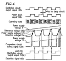
- the comparison circuit 130 in a time period during which the power down signal 150a has a HIGH level, the comparison circuit 130 as well as the detection voltage generating circuit 110 and the reference voltage generating circuit 120 carry out the comparison operation. In a time period during which the power down signal 150a has a LOW level, these circuits are in a power down state so that the comparison operation is not carried out. As described above, the detection voltage generating circuit 110 , the reference voltage generating circuit 120 , and the comparison circuit 130 each have a power down function. By the intermittent comparison operation, the comparison circuit 130 outputs the comparison circuit output signal 130a as shown in Figure 4 .
- the voltage detection circuit 100 has the same comparison operation as that of the conventional example in the time period during which the power down signal 150a has the HIGH level.
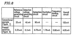
- a voltage detecting circuit for detecting a power supply voltage according to Example 2 of this invention will be described with reference to Figures 6 and 7 .
- the voltage detecting device of Example 2 differs from that of Example 1 in that the voltage detecting device of Example 2 is provided with a frequency dividing circuit for dividing the frequency of a pulse signal output from an oscillation circuit. Except for this point, the voltage detecting device of Example 2 has the same structure as that of Example 1.
Landscapes
- Engineering & Computer Science (AREA)
- Power Engineering (AREA)
- Physics & Mathematics (AREA)
- General Physics & Mathematics (AREA)
- Civil Engineering (AREA)
- Structural Engineering (AREA)
- Measurement Of Current Or Voltage (AREA)
- Manipulation Of Pulses (AREA)
Applications Claiming Priority (2)
| Application Number | Priority Date | Filing Date | Title |
|---|---|---|---|
| JP10625399 | 1999-04-14 | ||
| JP10625399 | 1999-04-14 |
Publications (2)
| Publication Number | Publication Date |
|---|---|
| EP1045251A2 true EP1045251A2 (de) | 2000-10-18 |
| EP1045251A3 EP1045251A3 (de) | 2001-09-12 |
Family
ID=14428951
Family Applications (1)
| Application Number | Title | Priority Date | Filing Date |
|---|---|---|---|
| EP00107196A Withdrawn EP1045251A3 (de) | 1999-04-14 | 2000-04-12 | Schaltkreis zur Spannungsfeststellung |
Country Status (3)
| Country | Link |
|---|---|
| US (1) | US6407571B1 (de) |
| EP (1) | EP1045251A3 (de) |
| KR (1) | KR20010014722A (de) |
Cited By (2)
| Publication number | Priority date | Publication date | Assignee | Title |
|---|---|---|---|---|
| DE10164359A1 (de) * | 2001-11-30 | 2003-06-12 | Hynix Semiconductor Inc | Versorgungsspannungspegeldetektor |
| CN102830271A (zh) * | 2011-06-15 | 2012-12-19 | 联咏科技股份有限公司 | 电压检测方法及电压检测电路 |
Families Citing this family (38)
| Publication number | Priority date | Publication date | Assignee | Title |
|---|---|---|---|---|
| US6658061B1 (en) * | 2001-12-19 | 2003-12-02 | Sun Microsystems, Inc. | Marginable clock-derived reference voltage method and apparatus |
| US6747470B2 (en) * | 2001-12-19 | 2004-06-08 | Intel Corporation | Method and apparatus for on-die voltage fluctuation detection |
| US7315178B1 (en) | 2002-04-16 | 2008-01-01 | Transmeta Corporation | System and method for measuring negative bias thermal instability with a ring oscillator |
| US7180322B1 (en) * | 2002-04-16 | 2007-02-20 | Transmeta Corporation | Closed loop feedback control of integrated circuits |
| US6882172B1 (en) * | 2002-04-16 | 2005-04-19 | Transmeta Corporation | System and method for measuring transistor leakage current with a ring oscillator |
| US6744271B2 (en) * | 2002-04-30 | 2004-06-01 | Infineon Technologies Ag | Internal generation of reference voltage |
| US7886164B1 (en) | 2002-11-14 | 2011-02-08 | Nvidia Corporation | Processor temperature adjustment system and method |
| US7882369B1 (en) | 2002-11-14 | 2011-02-01 | Nvidia Corporation | Processor performance adjustment system and method |
| US7849332B1 (en) | 2002-11-14 | 2010-12-07 | Nvidia Corporation | Processor voltage adjustment system and method |
| US7949864B1 (en) | 2002-12-31 | 2011-05-24 | Vjekoslav Svilan | Balanced adaptive body bias control |
| US7649402B1 (en) | 2003-12-23 | 2010-01-19 | Tien-Min Chen | Feedback-controlled body-bias voltage source |
| US7304503B2 (en) | 2004-06-08 | 2007-12-04 | Transmeta Corporation | Repeater circuit with high performance repeater mode and normal repeater mode, wherein high performance repeater mode has fast reset capability |
| US7656212B1 (en) | 2004-06-08 | 2010-02-02 | Robert Paul Masleid | Configurable delay chain with switching control for tail delay elements |
| US7405597B1 (en) * | 2005-06-30 | 2008-07-29 | Transmeta Corporation | Advanced repeater with duty cycle adjustment |
| US7173455B2 (en) | 2004-06-08 | 2007-02-06 | Transmeta Corporation | Repeater circuit having different operating and reset voltage ranges, and methods thereof |
| US7498846B1 (en) | 2004-06-08 | 2009-03-03 | Transmeta Corporation | Power efficient multiplexer |
| US7142018B2 (en) | 2004-06-08 | 2006-11-28 | Transmeta Corporation | Circuits and methods for detecting and assisting wire transitions |
| US7635992B1 (en) | 2004-06-08 | 2009-12-22 | Robert Paul Masleid | Configurable tapered delay chain with multiple sizes of delay elements |
| US7336103B1 (en) * | 2004-06-08 | 2008-02-26 | Transmeta Corporation | Stacked inverter delay chain |
| US7071747B1 (en) | 2004-06-15 | 2006-07-04 | Transmeta Corporation | Inverting zipper repeater circuit |
| US7330080B1 (en) | 2004-11-04 | 2008-02-12 | Transmeta Corporation | Ring based impedance control of an output driver |
| US7592842B2 (en) * | 2004-12-23 | 2009-09-22 | Robert Paul Masleid | Configurable delay chain with stacked inverter delay elements |
| US7739531B1 (en) | 2005-03-04 | 2010-06-15 | Nvidia Corporation | Dynamic voltage scaling |
| US20070013425A1 (en) * | 2005-06-30 | 2007-01-18 | Burr James B | Lower minimum retention voltage storage elements |
| US7663408B2 (en) * | 2005-06-30 | 2010-02-16 | Robert Paul Masleid | Scannable dynamic circuit latch |
| JP4925630B2 (ja) * | 2005-09-06 | 2012-05-09 | 株式会社アドバンテスト | 試験装置および試験方法 |
| US7394681B1 (en) | 2005-11-14 | 2008-07-01 | Transmeta Corporation | Column select multiplexer circuit for a domino random access memory array |
| US7642866B1 (en) | 2005-12-30 | 2010-01-05 | Robert Masleid | Circuits, systems and methods relating to a dynamic dual domino ring oscillator |
| US7414485B1 (en) | 2005-12-30 | 2008-08-19 | Transmeta Corporation | Circuits, systems and methods relating to dynamic ring oscillators |
| US7710105B2 (en) * | 2006-03-14 | 2010-05-04 | Atmel Corporation | Circuit reset testing methods |
| US7519486B2 (en) * | 2006-03-31 | 2009-04-14 | Atmel Corporation | Method and apparatus to test the power-on-reset trip point of an integrated circuit |
| US7495466B1 (en) | 2006-06-30 | 2009-02-24 | Transmeta Corporation | Triple latch flip flop system and method |
| US7710153B1 (en) | 2006-06-30 | 2010-05-04 | Masleid Robert P | Cross point switch |
| US9134782B2 (en) | 2007-05-07 | 2015-09-15 | Nvidia Corporation | Maintaining optimum voltage supply to match performance of an integrated circuit |
| US8370663B2 (en) | 2008-02-11 | 2013-02-05 | Nvidia Corporation | Power management with dynamic frequency adjustments |
| US9256265B2 (en) | 2009-12-30 | 2016-02-09 | Nvidia Corporation | Method and system for artificially and dynamically limiting the framerate of a graphics processing unit |
| US9830889B2 (en) | 2009-12-31 | 2017-11-28 | Nvidia Corporation | Methods and system for artifically and dynamically limiting the display resolution of an application |
| US8839006B2 (en) | 2010-05-28 | 2014-09-16 | Nvidia Corporation | Power consumption reduction systems and methods |
Citations (9)
| Publication number | Priority date | Publication date | Assignee | Title |
|---|---|---|---|---|
| JPS582674A (ja) * | 1981-06-29 | 1983-01-08 | Mitsubishi Electric Corp | 蓄電池電圧検査装置 |
| EP0207159A1 (de) * | 1984-11-12 | 1987-01-07 | Fanuc Ltd. | Spannungskomparator mit geringem leistungsverbrauch |
| DE4233780A1 (de) * | 1991-10-09 | 1993-04-22 | Matsushita Electric Ind Co Ltd | Empfaenger mit intermittierendem betrieb |
| JPH05133985A (ja) * | 1991-11-15 | 1993-05-28 | Hitachi Ltd | 電源電圧監視回路 |
| US5387820A (en) * | 1991-08-08 | 1995-02-07 | Matsushita Electric Industrial Co., Ltd. | Power supply circuit |
| EP0787993A1 (de) * | 1995-08-21 | 1997-08-06 | Matsushita Electronics Corporation | Spannungsdetektor , strom-ein-/aus-rücksetzschaltung und halbleitergerät |
| JPH116885A (ja) * | 1997-06-16 | 1999-01-12 | Seiko Epson Corp | 発電手段を備えた電子機器 |
| JPH11258279A (ja) * | 1998-03-10 | 1999-09-24 | Omron Corp | 電源電圧検出装置およびこれを用いた制御機器 |
| JPH11266148A (ja) * | 1998-03-17 | 1999-09-28 | Matsushita Electric Ind Co Ltd | 電圧検出回路 |
Family Cites Families (3)
| Publication number | Priority date | Publication date | Assignee | Title |
|---|---|---|---|---|
| US4093909A (en) | 1976-07-21 | 1978-06-06 | General Electric Company | Method and apparatus for operating a semiconductor integrated circuit at minimum power requirements |
| JPH0298672A (ja) | 1988-10-05 | 1990-04-11 | Fujitsu Ltd | 電圧低下検出方法 |
| US6085342A (en) * | 1997-05-06 | 2000-07-04 | Telefonaktiebolaget L M Ericsson (Publ) | Electronic system having a chip integrated power-on reset circuit with glitch sensor |
-
2000
- 2000-04-12 US US09/547,614 patent/US6407571B1/en not_active Expired - Fee Related
- 2000-04-12 EP EP00107196A patent/EP1045251A3/de not_active Withdrawn
- 2000-04-12 KR KR1020000019207A patent/KR20010014722A/ko active Search and Examination
Patent Citations (9)
| Publication number | Priority date | Publication date | Assignee | Title |
|---|---|---|---|---|
| JPS582674A (ja) * | 1981-06-29 | 1983-01-08 | Mitsubishi Electric Corp | 蓄電池電圧検査装置 |
| EP0207159A1 (de) * | 1984-11-12 | 1987-01-07 | Fanuc Ltd. | Spannungskomparator mit geringem leistungsverbrauch |
| US5387820A (en) * | 1991-08-08 | 1995-02-07 | Matsushita Electric Industrial Co., Ltd. | Power supply circuit |
| DE4233780A1 (de) * | 1991-10-09 | 1993-04-22 | Matsushita Electric Ind Co Ltd | Empfaenger mit intermittierendem betrieb |
| JPH05133985A (ja) * | 1991-11-15 | 1993-05-28 | Hitachi Ltd | 電源電圧監視回路 |
| EP0787993A1 (de) * | 1995-08-21 | 1997-08-06 | Matsushita Electronics Corporation | Spannungsdetektor , strom-ein-/aus-rücksetzschaltung und halbleitergerät |
| JPH116885A (ja) * | 1997-06-16 | 1999-01-12 | Seiko Epson Corp | 発電手段を備えた電子機器 |
| JPH11258279A (ja) * | 1998-03-10 | 1999-09-24 | Omron Corp | 電源電圧検出装置およびこれを用いた制御機器 |
| JPH11266148A (ja) * | 1998-03-17 | 1999-09-28 | Matsushita Electric Ind Co Ltd | 電圧検出回路 |
Cited By (4)
| Publication number | Priority date | Publication date | Assignee | Title |
|---|---|---|---|---|
| DE10164359A1 (de) * | 2001-11-30 | 2003-06-12 | Hynix Semiconductor Inc | Versorgungsspannungspegeldetektor |
| US6639419B2 (en) | 2001-11-30 | 2003-10-28 | Hynix Semiconductor | Supply voltage level detector |
| DE10164359B4 (de) * | 2001-11-30 | 2008-10-16 | Hynix Semiconductor Inc., Ichon | Versorgungsspannungspegeldetektor |
| CN102830271A (zh) * | 2011-06-15 | 2012-12-19 | 联咏科技股份有限公司 | 电压检测方法及电压检测电路 |
Also Published As
| Publication number | Publication date |
|---|---|
| US6407571B1 (en) | 2002-06-18 |
| KR20010014722A (ko) | 2001-02-26 |
| EP1045251A3 (de) | 2001-09-12 |
Similar Documents
| Publication | Publication Date | Title |
|---|---|---|
| US6407571B1 (en) | Voltage detecting circuit for a power system | |
| US6510400B1 (en) | Temperature control circuit for central processing unit | |
| US7908508B2 (en) | Low power method of responsively initiating fast response to a detected change of condition | |
| US7489118B2 (en) | Method and apparatus for high-efficiency DC stabilized power supply capable of effectively reducing noises and ripples | |
| US20010017566A1 (en) | Charge pump type voltage conversion circuit having small ripple voltage components | |
| TWI285302B (en) | Logic system with adaptive supply voltage control | |
| KR100668650B1 (ko) | 클럭발생회로 및 클럭발생방법 | |
| US6828848B2 (en) | Integrated circuit device capable of optimizing operating performance according to consumed power | |
| CN111106831A (zh) | 振荡频率控制系统及方法 | |
| US11630161B1 (en) | Flexible circuit for droop detection | |
| EP1148507B1 (de) | Speisespannungsdetektorschaltung | |
| EP1180689A2 (de) | Frequenzbestimmungsschaltkreis für eine Datenverarbeitungseinheit | |
| JP3042473B2 (ja) | クロックバッファ回路 | |
| JP3090031B2 (ja) | Dc/dcコンバータ | |
| JP3987681B2 (ja) | 消費電力低減回路 | |
| JP2000356655A (ja) | 電圧検出回路 | |
| JP2006246367A (ja) | 半導体集積回路及び半導体集積回路のリセット解除方法 | |
| US20230195207A1 (en) | Electronic device and method of controlling temperature in same | |
| KR100398568B1 (ko) | 내부 전원전압 발생기 | |
| US6137279A (en) | Adjustable power control module and applications thereof | |
| KR100575881B1 (ko) | 고전압 발생기용 고전압 검출기 | |
| CN117762230A (zh) | 唤醒电路以及唤醒方法 | |
| JP2000077999A (ja) | 半導体集積回路 | |
| JPH0619586A (ja) | 電圧変動に適応可能な給電回路 | |
| KR20220059982A (ko) | 전압 변환기, 전압 변환기를 포함하는 스토리지 장치, 그리고 전압 변환기의 동작 방법 |
Legal Events
| Date | Code | Title | Description |
|---|---|---|---|
| PUAI | Public reference made under article 153(3) epc to a published international application that has entered the european phase |
Free format text: ORIGINAL CODE: 0009012 |
|
| AK | Designated contracting states |
Kind code of ref document: A2 Designated state(s): AT BE CH CY DE DK ES FI FR GB GR IE IT LI LU MC NL PT SE |
|
| AX | Request for extension of the european patent |
Free format text: AL;LT;LV;MK;RO;SI |
|
| PUAL | Search report despatched |
Free format text: ORIGINAL CODE: 0009013 |
|
| AK | Designated contracting states |
Kind code of ref document: A3 Designated state(s): AT BE CH CY DE DK ES FI FR GB GR IE IT LI LU MC NL PT SE |
|
| AX | Request for extension of the european patent |
Free format text: AL;LT;LV;MK;RO;SI |
|
| STAA | Information on the status of an ep patent application or granted ep patent |
Free format text: STATUS: THE APPLICATION HAS BEEN WITHDRAWN |
|
| 18W | Application withdrawn |
Withdrawal date: 20020225 |
|
| 17P | Request for examination filed |
Effective date: 20020219 |