EP1044847A2 - Scheinwerfer-Leuchten-Einheit für Kraftfahrzeuge - Google Patents
Scheinwerfer-Leuchten-Einheit für Kraftfahrzeuge Download PDFInfo
- Publication number
- EP1044847A2 EP1044847A2 EP00107291A EP00107291A EP1044847A2 EP 1044847 A2 EP1044847 A2 EP 1044847A2 EP 00107291 A EP00107291 A EP 00107291A EP 00107291 A EP00107291 A EP 00107291A EP 1044847 A2 EP1044847 A2 EP 1044847A2
- Authority
- EP
- European Patent Office
- Prior art keywords
- headlight
- lamp
- tension spring
- side wall
- lamp unit
- Prior art date
- Legal status (The legal status is an assumption and is not a legal conclusion. Google has not performed a legal analysis and makes no representation as to the accuracy of the status listed.)
- Withdrawn
Links
- 238000000034 method Methods 0.000 description 3
- 230000001154 acute effect Effects 0.000 description 2
- 230000015572 biosynthetic process Effects 0.000 description 1
- 230000002093 peripheral effect Effects 0.000 description 1
Images


Classifications
-
- B—PERFORMING OPERATIONS; TRANSPORTING
- B60—VEHICLES IN GENERAL
- B60Q—ARRANGEMENT OF SIGNALLING OR LIGHTING DEVICES, THE MOUNTING OR SUPPORTING THEREOF OR CIRCUITS THEREFOR, FOR VEHICLES IN GENERAL
- B60Q1/00—Arrangement of optical signalling or lighting devices, the mounting or supporting thereof or circuits therefor
- B60Q1/0029—Spatial arrangement
- B60Q1/0041—Spatial arrangement of several lamps in relation to each other
- B60Q1/0047—Signalling unit mounted on a headlamp unit
-
- B—PERFORMING OPERATIONS; TRANSPORTING
- B60—VEHICLES IN GENERAL
- B60Q—ARRANGEMENT OF SIGNALLING OR LIGHTING DEVICES, THE MOUNTING OR SUPPORTING THEREOF OR CIRCUITS THEREFOR, FOR VEHICLES IN GENERAL
- B60Q1/00—Arrangement of optical signalling or lighting devices, the mounting or supporting thereof or circuits therefor
- B60Q1/26—Arrangement of optical signalling or lighting devices, the mounting or supporting thereof or circuits therefor the devices being primarily intended to indicate the vehicle, or parts thereof, or to give signals, to other traffic
- B60Q1/28—Arrangement of optical signalling or lighting devices, the mounting or supporting thereof or circuits therefor the devices being primarily intended to indicate the vehicle, or parts thereof, or to give signals, to other traffic for indicating front of vehicle
Definitions
- the invention relates to a headlight-lamp unit for motor vehicles, which in a body opening can be inserted and fastened to the body, with a Luminaire and a headlight, which means on a side wall of the luminaire attacking on the one hand and on the other side of the headlight Tension spring are releasably connected to each other, and that means are provided for Bring the tension spring in a the specified relative position of the lamp Headlight fixing clamping position.
- DE 197 17 785 C1 is a headlight-lamp unit for Motor vehicles known, one between a side wall of the headlamp and a side wall of the lamp arranged tension spring in a the lamp the headlight locking clamping position can be brought.
- Disadvantage of the known locking device is that for moving the tension spring into the clamping position an eccentric device protruding in the horizontal direction as an additional Fastening means is required, which is voluminous and a considerable space required in the lateral direction. It is also disadvantageous in the known headlight-lamp unit that to operate the Eccentric device additionally requires an operating tool.
- the object of the present invention is therefore a Headlight-lamp unit for motor vehicles such that the Attachment of the lamp to the headlights simplified and that the Space requirements for the fasteners is reduced.
- the invention is in connection with the preamble of Claim 1 characterized in that the tension spring by means of a not arranged parallel to the longitudinal axis and linearly movable elongated clamping element can be brought into the clamping position, the Clamping element in an edge area of the headlight and / or the lamp arranged outer actuating end has one hand and one in the direction an inner end of the tapered portion on the other hand has, wherein the clamping element in a central area between the Side walls of the headlamp and the lamp extends.
- the advantage of the headlight-lamp unit according to the invention is that that to bring the tension spring into a lamp with the headlight fixing an elongated clamping element is provided, the is mounted in a linearly movable manner and by moving a tapering section Tension spring can spend in the intended clamping position.
- the linear movement of the clamping element simplifies handling.
- the required force can be due to the shape of the tapered section be given.
- the clamping element with an outer end in An edge region of the headlamp is arranged, the clamping element can be operated manually.
- the elongated design of the Clamping element a space-saving arrangement of the same between one Side wall of the lamp and a side wall of the headlight. It extends the tensioning element is essentially parallel to the side walls Level so that the contour of the facing side walls of the headlamp on the one hand and the luminaire on the other hand evenly formed over the entire surface can be.
- the means for guiding the Tension spring on the one hand and the tensioning element on the other hand in one piece Guide element provided, which is firmly locked on a side wall of the Headlight or the lamp is arranged.
- the guide element is formed in brackets and has two perpendicular to each other Management levels.
- One management level serves to guide the tension spring, in particular a U-shaped tension bracket of the tension spring.
- the other Management level is used to guide the clamping element, with the inside pointing end or the tapered section of the clamping element when locked which intersects a management level, and immersed in the through the Clamp formed opening.
- the guide element requires little Requires space in the horizontal direction and combines several management or Support functions.
- the guide element has one of the Body opening facing away from at least one bracket section, the forms a receiving slot for receiving the tension bracket of the tension spring. He allows the tension spring to be supported during the tensioning process of the same, so that the tension spring be held in the rectilinear position substantially can or does not kink.
- the tapered section of the Clamping element as on a side facing away from the body opening Clamping element arranged bevel, which is an acute angle forms a vertical.
- the inclined surface on the Clamping bracket of the tension spring moves the same continuously into the clamping position.
- the headlight-lamp unit essentially consists of a headlight 1 and a lamp 2 arranged laterally next to the headlight 1, the Headlight 1 and the lamp 2 each on a facing each other Side wall 3 and 4 have fastening means for locking the lamp 2 the headlight 1.
- the side wall 3 of the headlamp 1 is part of one Housing with which the headlight 1 in a body opening Motor vehicle is used.
- the housing does not accommodate one shown reflector and for a light source, not shown.
- the front one The edge of the housing or the side wall 3 has a U-shaped cross section Recording bed 5, in which a web 6 of the housing opening of the headlamp 1 covering lens 7 is cohesively mounted.
- Forming a gap 8 is flush with the lens 7 of the Headlight 1 on a lens 9 of the lamp 2, which is curved in extends a corner region of the motor vehicle.
- the lens 9 is cohesive supported on a peripheral edge 10 of a housing 11. In a central Area, the housing 11 has an opening in which a light source 12 is arranged. In the assembled state, the headlight 1 and the lamp 2 are located at an edge 13 of the body opening.
- fasteners 14 To fasten the lamp 2 to the headlamp 1 are fasteners 14 in an area of the side wall 3 of the headlamp 1 and the side wall 4 of the Light 2 arranged.
- tension spring 16 On the side wall 4 of the lamp 2 is in the area of a central plane 15 horizontally extending tension spring 16 is arranged.
- the tension spring 16 is with a free end 17 by locking on a locking element 18 of the lamp 2 with the same connected.
- the tension spring 16 On the opposite side, the tension spring 16 has free end of a U-shaped clamping bracket 19, which is in one of the Side wall 4 extends vertical plane.
- the clamping bracket 19 is arcuate formed and forms an opening into which a fixed to the side wall 3 Clamping element 20 can engage.
- each flexible retaining tabs 21 In an upper and lower front edge area of the side wall 4 are each flexible retaining tabs 21 extending parallel to the side wall 4 arranged. These retaining tabs 21 engage in a corresponding manner on the side wall 3 of the headlight 1 arranged receiving eyes 22 and allow for a guided relative movement of the lamp 2 to the headlight 1 during assembly and on the other hand an end stop in the relative movement of the Light 2 to the headlight 1, with a flush alignment of the lens 9 to the lens 7 is guaranteed.
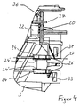
- a guide element 23 is on the side wall 3 of the headlight 1 Locking connected. On a side facing the body opening the guide element 23 each two arranged at a vertical distance from one another and extending in a horizontal plane two locking tabs 24, the a web 25 protruding from the side wall 3 latching. Preferably This web 25 extends to a front edge of the side wall 3 and forms thus a guide for the tension spring 16 during assembly. Inner locking tabs 24 'form a guide surface for the tension spring 16.
- the guide element 23 has on a side facing away from the body opening two protruding to the rear in a horizontal distance from each other Bracket sections 26, each having a horizontally extending receiving slot 27 have.
- the clamping bracket 19 of the tension spring 16 is in the receiving slots 27 stored in the inserted state of the lamp 2, being on an inner edge 28 of the receiving slot 27 of the clamping bracket 19 during the clamping process can support.
- a guide groove 29 or implementation provided so that webs 30 projecting laterally from the tensioning element 20 Play in the guide groove 29 are guided in the vertical direction.
- the guide groove 29 are aligned with each other at the ends of the bracket portion 26.
- the clamping element 20 has one of the Body side facing away from the webs 30 to the rear protruding flag 31, the thickness of which is smaller than the horizontal distance of the Temple sections 26.
- the flag 31 is rigid and points in a lower Section a bevel 32 that is an acute angle to a vertical plane forms.
- the flag 31 is formed tapering downwards or tapering, wherein in the tensioned position of the tension spring 16 an inner end 33 of the Clamping element 20 protrudes below the lower guide groove 29 and a upper end of the slope 32 against the clamping bracket 19 against presses the arcuate part of the inner edge 28 of the receiving slot 27.
- the slope 32 has a trough-shaped at the upper end Recording 34, in which the clamping bracket 19 in the predetermined clamping position snaps into place.
- the tensioning element 20 is essentially rod-shaped, whereby for formation the bevel 32 provided for the actuation of the tensioning element 20, the flag 31 is triangular. This geometric shape enables one Material-saving and stable design of the trained as a slope 32 tapered section of the tensioning element 20.
- the lamp 2 is from the front in horizontal direction in the headlights 1 and the body edge formed opening inserted.
- the retaining tabs 21 engage into the receiving eyes 22 of the side wall 3 of the headlight 1.
- the lamp 2 can thus be continued in a targeted manner in the horizontal direction until the Lens 9 of the lamp 2 flush to form the gap 8 on the Lens 7 of the headlight 1 is arranged. They serve as a stop the side wall 4 of the lamp 2 connected ends 35 of the retaining tabs 21.
- Der Clamping bracket 19 of the tension spring 16 is located in an area of the Receiving slots 27 and is to the rear end of the receiving slot 27 spaced.
- the invention thus advantageously only allows access to the Fasteners from above.
- the actuating end 36 is by a Side wall 3 formed through hole 37 at the top of the same guided.
- the tension spring 16 instead of on the side wall 4 of the lamp 2 on the Attach side wall 3 of the headlight 1.
- the other fasteners are then located on the side wall 4 of the lamp 2. This enables that a fixed to the body lamp 2 with a removable Headlights 1 can be positively connected. Furthermore, there is one such attachment also between two headlight or lamp housings possible. The function of the respective light source is not important.
Landscapes
- Engineering & Computer Science (AREA)
- Mechanical Engineering (AREA)
- Non-Portable Lighting Devices Or Systems Thereof (AREA)
Abstract
Description
- Figur 1
- einen horizontalen mittleren Längsschnitt durch eine Scheinwerfer-Leuchten-Einheit,
- Figur 2
- eine perspektivische Darstellung eines Führungselementes, eines Spannelementes und einer Zugfeder am Anfang des Spannvorgangs der Zugfeder,
- Figur 3
- eine Ansicht einer dem Scheinwerfer zugekehrten Seitenwand der Leuchte und
- Figur 4
- eine teilweise Ansicht der der Leuchte zugewandten Seitenwand des Scheinwerfers.
Claims (10)
- Scheinwerfer-Leuchten-Einheit für Kraftfahrzeuge, die in eine Karosserieöffnung einsetzbar und an der Karosserie befestigbar ist, mit einer Leuchte und einem Scheinwerfer, die mittels einer an einer Seitenwand der Leuchte einerseits und an einer Seitenwand des Scheinwerfers andererseits angreifenden Zugfeder lösbar miteinander verbunden sind, und daß Mittel vorgesehen sind zum Verbringen der Zugfeder in eine die vorgegebene Relativlage der Leuchte zum Scheinwerfer fixierenden Spannposition, dadurch gekennzeichnet, daß die Zugfeder (16) mittels eines nicht parallel zur Längsachse desselben angeordneten und linear beweglichen langgstreckten Spannelementes (20) in die Spannposition bringbar ist, wobei das Spannelement (20) ein in einem Randbereich des Scheinwerfers (1) und/oder der Leuchte (2) angeordnetes äußeres Betätigungsende (36) aufweist einerseits und einen in Richtung eines inneren Endes (33) des Spannelementes (20) sich verjüngenden Abschnitt (32) andererseits aufweist, wobei sich das Spannelement (20) in einem zentralen Bereich zwischen den Seitenwänden (3, 4) des Scheinwerfers (1) und der Leuchte (2) erstreckt.
- Scheinwerfer-Leuchten-Einheit nach Anspruch 1, dadurch gekennzeichnet, daß Mittel zur Führung derart angeordnet sind, daß zum einen die Zugfeder (16) in Montagerichtung der Leuchte (2) oder des Scheinwerfers (1) und zum anderen das Spannelement (20) im wesentlichen senkrecht zur Montagerichtung der Leuchte (2) bzw. des Scheinwerfers (1) geführt sind.
- Scheinwerfer-Leuchten-Einheit nach Anspruch 1 oder 2, dadurch gekennzeichnet, daß als Mittel zur Führung ein Klammerförmiges Führungselement (23) vorgesehen ist, das mit zwei Rastlappen (24, 24') rastend an der Seitenwand (3) des Scheinwerfers (1) befestigt ist, wobei innere Rastlappen (24') jeweils eine Führungsfläche für die Zugfeder (16) bilden.
- Scheinwerfer-Leuchten-Einheit nach einem der Ansprüche 1 bis 3, dadurch gekennzeichnet, daß das Führungselement (23) mindestens eine Führungsnut (29) aufweist, derart, daß das Spannelement (20) in vertikaler Richtung geführt ist.
- Scheinwerfer-Leuchten-Einheit nach einem der Ansprüche 1 bis 4, dadurch gekennzeichnet, daß der verjüngende Abschnitt als eine auf einer der Karosserieöffnung abgewandten Seite des Spannelementes (20) angeordnete Schräge (32) ausgebildet ist, die in eine durch einen Spannbügel (19) am freien Ende (19) der Zugfeder (16) gebildeten Öffnung eingreift zum Verbringen der Zugfeder (16) in die Spannposition.
- Scheinwerfer-Leuchten-Einheit nach einem der Ansprüche 1 bis 5, dadurch gekennzeichnet, daß in einem vorderen Randbereich der Seitenwand (3) des Scheinwerfers (1) zwei parallel zur Montagerichtung orientierte und von der Seitenwand (3) des Scheinwerfers (1) abragende Aufnahmeaugen (22) angeordnet sind, in die jeweils ein einstückig mit der Seitenwand (4) der Leuchte (2) verbundener Haltelappen (21) eingreifbar ist.
- Scheinwerfer-Leuchten-Einheit nach einem der Ansprüche 1 bis 6, dadurch gekennzeichnet, daß die Aufnahmeaugen (22) und die Haltelappen (21) jeweils im vertikalen Abstand zu einander angeordnet sind und daß in einem dazwischenliegenden mittleren Bereich das Führungselement (23) angeordnet ist.
- Scheinwerfer-Leuchten-Einheit nach einem der Ansprüche 1 bis 7, dadurch gekennzeichnet, daß der Haltelappen (21) federnd ausgebildet ist.
- Scheinwerfer-Leuchten-Einheit nach einem der Ansprüche 1 bis 8, dadurch gekennzeichnet, daß das Führungselement (23) auf einer der Karosserieöffnung abgewandten Seite mindestens einen Bügelabschnitt (26) aufweist mit einem Aufnahmeschlitz (27) zur Aufnahme des Spannbügels (19) der Zugfeder (16).
- Scheinwerfer-Leuchten-Einheit nach einem der Ansprüche 1 bis 9, dadurch gekennzeichnet, daß sich der Spannbügel (19) in einer zur Seitenwand (3, 4) der Leuchte (2) und/oder des Scheinerfers (1) senkrechten Ebene erstreckt.
Applications Claiming Priority (2)
| Application Number | Priority Date | Filing Date | Title |
|---|---|---|---|
| DE19916683 | 1999-04-14 | ||
| DE1999116683 DE19916683A1 (de) | 1999-04-14 | 1999-04-14 | Scheinwerfer-Leuchten-Einheit für Kraftfahrzeuge |
Publications (2)
| Publication Number | Publication Date |
|---|---|
| EP1044847A2 true EP1044847A2 (de) | 2000-10-18 |
| EP1044847A3 EP1044847A3 (de) | 2003-01-15 |
Family
ID=7904425
Family Applications (1)
| Application Number | Title | Priority Date | Filing Date |
|---|---|---|---|
| EP00107291A Withdrawn EP1044847A3 (de) | 1999-04-14 | 2000-04-04 | Scheinwerfer-Leuchten-Einheit für Kraftfahrzeuge |
Country Status (3)
| Country | Link |
|---|---|
| EP (1) | EP1044847A3 (de) |
| DE (1) | DE19916683A1 (de) |
| SK (1) | SK5282000A3 (de) |
Citations (1)
| Publication number | Priority date | Publication date | Assignee | Title |
|---|---|---|---|---|
| DE19717785C1 (de) | 1997-04-26 | 1998-10-01 | Volkswagen Ag | Blinkleuchtenbefestigung an einem Kraftfahrzeug |
Family Cites Families (3)
| Publication number | Priority date | Publication date | Assignee | Title |
|---|---|---|---|---|
| IT1245437B (it) * | 1991-03-05 | 1994-09-20 | Carello Spa | Gruppo ottico per veicoli |
| DE4406393A1 (de) * | 1994-02-26 | 1995-08-31 | Bosch Gmbh Robert | Scheinwerfer-Leuchteneinheit für Fahrzeuge |
| DE19742816A1 (de) * | 1997-09-27 | 1999-04-01 | Volkswagen Ag | Befestigungssystem für eine Blinkleuchte |
-
1999
- 1999-04-14 DE DE1999116683 patent/DE19916683A1/de not_active Withdrawn
-
2000
- 2000-04-04 EP EP00107291A patent/EP1044847A3/de not_active Withdrawn
- 2000-04-11 SK SK5282000A patent/SK5282000A3/sk unknown
Patent Citations (1)
| Publication number | Priority date | Publication date | Assignee | Title |
|---|---|---|---|---|
| DE19717785C1 (de) | 1997-04-26 | 1998-10-01 | Volkswagen Ag | Blinkleuchtenbefestigung an einem Kraftfahrzeug |
Also Published As
| Publication number | Publication date |
|---|---|
| SK5282000A3 (en) | 2000-11-07 |
| DE19916683A1 (de) | 2000-10-19 |
| EP1044847A3 (de) | 2003-01-15 |
Similar Documents
| Publication | Publication Date | Title |
|---|---|---|
| EP2298600B1 (de) | Frontendmodul für Fahrzeuge | |
| DE4332286C2 (de) | Stoßfänger-Befestigungsvorrichtung | |
| AT519077B1 (de) | Vorrichtung zur lösbaren Befestigung einer Frontblende an einem Schubkasten und Verfahren zur Montage oder Demontage einer Frontblende an einem Schubkasten | |
| EP2762390A1 (de) | Befestigungsvorrichtung sowie Ausrichtverfahren für Anbauteile von Fahrzeugen | |
| DE3902399A1 (de) | Zierleistenhalter | |
| DE10032094A1 (de) | Kasten | |
| EP1912827B1 (de) | Vorrichtung zur justierbaren befestigung eines scheinwerfers | |
| DE3711432C2 (de) | ||
| DE10029102B4 (de) | Vorrichtung zum Befestigen einer Leuchte | |
| DE19811165B4 (de) | Positionierelement zur Ausrichtung von Karosserieteilen | |
| DE19730269C2 (de) | Vorrichtung zum Befestigen eines ersten Teils mit einem zweiten Teil | |
| DE9214388U1 (de) | Kunststoff-Halteclip für Schutz-, Zierleisten o.dgl., insbesondere an Kraftfahrzeugen | |
| DE2844838A1 (de) | Schraubzwinge | |
| DE4124528C1 (en) | Solid car roof with sun roof aperture - has threaded adjuster with two parts, effective in opposite directions via link | |
| DE102009058815B4 (de) | Haltevorrichtung für Anbauteile von Fahrzeugen | |
| DE102004038433A1 (de) | Verdeckkastendeckel für Kraftfahrzeuge | |
| DE19511066C1 (de) | Schiebehimmel für Kraftfahrzeugdächer | |
| DE4230082A1 (de) | Rahmenkonstruktion eines sonnendachs | |
| DE19916683A1 (de) | Scheinwerfer-Leuchten-Einheit für Kraftfahrzeuge | |
| DE29602125U1 (de) | Signalleuchte für Fahrzeuge | |
| DE10026315B4 (de) | Scheinwerfer-Reinigungsvorrichtung | |
| DE29923248U1 (de) | Scheinwerfer-Leuchten-Einheit für Kraftfahrzeuge | |
| DE10104757B4 (de) | Befestigungsvorrichtung zur verstellbaren Befestigung eines Fahrzeugteils | |
| DE102023125315B4 (de) | Fahrzeugdach mit Lagereinheiten für Wickelwelle | |
| DE3625785A1 (de) | Auto-dachtraeger fuer ein autodach ohne regenrinne |
Legal Events
| Date | Code | Title | Description |
|---|---|---|---|
| PUAI | Public reference made under article 153(3) epc to a published international application that has entered the european phase |
Free format text: ORIGINAL CODE: 0009012 |
|
| AK | Designated contracting states |
Kind code of ref document: A2 Designated state(s): AT BE CH CY DE DK ES FI FR GB GR IE IT LI LU MC NL PT SE |
|
| AX | Request for extension of the european patent |
Free format text: AL;LT;LV;MK;RO;SI |
|
| PUAL | Search report despatched |
Free format text: ORIGINAL CODE: 0009013 |
|
| AK | Designated contracting states |
Kind code of ref document: A3 Designated state(s): AT BE CH CY DE DK ES FI FR GB GR IE IT LI LU MC NL PT SE |
|
| AX | Request for extension of the european patent |
Free format text: AL;LT;LV;MK;RO;SI |
|
| RIC1 | Information provided on ipc code assigned before grant |
Free format text: 7B 60Q 1/00 A, 7B 60Q 1/28 B |
|
| AKX | Designation fees paid | ||
| REG | Reference to a national code |
Ref country code: DE Ref legal event code: 8566 |
|
| STAA | Information on the status of an ep patent application or granted ep patent |
Free format text: STATUS: THE APPLICATION IS DEEMED TO BE WITHDRAWN |
|
| 18D | Application deemed to be withdrawn |
Effective date: 20030716 |