EP1043821A2 - Schaltschrank mit Rahmenschenkeln und Scharnier - Google Patents
Schaltschrank mit Rahmenschenkeln und Scharnier Download PDFInfo
- Publication number
- EP1043821A2 EP1043821A2 EP00810160A EP00810160A EP1043821A2 EP 1043821 A2 EP1043821 A2 EP 1043821A2 EP 00810160 A EP00810160 A EP 00810160A EP 00810160 A EP00810160 A EP 00810160A EP 1043821 A2 EP1043821 A2 EP 1043821A2
- Authority
- EP
- European Patent Office
- Prior art keywords
- control cabinet
- sectional profile
- frame
- shaped cross
- frame legs
- Prior art date
- Legal status (The legal status is an assumption and is not a legal conclusion. Google has not performed a legal analysis and makes no representation as to the accuracy of the status listed.)
- Granted
Links
Images



Classifications
-
- H—ELECTRICITY
- H02—GENERATION; CONVERSION OR DISTRIBUTION OF ELECTRIC POWER
- H02B—BOARDS, SUBSTATIONS OR SWITCHING ARRANGEMENTS FOR THE SUPPLY OR DISTRIBUTION OF ELECTRIC POWER
- H02B1/00—Frameworks, boards, panels, desks, casings; Details of substations or switching arrangements
- H02B1/26—Casings; Parts thereof or accessories therefor
- H02B1/30—Cabinet-type casings; Parts thereof or accessories therefor
- H02B1/32—Mounting of devices therein
-
- H—ELECTRICITY
- H02—GENERATION; CONVERSION OR DISTRIBUTION OF ELECTRIC POWER
- H02B—BOARDS, SUBSTATIONS OR SWITCHING ARRANGEMENTS FOR THE SUPPLY OR DISTRIBUTION OF ELECTRIC POWER
- H02B1/00—Frameworks, boards, panels, desks, casings; Details of substations or switching arrangements
- H02B1/01—Frameworks
- H02B1/013—Profiles for cabinet frames
-
- H—ELECTRICITY
- H02—GENERATION; CONVERSION OR DISTRIBUTION OF ELECTRIC POWER
- H02B—BOARDS, SUBSTATIONS OR SWITCHING ARRANGEMENTS FOR THE SUPPLY OR DISTRIBUTION OF ELECTRIC POWER
- H02B1/00—Frameworks, boards, panels, desks, casings; Details of substations or switching arrangements
- H02B1/01—Frameworks
- H02B1/014—Corner connections for frameworks
Definitions
- the present invention relates to the field of control cabinets. she relates to a control cabinet for receiving electrical and / or electronic Functional units, which control cabinet one from individual similar vertical and horizontal frame legs composed, a cuboid Interior enclosing frame includes, in which Interior space between those belonging to a long side or a transverse side vertical frame legs rails, especially DIN rails, for fastening attachable by electrical and / or electronic functional units are.
- Such a control cabinet is e.g. from the publications DE-C1-33 44 598 or DE-A1-43 40 934 known.
- the invention further relates to a frame leg and a hinge for such a cabinet.
- control cabinets in which in a standardized way and Way electrical and / or electronic functional units such as Circuit breaker, Relays, safety circuit breakers, controls or the like and are to be wired together in such a way that a rectangular frame made of prefabricated individual frame legs more suitable Length is built up.
- the frame legs are at the corner points of the frame either directly connected to each other (see e.g. DE-C1-33 44 598) or assembled using specially designed corner pieces (see e.g. DE-C1-44 39 607 or DE-A1-44 39 624).
- In the frame can then mount mounting rails inside between the vertical frame legs, in particular standardized DIN rails to be screwed on to which the functional units are then attached, e.g. to be snapped up can.
- the control cabinet is completed by the fact that the open sides of the Frame with side walls and possibly a pivotally attached Door are covered, which are attached to the frame.
- the mounting options within the frame can vary be trained. So it is known (DE-A1-43 36 204) the frame legs without training your own fasteners and separate for fastening To provide module rails that are arranged in a grid (alternately round and rectangular) mounting holes are provided and with the Frame legs are connected. But it is also from the two at the beginning mentioned publications (DE-A1-43 40 934 and DE-C1-33 44 598) are known, the To equip the frame legs themselves with assembly holes arranged in a grid. The first solution is comparative in terms of manufacturing and warehousing complex, because different types for the complete frame Hollow profiles are required.
- the object is achieved by the entirety of the features of claim 1.
- the essence of the invention is a cross-sectional profile for the frame legs to choose which is so adapted to the mounting rails to be installed is that there is a flush connection between the respective frame leg and the attached mounting rail results.
- a Cross-sectional profile possible with which a flush connection for at least can reach two different depth mounting rails. Because as mounting rails Usually DIN rails with standardized depths can be used the cross-sectional profile for most applications is defined uniformly.
- a first preferred embodiment of the invention is characterized in that that the frame legs are mirror-symmetrical to a central plane, T-shaped Have cross-sectional profile that the width of the T-shaped cross-sectional profile 3 times the width of the foot of the T-shaped cross-sectional profile is that the width of the foot corresponds to the depth of a first DIN rail, and that the height of the foot of the T-shaped cross-sectional profile of the Depth corresponds to a second DIN rail.
- the T-shaped cross-sectional profile for to a very stable and torsion-resistant frame. Because of the special The choice of dimensions can be different depending on the orientation Fasten deep DIN rails with a flush connection to the frame legs.
- the width of the foot of the T-shaped cross-sectional profile is preferred 15 mm (for DIN rails with 15 mm depth) and the height of the foot 20 mm (for DIN rails with a depth of 20 mm).
- a second preferred embodiment is characterized in that the Frame legs as formed from sheet metal by bending and by welding closed hollow profiles are formed, and that the frame legs a plurality of in the longitudinal direction in a pitch (from e.g. 25 mm or 12.5 mm) arranged mounting openings.
- the closed Hollow profile with high weight has a high mechanical Stability.
- a galvanized steel sheet is preferably used as the sheet.
- a corner piece is provided, on which the corner point striking frame legs are attached with their ends.
- the corner piece has three in orthogonal Legs projecting in spatial directions with a T-shaped cross-sectional profile on which the frame legs can be attached with their ends are. This makes it easy and safe to assemble the frame to reach.
- the frame legs are fastened in the longitudinal direction of the legs equipped with mounting holes arranged in a grid are so that the frame legs with the help of these mounting holes attached to the corner piece after attaching (e.g. screwed or riveted) become.
- control cabinet has a door which hinged to one of the frame legs is that the hinges each have one attached to the frame leg cabinet-side hinge bracket and a door-side attached to the door Hinge brackets include that both hinge brackets each have at least one Roller with a corresponding axle hole for inserting a hinge pin have, and that means are provided on the rollers by means of which Door with its hinge brackets without using the associated hinge pins in the hinge bracket on the cabinet side is centered and temporarily fixed can be. This will assemble the one equipped with a door Control cabinet further facilitated.
- the frame leg according to the invention is characterized in that it is a has a T-shaped cross-sectional profile that is mirror-symmetrical to a central plane, that the width of the T-shaped cross-sectional profile is 3 times the width of the foot of the T-shaped cross-sectional profile is that the width of the foot corresponds to the depth of a first DIN rail, and that the height of the foot of the T-shaped cross-sectional profile corresponds to the depth of a second DIN rail.
- An embodiment of the frame leg is preferred, in which the Frame legs as formed from sheet metal by bending and by welding closed hollow profile is formed, and that the frame leg a plurality of arranged in a longitudinal dimension in the longitudinal direction of the legs Has mounting openings, being in both side surfaces of the foot of the T-shaped cross-sectional profile alternately rectangular as mounting openings Cut-outs for receiving cage nuts and round holes for screwing in of tapping screws are arranged, and being on the bottom and in the side surfaces of the crossbar of the T-shaped cross-sectional profile as mounting openings round holes are arranged.
- the hinge according to the invention is characterized in that the hinge each a cabinet-side hinge bracket and a door-side hinge bracket comprises that both hinge brackets each have at least one roller with one have the corresponding axle hole for inserting a hinge pin, and that are provided on the rollers by means of which the door with its hinge bracket without using the associated hinge pins in the cabinet side
- the hinge bracket can be hung in the center and temporarily fixed.
- a preferred embodiment of the hinge according to the invention draws is characterized by the fact that the centering or fixing means correspond conical centering surfaces on the mutually associated ends of the rollers of the Include hinge bracket.
- the control cabinet according to the invention is essentially based on a (rectangular) Frame made of frame legs with a given cross-sectional profile.
- a preferred embodiment of such a frame is shown in Fig. 1 shown in a top view from above.
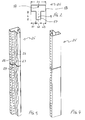
- the frame 55 of the control cabinet 10 is composed of four vertical frame legs 11, .., 14 (or 25 in FIGS. 2 to 4), each of which has a T-shaped cross-sectional profile according to FIG. 2, which is symmetrical to a central plane M and a foot 57 (des T) and a crossbar 58 (des T).
- the vertical frame legs 11, .., 14 are oriented so that the feet 57 of the T-shaped cross-sectional profile point inwards and the feet 57 of the front frame legs 13, 14 directly opposite those of the rear frame legs 11, 12. Between the vertical frame legs 11, .., 14 are at the bottom and top End each arranged in a rectangle horizontal frame legs, from which only the lower frame legs 15, .., 18 are shown in Fig. 1.
- the horizontal frame legs 15, .., 18 are in cross-sectional profile and others Design identical to the vertical frame legs 11, .., 14th In particular are all frame legs 11, .., 18 and 25 according to FIGS. 3 and 4 with in Arranged longitudinally in a predetermined grid dimension (12.5 or 25 mm) rectangular cutouts 26 for receiving cage nuts, as well round holes 27, .., 29 for screwing tapping screws or the like. An alternating sequence of rectangular cutouts 26 and round Holes 27 is on both longitudinal sides of the foot 57 of the T-shaped Cross-sectional profile provided.
- the frame legs 11, .., 18 are closed Hollow profiles formed. They are preferred by (symmetrical to the central plane) Bending made from a sheet metal blank and longitudinal one Welded seam 54 (Fig. 2) welded. A material is preferably used hot-dip galvanized steel sheet used. But it is also conceivable in the Framework of the invention instead of the bent and welded sheet metal profile for example to use an extruded profile made of aluminum.
- the dimensions of the cross-sectional profile according to FIG. 2 are preferably like this chosen that the width b4 of the crossbar 58 is three times the width b2 of the foot 57 corresponds. Because of the symmetry, it follows that the Crossbar 58 protrudes laterally by a width b1 or b3 over foot 57, which is equal to the width b2 of the foot 57 itself.
- a DIN rail 20 with a depth of 20 mm between the vertical frame legs 11 and 12 attached closes with the interior 56 of the Switch cabinet 10 directed surface flush with the bottom of the foot 57 the frame legs 11, 12 and 16. This eliminates distracting paragraphs between the DIN rails and the frame legs avoided.
- DIN rails 21 with a depth of 15 mm between a rear frame leg 12 and a front frame leg 14 are attached. In this Fall closes the surface of the DIN rail 21 facing the interior 56 flush to the inwardly oriented side surface of the crossbar 58 of the frame legs 12 and 14.
- a circuit breaker (23 in FIG. 1) can be operated from the outside be housed in the control cabinet 10, a DIN rail according to FIG. 1 22 screwed from the inside against the feet of the front frame legs 13, 14.
- the circuit breaker 23 can then on the DIN rail 22 of be snapped on at the front and protrudes with its control panel over the front the control cabinet 10 also.
- the front can at least partially with a cover plate 24 which in the area of the circuit breaker 23 a corresponding Cutout has to be covered.
- the front can be used a pivotally mounted on the frame frame 55 door 19 are covered.
- the Total height (foot 57 plus crossbar 58) of the frame legs 25 and the lengths the frame legs 11, .., 18 are now chosen so that the Cabinet dimensions in a 25 mm grid in all three orthogonal axes x, y and z can be expanded as required.
- the zero point NP of the grid is located thereby - as shown in Fig. 1 - on one (left) side of the cabinet (without side wall) in the front level of door 19 and on the floor or base of the control cabinet 10th
- a corner connection 5 preferably with the aid of a correspondingly designed corner piece 33 manufactured.
- the corner piece 33 is, for example, a one-piece Light metal casting.
- the corner piece 33 has three in orthogonal spatial directions protruding legs 34, 35, 36 with a T-shaped cross-sectional profile, on which the frame legs 30, 31, 32 colliding with one another at the corner Ends are pluggable.
- the profile of the protruding legs 34, .., 36 is in its dimensions matched to the hollow profile of the frame legs 30, .., 32.
- fastening holes in the legs 34, .. 37 provided that with attached frame legs 30, .., 32 with correspond to the holes 27 in the frame legs.
- the attachment can done by screwing, but is preferably effected by riveting.
- the corner piece can also advantageously be a threaded hole 38 for screwing in an eyebolt be arranged, with the help of the control cabinet 10 are raised can.
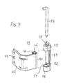
- hinge 41 preferably consists of a cabinet side Hinge bracket 42 and a door-side hinge bracket 47. Both hinge brackets 42 and 47 are made from a sheet metal blank by appropriate bending. For the pivotable connection of the two hinge brackets 42, 47 are on two bracket rollers 44 and 48, 49 formed, each one in the pivot axis Enclose the axle hole 45 or 50.
- the attachment of the Hinge bracket 42, 47 on the frame 55 or on the door 19 is carried out by means of Fastening holes 43 and 52, respectively, for mounting the hinge 41 Hinge bracket 42, 47 brought together so that the axle holes 45 and 50 together swear. Then through the axle holes 50 and 45 from above a hinge pin 53 inserted through a hook-shaped bent upper End is secured against falling down.
- the special feature of the hinge 41 is that on the rollers 44 and 48, 49 means are provided by means of which the door 19 with its hinge brackets 47 without using the associated hinge pin 53 in the cabinet-side hinge bracket 42 can be centered and temporarily fixed.
- This Centering or fixing means comprise corresponding conical centering surfaces 46 and 51 at the mutually associated ends of the rollers 44 and 48, 49 of the hinge bracket 47 or 48, 49.
- the upper roller slides 49 of the door-side hinge bracket 47 with its conical centering surface that the Centering surface 51 is opposite the lower roller 48, but is hidden in FIG. 7, snapping over the conical centering surface 46 of the roller 44 until both surfaces centered on top of each other.
- the roller 49 can slide off the roller 44 then only be achieved by lifting the door 19.
Landscapes
- Engineering & Computer Science (AREA)
- Power Engineering (AREA)
- Patch Boards (AREA)
- Casings For Electric Apparatus (AREA)
- Furniture Connections (AREA)
- Hinges (AREA)
- Motor Or Generator Frames (AREA)
- Switch Cases, Indication, And Locking (AREA)
Abstract
Description
- Fig. 1
- in der Draufsicht von oben ein Rahmengestell aus Rahmenschenkeln mit T-förmigem Querschnittsprofil und beispielhaft montierten DIN-Schienen gemäss einem bevorzugten Ausführungsbeispiel der Erfindung;
- Fig. 2
- das Querschnittsprofil der Rahmenschenkel aus Fig. 1;
- Fig. 3
- in perspektivischer Seitenansicht einen Rahmenschenkel aus Fig. 1;
- Fig. 4
- eine zu Fig. 3 analoge Darstellung, wobei der Rahmenschenkel um seine Längsachse um 180° gedreht ist;
- Fig. 5
- ein Eckstück gemäss einem bevorzugten Ausführungsbeispiel der Erfindung zur Verbindung der in einer Ecke des Rahmengestells zusammenstossenden Rahmenschenkel;
- Fig. 6
- in einem Ausschnitt die bevorzugte schwenkbare Lagerung einer Tür an dem Rahmengestell nach Fig. 1 mittels Scharnieren; und
- Fig. 7
- die Ausbildung eines Scharniers gemäss Fig. 6 in einer Explosionsdarstellung.
- 10
- Schaltschrank
- 11,..,14
- Rahmenschenkel (vertikal)
- 15,..,18
- Rahmenschenkel (horizontal)
- 19
- Tür
- 20,21,22
- DIN-Schiene
- 23
- Leistungsschutzschalter
- 24
- Abdeckplatte
- 25
- Rahmenschenkel (allgemein)
- 26
- Ausschnitt (rechteckig f. Käfigmutter)
- 27,..,29
- Loch (z.B. für Blechschraube)
- 30,31,32
- Rahmenschenkel
- 33
- Eckstück
- 34,35,36
- Schenkel (T-förmig)
- 37
- Befestigungsloch
- 38
- Gewindeloch
- 39
- Absatz
- 40
- Seitenwand
- 41
- Scharnier
- 42
- Scharnierbügel (schrankseitig)
- 43
- Befestigungsloch
- 44
- Rolle
- 45
- Achsloch
- 46
- Zentrierfläche (konisch)
- 47
- Scharnierbügel (türseitig)
- 48,49
- Rolle
- 50
- Achsloch
- 51
- Zentrierfläche (konisch)
- 52
- Befestigungsloch
- 53
- Scharnierbolzen
- 54
- Schweissnaht
- 55
- Rahmengestell
- 56
- Innenraum
- 57
- Fuss (des T-förmigen Querschnittsprofils)
- 58
- Querbalken (des T-förmigen Querschnittsprofils)
- b1,.., b4
- Breite (Querschnittsprofil)
- NP
- Nullpunkt
- M
- Mittelebene
Claims (21)
- Schaltschrank (10) zur Aufnahme von elektrischen und/oder elektronischen Funktionseinheiten, welcher Schaltschrank (10) ein aus einzelnen gleichartigen vertikalen und horizontalen Rahmenschenkeln (11,..,14; 15,..,18; 25; 30,..,33) zusammengesetztes, einen quaderförmigen Innenraum (56) umschliessendes Rahmengestell (55) umfasst, wobei in dem Innenraum (56) zwischen den zu einer Längsseite oder einer Querseite gehörenden vertikalen Rahmenschenkeln (11,..,14) Schienen, insbesondere DIN-Schienen (20, 21, 22), zur Befestigung von elektrischen und/oder elektronischen Funktionseinheiten (23) befestigbar sind, dadurch gekennzeichnet, dass alle Rahmenschenkel (11,..,14; 15,..,18; 25; 30,..,33) ein rechteckiges Querschnittsprofil aufweisen, welches an die Tiefe der Schienen bzw. DIN-Schienen (20, 21, 22) derart angepasst ist, dass bei einer Montage der Schienen (20, 21, 22) an den Rahmenschenkeln (11,..,14) die dem Innenraum (56) des Schaltschrankes (10) zugewandten Seiten der Schienen (20, 21, 22) an die Rahmenschenkel (11,..,14) bündig anschliessen.
- Schaltschrank nach Anspruch 1, dadurch gekennzeichnet, dass die Rahmenschenkel (11,..,14; 15,..,18; 25; 30,..,33) ein zu einer Mittelebene (M) spiegelsymmetrisches, T-förmiges Querschnittsprofil aufweisen.
- Schaltschrank nach Anspruch 2, dadurch gekennzeichnet, dass die Breite (b4) des T-förmigen Querschnittsprofils das 3-fache der Breite (b2) des Fusses (57) des T-förmigen Querschnittsprofils beträgt, und dass die Breite (b2) des Fusses (57) der Tiefe einer ersten DIN-Schiene (21) entspricht.
- Schaltschrank nach Anspruch 2 oder 3, dadurch gekennzeichnet, dass die Höhe (h) des Fusses (57) des T-förmigen Querschnittsprofils der Tiefe einer zweiten DIN-Schiene (20) entspricht.
- Schaltschrank nach Anspruch 4, dadurch gekennzeichnet, dass die Breite (b2) des Fusses (57) des T-förmigen Querschnittsprofils 15 mm und die Höhe (h) des Fusse (57) 20 mm beträgt.
- Schaltschrank nach einem der Ansprüche 2 bis 5, dadurch gekennzeichnet, dass die Rahmenschenkel (11,..,14; 15,..,18; 25; 30,..,33) als aus einem Blech durch Biegen geformte und durch Verschweissen geschlossene Hohlprofile ausgebildet sind.
- Schaltschrank nach Anspruch 6, dadurch gekennzeichnet, dass die Rahmenschenkel (11,..,14; 15,..,18; 25; 30,..,33) eine Vielzahl von in Schenkellängsrichtung in einem Rastermass angeordneten Montageöffnungen (26,..,28) aufweisen.
- Schaltschrank nach Anspruch 7, dadurch gekennzeichnet, dass in beiden Seitenflächen des Fusses (57) des T-förmigen Querschnittsprofils als Montageöffnungen alternierend rechteckige Ausschnitte (26) für die Aufnahme von Käfigmuttern und runde Löcher (27) für das Eindrehen von Blechschrauben angeordnet sind.
- Schaltschrank nach Anspruch 8, dadurch gekennzeichnet, dass auf der Unterseite und in den Seitenflächen des Querbalkens (58) des T-förmigen Querschnittsprofils als Montageöffnungen runde Löcher (28, 29) angeordnet sind.
- Schaltschrank nach einem der Ansprüche 1 bis 9, dadurch gekennzeichnet, dass zum Verbinden der Rahmenschenkel (11,..,14; 15,..,18; 25; 30,..,33) in einem der Eckpunkte des Rahmens (55) jeweils ein Eckstück (33) vorgesehen ist, an welchem die sich im Eckpunkt treffenden Rahmenschenkel (30, 31, 32) mit ihren Enden befestigt werden.
- Schaltschrank nach Anspruch 10, dadurch gekennzeichnet, dass die Rahmenschenkel (11,..,14; 15,..,18; 25; 30,..,33) als Hohlprofile mit T-förmigem Querschnittsprofil ausgebildet sind, und dass das Eckstück drei in orthogonale Raumrichtungen abstehende Schenkel (34, 35, 36) mit einem T-förmigen Querschnittsprofil aufweist, auf welche die Rahmenschenkel (30, 31, 32) mit ihren Enden aufsteckbar sind.
- Schaltschrank nach Anspruch 11, dadurch gekennzeichnet, dass die Rahmenschenkel (11,..,14; 15,..,18; 25; 30,..,33) mit in Schenkellängsrichtung in einem Rastermass angeordneten Montageöffnungen (26,..,29) ausgestattet sind, und dass die Rahmenschenkel (30, 31, 32) unter Zuhilfenahme dieser Montageöffnungen am Eckstück (33) nach dem Aufstecken befestigt werden.
- Schaltschrank nach einem der Ansprüche 10 bis 12, dadurch gekennzeichnet, dass die Eckstücke (33) jeweils ein Gewindeloch (38) zum Einschrauben einer Ringschraube aufweisen.
- Schaltschrank nach einem der Ansprüche 1 bis 13, dadurch gekennzeichnet, dass der Schaltschrank (10) eine Tür (19) aufweist, welche mittels Scharnieren (41) an einem der Rahmenschenkel (11,..,14; 15,..,18; 25; 30,..,33) verschwenkbar befestigt ist.
- Schaltschrank nach Anspruch 14, dadurch gekennzeichnet, dass die Scharniere (41) jeweils einen an dem Rahmenschenkel (11,..,14; 15,..,18; 25; 30,..,33) befestigten schrankseitigen Schamierbügel (42) und einen an der Tür (19) befestigten türseitigen Schamierbügel (47) umfassen, dass beide Schamierbügel (42, 47) jeweils wenigstens eine Rolle (44 bzw. 48, 49) mit einem entsprechenden Achsloch (45 bzw. 50) zum Durchstecken eines Scharnierbolzens (53) aufweisen, und dass an den Rollen (44, 48, 49) Mittel (46, 51) vorgesehen sind, mittels derer die Tür (19) mit ihren Scharnierbügeln (47) ohne Einsatz der zugehörigen Schamierbolzen (53) in die schrankseitigen Schamierbügel (42) zentrierend eingehängt und provisorisch fixiert werden kann.
- Schaltschrank nach Anspruch 15, dadurch gekennzeichnet, dass die Zentrierungs- bzw. Fixierungsmittel korrespondierende konische Zentrierflächen (46, 51) an den einander zugeordneten Enden der Rollen (44, 48, 49) der Scharnierbügel (47, 48, 49) umfassen.
- Rahmenschenkel für einen Schaltschrank nach einem der Ansprüche 1 bis 16, dadurch gekennzeichnet, dass der Rahmenschenkel (11,..,14; 15,..,18; 25; 30,..,33) ein zu einer Mittelebene (M) spiegelsymmetrisches, T-förmiges Querschnittsprofil aufweist, dass die Breite (b4) des T-förmigen Querschnittsprofils das 3-fache der Breite (b2) des Fusses (57) des T-förmigen Querschnittsprofils beträgt, dass die Breite (b2) des Fusses (57) der Tiefe einer ersten DIN-Schiene (21) entspricht, und dass die Höhe (h) des Fusses (57) des T-förmigen Querschnittsprofils der Tiefe einer zweiten DIN-Schiene (20) entspricht.
- Rahmenschenkel nach Anspruch 17, dadurch gekennzeichnet, dass die Breite (b2) des Fusses (57) des T-förmigen Querschnittsprofils 15 mm und die Höhe (h) des Fusse (57) 20 mm beträgt.
- Rahmenschenkel nach einem der Ansprüche 17 und 18, dadurch gekennzeichnet, dass der Rahmenschenkel (11,..,14; 15,..,18; 25; 30,..,33) als aus einem Blech durch Biegen geformte und durch Verschweissen geschlossenes Hohlprofil ausgebildet ist, und dass der Rahmenschenkel (11,..,14; 15,..,18; 25; 30,..,33) eine Vielzahl von in Schenkellängsrichtung in einem Rastermass angeordneten Montageöffnungen (26,..,28) aufweist, wobei in beiden Seitenflächen des Fusses (57) des T-förmigen Querschnittsprofils als Montageöffnungen alternierend rechteckige Ausschnitte (26) für die Aufnahme von Käfigmuttern und runde Löcher (27) für das Eindrehen von Blechschrauben angeordnet sind, und wobei auf der Unterseite und in den Seitenflächen des Querbalkens (58) des T-förmigen Querschnittsprofils als Montageöffnungen runde Löcher (28, 29) angeordnet sind.
- Scharnier für einen Schaltschrank nach einem der Ansprüche 1 bis 16; dadurch gekennzeichnet, dass das Scharnier (41) jeweils einen schrankseitigen Scharnierbügel (42) und einen türseitigen Schamierbügel (47) umfasst, dass beide Scharnierbügel (42, 47) jeweils wenigstens eine Rolle (44 bzw. 48, 49) mit einem entsprechenden Achsloch (45 bzw. 50) zum Durchstecken eines Scharnierbolzens (53) aufweisen, und dass an den Rollen (44, 48, 49) Mittel (46, 51) vorgesehen sind, mittels derer die Tür (19) mit ihren Scharnierbügeln (47) ohne Einsatz der zugehörigen Schamierbolzen (53) in die schrankseitigen Scharnierbügel (42) zentrierend eingehängt und provisorisch fixiert werden kann.
- Scharnier nach Anspruch 20, dadurch gekennzeichnet, dass die Zentrierungs- bzw. Fixierungsmittel korrespondierende konische Zentrierflächen (46, 51) an den einander zugeordneten Enden der Rollen (44, 48, 49) der Schamierbügel (47, 48, 49) umfassen.
Applications Claiming Priority (2)
| Application Number | Priority Date | Filing Date | Title |
|---|---|---|---|
| CH67499 | 1999-04-09 | ||
| CH67499 | 1999-04-09 |
Publications (3)
| Publication Number | Publication Date |
|---|---|
| EP1043821A2 true EP1043821A2 (de) | 2000-10-11 |
| EP1043821A3 EP1043821A3 (de) | 2000-12-06 |
| EP1043821B1 EP1043821B1 (de) | 2004-09-29 |
Family
ID=4192522
Family Applications (1)
| Application Number | Title | Priority Date | Filing Date |
|---|---|---|---|
| EP00810160A Expired - Lifetime EP1043821B1 (de) | 1999-04-09 | 2000-02-25 | Schaltschrank mit Rahmenschenkeln und Scharnier |
Country Status (8)
| Country | Link |
|---|---|
| EP (1) | EP1043821B1 (de) |
| AT (1) | ATE278258T1 (de) |
| CZ (1) | CZ301733B6 (de) |
| DE (1) | DE50007956D1 (de) |
| ES (1) | ES2228440T3 (de) |
| HU (1) | HU224204B1 (de) |
| NO (1) | NO317970B1 (de) |
| PL (1) | PL195621B1 (de) |
Cited By (3)
| Publication number | Priority date | Publication date | Assignee | Title |
|---|---|---|---|---|
| EP2473685A4 (de) * | 2009-09-02 | 2015-12-09 | Glaend System As | Längenprofilvorrichtung |
| CN107939193A (zh) * | 2017-11-27 | 2018-04-20 | 江苏南瑞帕威尔电气有限公司 | 一种开关柜铰链 |
| CN112271562A (zh) * | 2020-10-16 | 2021-01-26 | 哈尔滨宇龙自动化有限公司 | 一种用于实验教学的电气传动柜及其制造方法 |
Family Cites Families (14)
| Publication number | Priority date | Publication date | Assignee | Title |
|---|---|---|---|---|
| CH285914A (de) * | 1950-05-11 | 1952-09-30 | Ag Gutor Verteilanlagen | Traggestell für elektrische Installationen, insbesondere Verteilanlagen. |
| US3857494A (en) * | 1973-07-16 | 1974-12-31 | Rockwell International Corp | Modular rack assembly |
| DK151830C (da) * | 1984-08-31 | 1988-06-06 | Knudsen Nordisk Elect | Montagebeslag til brug ved montering af byggeblokke |
| DE8511217U1 (de) * | 1985-04-16 | 1985-09-05 | ABN Werner Braun GmbH, 7106 Neuenstadt | Verteilerschrank |
| US5127851A (en) * | 1991-07-25 | 1992-07-07 | Reliance Comm/Tec Corporation | Modular patch panel |
| FR2712434B1 (fr) * | 1993-11-10 | 1996-02-16 | Prod Electro Marche Commu Off | Elément d'ossature de baie électrique ou électronique. |
| DE19503289C1 (de) * | 1995-02-02 | 1996-08-01 | Loh Kg Rittal Werk | Schaltschrank mit Rahmengestell und Montageplatte |
| DE19530017C1 (de) * | 1995-08-16 | 1996-11-21 | Loh Kg Rittal Werk | Montagescharnier |
| US5682301A (en) * | 1996-05-14 | 1997-10-28 | Kraft; James L. | Modular network cabling system for enterprise with multiple sites |
| DE29623559U1 (de) * | 1996-11-19 | 1998-10-01 | Rittal-Werk Rudolf Loh GmbH & Co. KG, 35745 Herborn | Rahmengestell mit mehreren Montageebenen |
| DE19647780C2 (de) * | 1996-11-19 | 1999-12-02 | Loh Kg Rittal Werk | Rahmengestell mit einem Boden- und einem Deckrahmen aus einem Profilstrang |
| DE29623551U1 (de) * | 1996-11-19 | 1998-10-01 | Rittal-Werk Rudolf Loh GmbH & Co. KG, 35745 Herborn | Schaltschrank |
| FR2761206B1 (fr) * | 1997-03-21 | 1999-05-14 | Schneider Electric Sa | Chassis metallique a coin d'assemblage hyperstatique, notamment pour une ossature d'armoire electrique |
| DE29808253U1 (de) * | 1998-05-07 | 1998-10-08 | Striebel & John Gmbh & Co Kg, 77880 Sasbach | Vorrichtung zur Befestigung eines elektrischen Zähler- und/oder Verteilerfeldes in einem Schrankgehäuse |
-
2000
- 2000-02-25 EP EP00810160A patent/EP1043821B1/de not_active Expired - Lifetime
- 2000-02-25 ES ES00810160T patent/ES2228440T3/es not_active Expired - Lifetime
- 2000-02-25 AT AT00810160T patent/ATE278258T1/de not_active IP Right Cessation
- 2000-02-25 DE DE50007956T patent/DE50007956D1/de not_active Expired - Lifetime
- 2000-03-14 HU HU0001148A patent/HU224204B1/hu not_active IP Right Cessation
- 2000-03-21 PL PL339123A patent/PL195621B1/pl unknown
- 2000-04-07 CZ CZ20001283A patent/CZ301733B6/cs not_active IP Right Cessation
- 2000-04-07 NO NO20001824A patent/NO317970B1/no not_active IP Right Cessation
Cited By (3)
| Publication number | Priority date | Publication date | Assignee | Title |
|---|---|---|---|---|
| EP2473685A4 (de) * | 2009-09-02 | 2015-12-09 | Glaend System As | Längenprofilvorrichtung |
| CN107939193A (zh) * | 2017-11-27 | 2018-04-20 | 江苏南瑞帕威尔电气有限公司 | 一种开关柜铰链 |
| CN112271562A (zh) * | 2020-10-16 | 2021-01-26 | 哈尔滨宇龙自动化有限公司 | 一种用于实验教学的电气传动柜及其制造方法 |
Also Published As
| Publication number | Publication date |
|---|---|
| CZ301733B6 (cs) | 2010-06-09 |
| NO20001824L (no) | 2000-10-10 |
| HU0001148D0 (en) | 2000-05-28 |
| HUP0001148A2 (hu) | 2001-04-28 |
| PL195621B1 (pl) | 2007-10-31 |
| HU224204B1 (hu) | 2005-06-28 |
| ATE278258T1 (de) | 2004-10-15 |
| NO20001824D0 (no) | 2000-04-07 |
| CZ20001283A3 (cs) | 2001-03-14 |
| EP1043821B1 (de) | 2004-09-29 |
| ES2228440T3 (es) | 2005-04-16 |
| DE50007956D1 (de) | 2004-11-04 |
| HUP0001148A3 (en) | 2002-05-28 |
| EP1043821A3 (de) | 2000-12-06 |
| PL339123A1 (en) | 2000-10-23 |
| NO317970B1 (no) | 2005-01-17 |
Similar Documents
| Publication | Publication Date | Title |
|---|---|---|
| DE4336204C2 (de) | Rahmengestell für einen Schaltschrank | |
| EP0514668B1 (de) | Schrank | |
| EP0389910A1 (de) | Modulares Gehäusesystem für elektronische Baueinheiten | |
| DE19733435A1 (de) | Bürotisch | |
| DE102011013160B4 (de) | Sockel oder Anbaurahmen für einen Schaltschrank oder ein Rack | |
| DE3917985A1 (de) | Schaltschrank | |
| DE1554274A1 (de) | Zusammenlegbares Regal | |
| EP4064937A1 (de) | Möbelbausatz | |
| EP0773615A1 (de) | Schaltschrank für elektrische Anlagen | |
| EP1043821B1 (de) | Schaltschrank mit Rahmenschenkeln und Scharnier | |
| EP0186857B1 (de) | Case-Gehäusesystem | |
| DE19502648C1 (de) | Tragvorrichtung für ein Podest für mehrgeschossig angeordnete Baustellencontainer | |
| DE1591623B1 (de) | Schrank fuer Geraete der Nachrichtentechnik | |
| EP0158368B1 (de) | Aus Einzelelementen zusammensetzbares Gestell für Notstrombatterien | |
| DE29902266U1 (de) | Gestell für einen 19"-Verteilerschrank | |
| EP0960585B1 (de) | Bausatz zur Erstellung von Raumstrukturen | |
| DE202018103050U1 (de) | Präsentationssystem | |
| DE4001089A1 (de) | Bauelementsatz | |
| EP3461963A1 (de) | Trägersystem und system von verbindungselementen zur verbindung von trägern | |
| DE4220844C2 (de) | Standgestell für ein Gehäuse, insbesondere einer Briefkasten- und/oder Türsprechanlage | |
| DE102004033721B4 (de) | Rahmengestell für den Einbau elektronischer Geräte | |
| DE20018256U1 (de) | Verbindungsanordnung für Wandelemente | |
| DE19737425A1 (de) | Schaltschrank mit einem Schwenkrahmen | |
| DE19615447A1 (de) | Wandsystem insbesondere für Messestände | |
| DE3304267C2 (de) |
Legal Events
| Date | Code | Title | Description |
|---|---|---|---|
| PUAI | Public reference made under article 153(3) epc to a published international application that has entered the european phase |
Free format text: ORIGINAL CODE: 0009012 |
|
| AK | Designated contracting states |
Kind code of ref document: A2 Designated state(s): AT BE CH CY DE DK ES FI FR GB GR IE IT LI LU MC NL PT SE |
|
| AX | Request for extension of the european patent |
Free format text: AL;LT;LV;MK;RO;SI |
|
| PUAL | Search report despatched |
Free format text: ORIGINAL CODE: 0009013 |
|
| AK | Designated contracting states |
Kind code of ref document: A3 Designated state(s): AT BE CH CY DE DK ES FI FR GB GR IE IT LI LU MC NL PT SE |
|
| AX | Request for extension of the european patent |
Free format text: AL;LT;LV;MK;RO;SI |
|
| 17P | Request for examination filed |
Effective date: 20010414 |
|
| AKX | Designation fees paid |
Free format text: AT BE CH CY DE DK ES FI FR GB GR IE IT LI LU MC NL PT SE |
|
| 17Q | First examination report despatched |
Effective date: 20030909 |
|
| GRAP | Despatch of communication of intention to grant a patent |
Free format text: ORIGINAL CODE: EPIDOSNIGR1 |
|
| GRAS | Grant fee paid |
Free format text: ORIGINAL CODE: EPIDOSNIGR3 |
|
| GRAA | (expected) grant |
Free format text: ORIGINAL CODE: 0009210 |
|
| AK | Designated contracting states |
Kind code of ref document: B1 Designated state(s): AT BE CH CY DE DK ES FI FR GB GR IE IT LI LU MC NL PT SE |
|
| PG25 | Lapsed in a contracting state [announced via postgrant information from national office to epo] |
Ref country code: GB Free format text: LAPSE BECAUSE OF FAILURE TO SUBMIT A TRANSLATION OF THE DESCRIPTION OR TO PAY THE FEE WITHIN THE PRESCRIBED TIME-LIMIT Effective date: 20040929 Ref country code: IE Free format text: LAPSE BECAUSE OF FAILURE TO SUBMIT A TRANSLATION OF THE DESCRIPTION OR TO PAY THE FEE WITHIN THE PRESCRIBED TIME-LIMIT Effective date: 20040929 Ref country code: FI Free format text: LAPSE BECAUSE OF FAILURE TO SUBMIT A TRANSLATION OF THE DESCRIPTION OR TO PAY THE FEE WITHIN THE PRESCRIBED TIME-LIMIT Effective date: 20040929 |
|
| REG | Reference to a national code |
Ref country code: GB Ref legal event code: FG4D Free format text: NOT ENGLISH |
|
| REG | Reference to a national code |
Ref country code: CH Ref legal event code: EP |
|
| REG | Reference to a national code |
Ref country code: IE Ref legal event code: FG4D Free format text: GERMAN |
|
| REF | Corresponds to: |
Ref document number: 50007956 Country of ref document: DE Date of ref document: 20041104 Kind code of ref document: P |
|
| REG | Reference to a national code |
Ref country code: CH Ref legal event code: NV Representative=s name: ISLER & PEDRAZZINI AG |
|
| PG25 | Lapsed in a contracting state [announced via postgrant information from national office to epo] |
Ref country code: DK Free format text: LAPSE BECAUSE OF FAILURE TO SUBMIT A TRANSLATION OF THE DESCRIPTION OR TO PAY THE FEE WITHIN THE PRESCRIBED TIME-LIMIT Effective date: 20041229 Ref country code: GR Free format text: LAPSE BECAUSE OF FAILURE TO SUBMIT A TRANSLATION OF THE DESCRIPTION OR TO PAY THE FEE WITHIN THE PRESCRIBED TIME-LIMIT Effective date: 20041229 |
|
| REG | Reference to a national code |
Ref country code: SE Ref legal event code: TRGR |
|
| PG25 | Lapsed in a contracting state [announced via postgrant information from national office to epo] |
Ref country code: CY Free format text: LAPSE BECAUSE OF FAILURE TO SUBMIT A TRANSLATION OF THE DESCRIPTION OR TO PAY THE FEE WITHIN THE PRESCRIBED TIME-LIMIT Effective date: 20050225 Ref country code: AT Free format text: LAPSE BECAUSE OF NON-PAYMENT OF DUE FEES Effective date: 20050225 Ref country code: LU Free format text: LAPSE BECAUSE OF NON-PAYMENT OF DUE FEES Effective date: 20050225 |
|
| PG25 | Lapsed in a contracting state [announced via postgrant information from national office to epo] |
Ref country code: BE Free format text: LAPSE BECAUSE OF NON-PAYMENT OF DUE FEES Effective date: 20050228 Ref country code: MC Free format text: LAPSE BECAUSE OF NON-PAYMENT OF DUE FEES Effective date: 20050228 |
|
| REG | Reference to a national code |
Ref country code: ES Ref legal event code: FG2A Ref document number: 2228440 Country of ref document: ES Kind code of ref document: T3 |
|
| REG | Reference to a national code |
Ref country code: IE Ref legal event code: FD4D |
|
| GBV | Gb: ep patent (uk) treated as always having been void in accordance with gb section 77(7)/1977 [no translation filed] |
Effective date: 20040929 |
|
| ET | Fr: translation filed | ||
| PLBE | No opposition filed within time limit |
Free format text: ORIGINAL CODE: 0009261 |
|
| STAA | Information on the status of an ep patent application or granted ep patent |
Free format text: STATUS: NO OPPOSITION FILED WITHIN TIME LIMIT |
|
| BERE | Be: lapsed |
Owner name: WEBER A.G. Effective date: 20050228 |
|
| 26N | No opposition filed |
Effective date: 20050630 |
|
| REG | Reference to a national code |
Ref country code: CH Ref legal event code: PCAR Free format text: ISLER & PEDRAZZINI AG;POSTFACH 1772;8027 ZUERICH (CH) |
|
| BERE | Be: lapsed |
Owner name: *WEBER A.G. Effective date: 20050228 |
|
| PG25 | Lapsed in a contracting state [announced via postgrant information from national office to epo] |
Ref country code: PT Free format text: LAPSE BECAUSE OF NON-PAYMENT OF DUE FEES Effective date: 20050228 |
|
| REG | Reference to a national code |
Ref country code: FR Ref legal event code: PLFP Year of fee payment: 17 |
|
| REG | Reference to a national code |
Ref country code: FR Ref legal event code: PLFP Year of fee payment: 18 |
|
| REG | Reference to a national code |
Ref country code: FR Ref legal event code: PLFP Year of fee payment: 19 |
|
| PGFP | Annual fee paid to national office [announced via postgrant information from national office to epo] |
Ref country code: NL Payment date: 20180216 Year of fee payment: 19 |
|
| PGFP | Annual fee paid to national office [announced via postgrant information from national office to epo] |
Ref country code: CH Payment date: 20180212 Year of fee payment: 19 Ref country code: ES Payment date: 20180327 Year of fee payment: 19 Ref country code: DE Payment date: 20180219 Year of fee payment: 19 |
|
| PGFP | Annual fee paid to national office [announced via postgrant information from national office to epo] |
Ref country code: IT Payment date: 20180220 Year of fee payment: 19 Ref country code: SE Payment date: 20180227 Year of fee payment: 19 Ref country code: FR Payment date: 20180222 Year of fee payment: 19 |
|
| REG | Reference to a national code |
Ref country code: DE Ref legal event code: R119 Ref document number: 50007956 Country of ref document: DE |
|
| REG | Reference to a national code |
Ref country code: CH Ref legal event code: PL |
|
| REG | Reference to a national code |
Ref country code: SE Ref legal event code: EUG |
|
| REG | Reference to a national code |
Ref country code: NL Ref legal event code: MM Effective date: 20190301 |
|
| PG25 | Lapsed in a contracting state [announced via postgrant information from national office to epo] |
Ref country code: SE Free format text: LAPSE BECAUSE OF NON-PAYMENT OF DUE FEES Effective date: 20190226 |
|
| PG25 | Lapsed in a contracting state [announced via postgrant information from national office to epo] |
Ref country code: LI Free format text: LAPSE BECAUSE OF NON-PAYMENT OF DUE FEES Effective date: 20190228 Ref country code: CH Free format text: LAPSE BECAUSE OF NON-PAYMENT OF DUE FEES Effective date: 20190228 |
|
| PG25 | Lapsed in a contracting state [announced via postgrant information from national office to epo] |
Ref country code: NL Free format text: LAPSE BECAUSE OF NON-PAYMENT OF DUE FEES Effective date: 20190301 Ref country code: DE Free format text: LAPSE BECAUSE OF NON-PAYMENT OF DUE FEES Effective date: 20190903 |
|
| PG25 | Lapsed in a contracting state [announced via postgrant information from national office to epo] |
Ref country code: IT Free format text: LAPSE BECAUSE OF NON-PAYMENT OF DUE FEES Effective date: 20190225 Ref country code: FR Free format text: LAPSE BECAUSE OF NON-PAYMENT OF DUE FEES Effective date: 20190228 |
|
| REG | Reference to a national code |
Ref country code: ES Ref legal event code: FD2A Effective date: 20200330 |
|
| PG25 | Lapsed in a contracting state [announced via postgrant information from national office to epo] |
Ref country code: ES Free format text: LAPSE BECAUSE OF NON-PAYMENT OF DUE FEES Effective date: 20190226 |