EP1041812B1 - Dispositif équipé d'une unité de balayage amovible - Google Patents
Dispositif équipé d'une unité de balayage amovible Download PDFInfo
- Publication number
- EP1041812B1 EP1041812B1 EP00202243A EP00202243A EP1041812B1 EP 1041812 B1 EP1041812 B1 EP 1041812B1 EP 00202243 A EP00202243 A EP 00202243A EP 00202243 A EP00202243 A EP 00202243A EP 1041812 B1 EP1041812 B1 EP 1041812B1
- Authority
- EP
- European Patent Office
- Prior art keywords
- scanner
- sheet
- unit
- base unit
- printer
- Prior art date
- Legal status (The legal status is an assumption and is not a legal conclusion. Google has not performed a legal analysis and makes no representation as to the accuracy of the status listed.)
- Expired - Lifetime
Links
Images


Classifications
-
- H—ELECTRICITY
- H04—ELECTRIC COMMUNICATION TECHNIQUE
- H04N—PICTORIAL COMMUNICATION, e.g. TELEVISION
- H04N1/00—Scanning, transmission or reproduction of documents or the like, e.g. facsimile transmission; Details thereof
- H04N1/00519—Constructional details not otherwise provided for, e.g. housings, covers
- H04N1/00538—Modular devices, i.e. allowing combinations of separate components, removal or replacement of components
- H04N1/00541—Modular devices, i.e. allowing combinations of separate components, removal or replacement of components with detachable image reading apparatus
-
- G—PHYSICS
- G06—COMPUTING; CALCULATING OR COUNTING
- G06K—GRAPHICAL DATA READING; PRESENTATION OF DATA; RECORD CARRIERS; HANDLING RECORD CARRIERS
- G06K7/00—Methods or arrangements for sensing record carriers, e.g. for reading patterns
-
- H—ELECTRICITY
- H04—ELECTRIC COMMUNICATION TECHNIQUE
- H04N—PICTORIAL COMMUNICATION, e.g. TELEVISION
- H04N1/00—Scanning, transmission or reproduction of documents or the like, e.g. facsimile transmission; Details thereof
-
- H—ELECTRICITY
- H04—ELECTRIC COMMUNICATION TECHNIQUE
- H04N—PICTORIAL COMMUNICATION, e.g. TELEVISION
- H04N1/00—Scanning, transmission or reproduction of documents or the like, e.g. facsimile transmission; Details thereof
- H04N1/00519—Constructional details not otherwise provided for, e.g. housings, covers
- H04N1/00538—Modular devices, i.e. allowing combinations of separate components, removal or replacement of components
-
- H—ELECTRICITY
- H04—ELECTRIC COMMUNICATION TECHNIQUE
- H04N—PICTORIAL COMMUNICATION, e.g. TELEVISION
- H04N1/00—Scanning, transmission or reproduction of documents or the like, e.g. facsimile transmission; Details thereof
- H04N1/00519—Constructional details not otherwise provided for, e.g. housings, covers
- H04N1/00551—Top covers or the like
-
- H—ELECTRICITY
- H04—ELECTRIC COMMUNICATION TECHNIQUE
- H04N—PICTORIAL COMMUNICATION, e.g. TELEVISION
- H04N1/00—Scanning, transmission or reproduction of documents or the like, e.g. facsimile transmission; Details thereof
- H04N1/00681—Detecting the presence, position or size of a sheet or correcting its position before scanning
- H04N1/00684—Object of the detection
- H04N1/00687—Presence or absence
- H04N1/00694—Presence or absence in an input tray
-
- H—ELECTRICITY
- H04—ELECTRIC COMMUNICATION TECHNIQUE
- H04N—PICTORIAL COMMUNICATION, e.g. TELEVISION
- H04N1/00—Scanning, transmission or reproduction of documents or the like, e.g. facsimile transmission; Details thereof
- H04N1/00681—Detecting the presence, position or size of a sheet or correcting its position before scanning
- H04N1/00684—Object of the detection
- H04N1/00708—Size or dimensions
- H04N1/0071—Width
-
- H—ELECTRICITY
- H04—ELECTRIC COMMUNICATION TECHNIQUE
- H04N—PICTORIAL COMMUNICATION, e.g. TELEVISION
- H04N1/00—Scanning, transmission or reproduction of documents or the like, e.g. facsimile transmission; Details thereof
- H04N1/00681—Detecting the presence, position or size of a sheet or correcting its position before scanning
- H04N1/00684—Object of the detection
- H04N1/00708—Size or dimensions
- H04N1/00713—Length
-
- H—ELECTRICITY
- H04—ELECTRIC COMMUNICATION TECHNIQUE
- H04N—PICTORIAL COMMUNICATION, e.g. TELEVISION
- H04N1/00—Scanning, transmission or reproduction of documents or the like, e.g. facsimile transmission; Details thereof
- H04N1/00681—Detecting the presence, position or size of a sheet or correcting its position before scanning
- H04N1/00729—Detection means
- H04N1/00734—Optical detectors
- H04N1/00737—Optical detectors using the scanning elements as detectors
- H04N1/0074—Optical detectors using the scanning elements as detectors using inactive scanning elements, e.g. elements outside the scanning area
-
- H—ELECTRICITY
- H04—ELECTRIC COMMUNICATION TECHNIQUE
- H04N—PICTORIAL COMMUNICATION, e.g. TELEVISION
- H04N1/00—Scanning, transmission or reproduction of documents or the like, e.g. facsimile transmission; Details thereof
- H04N1/00681—Detecting the presence, position or size of a sheet or correcting its position before scanning
- H04N1/00742—Detection methods
-
- H—ELECTRICITY
- H04—ELECTRIC COMMUNICATION TECHNIQUE
- H04N—PICTORIAL COMMUNICATION, e.g. TELEVISION
- H04N1/00—Scanning, transmission or reproduction of documents or the like, e.g. facsimile transmission; Details thereof
- H04N1/04—Scanning arrangements, i.e. arrangements for the displacement of active reading or reproducing elements relative to the original or reproducing medium, or vice versa
- H04N1/10—Scanning arrangements, i.e. arrangements for the displacement of active reading or reproducing elements relative to the original or reproducing medium, or vice versa using flat picture-bearing surfaces
- H04N1/107—Scanning arrangements, i.e. arrangements for the displacement of active reading or reproducing elements relative to the original or reproducing medium, or vice versa using flat picture-bearing surfaces with manual scanning
- H04N1/1071—Scanning arrangements, i.e. arrangements for the displacement of active reading or reproducing elements relative to the original or reproducing medium, or vice versa using flat picture-bearing surfaces with manual scanning using a folded light path
-
- H—ELECTRICITY
- H04—ELECTRIC COMMUNICATION TECHNIQUE
- H04N—PICTORIAL COMMUNICATION, e.g. TELEVISION
- H04N1/00—Scanning, transmission or reproduction of documents or the like, e.g. facsimile transmission; Details thereof
- H04N1/04—Scanning arrangements, i.e. arrangements for the displacement of active reading or reproducing elements relative to the original or reproducing medium, or vice versa
- H04N1/12—Scanning arrangements, i.e. arrangements for the displacement of active reading or reproducing elements relative to the original or reproducing medium, or vice versa using the sheet-feed movement or the medium-advance or the drum-rotation movement as the slow scanning component, e.g. arrangements for the main-scanning
-
- H—ELECTRICITY
- H04—ELECTRIC COMMUNICATION TECHNIQUE
- H04N—PICTORIAL COMMUNICATION, e.g. TELEVISION
- H04N1/00—Scanning, transmission or reproduction of documents or the like, e.g. facsimile transmission; Details thereof
- H04N1/04—Scanning arrangements, i.e. arrangements for the displacement of active reading or reproducing elements relative to the original or reproducing medium, or vice versa
- H04N1/19—Scanning arrangements, i.e. arrangements for the displacement of active reading or reproducing elements relative to the original or reproducing medium, or vice versa using multi-element arrays
- H04N1/191—Scanning arrangements, i.e. arrangements for the displacement of active reading or reproducing elements relative to the original or reproducing medium, or vice versa using multi-element arrays the array comprising a one-dimensional array, or a combination of one-dimensional arrays, or a substantially one-dimensional array, e.g. an array of staggered elements
- H04N1/192—Simultaneously or substantially simultaneously scanning picture elements on one main scanning line
- H04N1/193—Simultaneously or substantially simultaneously scanning picture elements on one main scanning line using electrically scanned linear arrays, e.g. linear CCD arrays
-
- H—ELECTRICITY
- H04—ELECTRIC COMMUNICATION TECHNIQUE
- H04N—PICTORIAL COMMUNICATION, e.g. TELEVISION
- H04N1/00—Scanning, transmission or reproduction of documents or the like, e.g. facsimile transmission; Details thereof
- H04N1/00519—Constructional details not otherwise provided for, e.g. housings, covers
- H04N1/00525—Providing a more compact apparatus, e.g. sheet discharge tray in cover
-
- H—ELECTRICITY
- H04—ELECTRIC COMMUNICATION TECHNIQUE
- H04N—PICTORIAL COMMUNICATION, e.g. TELEVISION
- H04N1/00—Scanning, transmission or reproduction of documents or the like, e.g. facsimile transmission; Details thereof
- H04N1/04—Scanning arrangements, i.e. arrangements for the displacement of active reading or reproducing elements relative to the original or reproducing medium, or vice versa
- H04N1/12—Scanning arrangements, i.e. arrangements for the displacement of active reading or reproducing elements relative to the original or reproducing medium, or vice versa using the sheet-feed movement or the medium-advance or the drum-rotation movement as the slow scanning component, e.g. arrangements for the main-scanning
- H04N1/121—Feeding arrangements
Definitions
- a printer/scanner combination apparatus which is composed of a printer unit and a scanner unit combined integrally and mutually detachably and which provides advantages that the space demanded for the installation of the apparatus can be reduced when compared with the space required for installing separately the printer unit and the scanner unit and that the printer/scanner combination apparatus can be manufactured at relatively low costs.
- the present invention is particularly concerned with a printer/scanner combination apparatus which includes a printer unit and a scanner unit combined detachably such that the scanner unit can be detached to be used as the handy scanner, to thereby enhance the utility of the scanning function while ensuring high manipulatabilty and serviceability for maintenance of the apparatus.
- the personal computer system is comprised of a main body, a display unit, a keyboard, a printer, etc.. Consequently, for the installation of the personal computer system, a considerably large space is demanded. Such being the circumstances, user who bought a scanner will often bother his or her head over the place where the scanner is to be installed. Furthermore, although the scanner is commercially available at remarkably low price at present, purchase of the scanner means not a little burden on the consumers.
- the sheet feeding mechanism is used in common for both the scanning function and the printing function. Consequently, it has been impossible to use both the functions at the same time.
- a printer/scanner combination apparatus in which the reader unit provided for realizing the scanning function can be detached so as to be used as a so-called handy scanner.
- the conventional reader unit includes no driving mechanism, the handy scanner can be operated only manually. In order to allow the handy scanner to operate automatically, it is required to provide a driving mechanism dedicated for the handy scanner.
- the driving mechanism for the handy scanner is left unused in the state in which the handy scanner is mounted on the printer unit.
- the efficiency of hardware utilization is low, which in turn means that the cost-performance of the conventional printer/scanner combination apparatus is poor.
- European Patent Application No. 0587316 shows a portable self-running scanner which has an attachment to allow for a document feeding mode.
- European Patent Application No.'s 0548374 and 0650843 show a combination printer/scanner device, in which the scanner does not operate as a self-running scanner.
- US Patent No. 4899228 shows a scanner with an integral printer.
- European Patent Application No. 0548374 A2 shows a printer apparatus having a detachable image scanner.
- the scanner is accommodated within the printer housing, a cover being opened to remove the scanner for remote operation.
- a scanner-equipped apparatus which includes automatic sheet feeders separately for a base unit such as a printer unit or personal computer or word processor incorporating a printer unit and a scanner unit, respectively, so that the printing function and the scanning or reading function can be made use of independently and separately from each other.
- Another object of the present invention is to provide a scanner-equipped apparatus which allows a scanner unit to be detached for use as a handy scanner which is capable of operating automatically with high efficiency.
- a scanner-equipped apparatus of such a basic structure in which a base unit such as a printer, personal computer, word processor or the like and a scanner unit are disposed substantially vertically or in upstanding posture in parallel with each other, wherein the scanner unit is removably or detachably combined with the base unit so that the scanner unit can be used as a handy scanner.
- a sheet transporting path (or document sheet transportation path) for the scanner is formed between confronting surfaces of the base unit and the scanner unit when they are combined with each other.
- the sheet feeding mechanism for the scanner unit is so implemented as to be used intact as a driving mechanism for the handy scanner.
- an apparatus having a base unit having a sheet separation member and a scanner apparatus includes a reading element, at least one pick roller and a motor driving the pick roller, the scanner apparatus being removably mounted on the base unit; wherein the scanner reads a sheet which is delivered from a pile of sheets set on the base unit by the pick roller in co-operation with the separation member in a case where the scanner is mounted on the base unit, and wherein the scanner travels by the pick roller driven by the motor and reads a sheet by the reading element in a case where the scanner is detached from the base unit.
- the scanner unit may be so implemented as to be capable of operating as a handy scanner in the state where the scanner unit has been detached from the base unit.
- the base unit may be a printer unit.
- the base unit may be of an automatic sheet feeding type and include a first sheet transporting path extending substantially vertically
- the scanner unit may be of an automatic sheet feeding type and include a second sheet transporting path extending substantially vertically, wherein the first and second sheet transporting paths are so disposed as to extend substantially in parallel and adjacent to each other.
- the sheet transporting path or document sheet transporting path for the scanner unit may be defined by confronting surfaces of the base unit and the scanner unit in the state in which the scanner unit is mounted on the base unit.
- the scanner-equipped apparatus may be so arranged that a pick roller is disposed at a location upstream of the second sheet transporting path of the scanner unit as viewed in the sheet transporting direction, while feed rollers are disposed at locations downstream of the second sheet transportation path for the scanner unit as viewed in the sheet transporting direction.
- the pick roller may be made of a material having low hardness, wherein auxiliary rollers which are made of a material having high hardness may be disposed at sides of the pick roller, respectively, for thereby protecting the pick roller when the scanner unit is used as the handy scanner.
- the auxiliary rollers may be disposed at locations outside of a reading region of the scanner unit.
- the auxiliary rollers may be disposed in the vicinity of the pick roller, while grooves may be provided in a surface of the base unit facing in opposition to the auxiliary rollers.
- a mark indicating a reading region may be provided at least on one of a front side portion and a rear side portion of the scanner unit, while a mark indicating a reading position may be provided on a lateral side portion of the scanner unit.
- a cable for electrically coupling the scanner unit to the base unit may be led out from a location positioned at a lateral surface of the scanner unit.
- a cable for electrically coupling the base unit to the scanner unit may be led out from a location positioned at a lower portion of a lateral surface of the base unit.
- the sheet transporting mechanism for the scanner unit may include feed rollers and a driving motor for driving the feed rollers so that the scanner unit can operate as a handy scanner of an automatically running type by using the feed rollers.
- the base unit may include a printer unit, wherein a sheet transporting mechanism of the printer unit is comprised of a feed roller and a driving motor for driving the feed roller.
- a sheet transporting mechanism for the scanner unit may be comprised of a sheet transporting roller and an encoder for detecting an amount of rotation of the sheet transporting roller so that the scanner unit can be operated as a manual type handy scanner.
- either one of engaging portions of the base unit and the scanner unit may be constituted by a pivotal shaft for allowing the scanner unit to rotate or swing frontwards, while the other engaging portion may be implemented as a groove or alternatively as a recess for receiving and holding snugly the pivotal shaft.
- the scanner-equipped apparatus may further include a lock means including a claw and a projecting member adapted to engage with the claw for thereby locking the scanner unit in the state mounted on the base unit.
- the scanner-equipped apparatus mentioned above may further be so arranged as to include a rotation limiting stopper means for preventing the scanner unit from swinging excessively frontwards upon detachment of the scanner unit from the base unit.
- the scanner-equipped apparatus may additionally be so arranged as to include a deviation preventing stopper means for preventing the scanner unit from displacing upwardly in the state in which the scanner unit is mounted on the base unit.
- the scanner-equipped apparatus described above may be so arranged as to include a sheet feeding means formed in a wedge-like shape as viewed in a vertical section by a pair of sheet guides disposed in opposition to each other so that a space defined between the pair of sheet guides becomes gradually narrower toward a sheet withdrawal port, and an offset means provided for at least one of the paired sheet guides for limiting stepwise the moving of the sheet toward the sheets withdrawal port.
- Fig. 1A major portions of a mechanical structure of the printer unit 3 are located at the back side of the printer/scanner combination apparatus and thus they are invisible in this figure.
- the printer unit of the printer/scanner combination apparatus shown in Fig. 1A is implemented in a vertical standing structure, wherein a paper sheet is discharged through a printed paper delivery port 5 after having been printed by a printing means (not shown).
- the reader unit 1 is equipped with a pick roller, a reading window and feed rollers etc., at a rear surface (which forms a bottom surface when the reader unit 1 is used as the handy scanner).
- the scanner unit is implemented also in a substantially upstanding structure, wherein a document sheet fed from a document sheet feeding tray 6 is discharged from a scanned document sheet delivery port 7 after data (image data) on the document sheet have been read out by the reader unit 1.
- an L-shaped auxiliary guide 6a is provided in association with the document sheet feeding tray 6 for the purpose of supporting a pile of document sheets of large sizes.
- the L-shaped auxiliary guide 6a may be so implemented as to be capable of supporting the document sheets of various sizes with a simplified structure.
- the reader unit 1 is electrically coupled to the printer unit 3 by means of a cable (not shown) through which power supply as well as transmission of control signals and data can be realized between the reader unit 1 and the printer unit 3.
- the guide plate 2 is formed of a transparent material such as acrylic resin or the like and ordinarily adapted to be disposed on a document sheet.
- the reader unit 1 is so dimensioned as to be snugly fit within a guide frame of the guide plate 2. By moving slideably the reader unit 1 manually or automatically over the guide plate 2, a document sheet disposed beneath the guide plate is scanned, whereby the corresponding image data is read by the reader unit 1.
- the document sheet as withdrawn from the pile 12 is detected by a document sheet detection sensor 14 for making preparation for the data reading operation, which is followed by detection of the leading edge of the document sheet by a leading/trailing edge detecting sensor 15, whereupon image data reading operation is started. Subsequently, upon detection of the trailing edge of the document sheet, the image data reading operation is terminated.
- the feed roller 11 and a follower roller 16 cooperate to feed the scanned document sheet to a scanned document sheet delivery guide 17.
- the scanned document sheet delivery guide 17 may be so implemented as to serve also as a cover for the printed paper delivery port 5 of the printer unit 3 shown in Fig. 1A.
- Figure 3 is a developed view showing a mount/removal mechanism for the reader unit to be used also as the handy scanner.
- the reader unit 1 is provided with a pivotal shaft receiving groove 18a, a locking claw receiving groove 20a and a stopper groove 21a, respectively, so that the reader unit 1 can be mounted removably on the printer unit at both sides of the reader unit 1 with high security.
- the printer unit 3 is provided with a pivotal shaft 18b, a locking claw 20b and a stopper 21b which are adapted to engage with the pivotal shaft receiving groove 18a, the locking claw 20b and the stopper groove 21a of the reader unit, respectively.
- the reader unit 1 In the state where the reader unit 1 is mounted on the printer unit 3, the reader unit 1 is prevented from the counterclockwise rotation so long as a force of predetermined magnitude is not applied because of the engagement between the locking claw receiving groove 20a and the locking claw 20b. Besides, in addition to the prevention of the counterclockwise rotation of the reader unit 1, upward move of the reader unit 1 in the mounted state is prevented owing to the mutual engagement of the stopper groove 21a and the stopper 21b. In this manner, the reader unit 1 can be mounted on the printer unit 3 with significantly high security.
- the rotation stopper 19a is formed integrally with the pivotal shaft receiving groove 18a of the reader unit 1 and extends downwardly, the rotation of the reader unit 1 can be limited to within a predetermined angular range because the rotation stopper 19a is received by the rotation stopper receiving groove 19b provided in association with the printer unit 3 upon counterclockwise rotation of the reader unit 1. In this manner, the reader unit 1 can positively be protected against accidental removal from the printer unit 3 due to inadvertent manipulation of the user.
- FIG. 4 is a bottom plan view showing the reader unit 1
- Fig. 5 is a top plan view showing the same
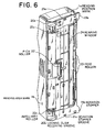
- Fig. 6 is a perspective view thereof.
- a pick roller 22 may be mounted on the bottom surface of the reader unit 1 at a front and center location, while a pair of feed rollers 23 are mounted at right and left positions, respectively, symmetrically relative to the rear center of the reading window 24.
- each of the pick roller 22 and the feed rollers 23 is driven rotationally by the driving motor 8 by way of the driving gear train 9.
- operation of the scanner can be performed automatically by making use of the rotational driving force or torque generated by the electric motor mentioned above.
- the pick roller 22 is usually made of a relatively flexible material of low hardness such as urethane resin. In that case, such situation may occur that the pick roller 22 is collapsed under the gravity of the reader unit and can not support the reader unit.
- an auxiliary rollers 22a made of a material of high hardness which serves for supporting the reader unit 1 so that the pick roller 22 does not apply excessive pressure onto the guide plate or the top surface of the document sheet.
- the auxiliary rollers 22a are disposed outside of the reading region 24 in order to protect the surface of the document sheet 12 against injury, as can be seen in Fig. 4.
- the width of the auxiliary rollers 22a may be increased and mounted in the vicinity of the pick roller 22 so that the auxiliary rollers 22a can rotate freely coaxially with the pick roller 22.
- Figure 7 is a sectional view showing an optical mechanism 25 incorporated in the reader unit 1.
- the reading position is defined at the reading window 24 described hereinbefore by reference to Fig. 4.
- Light rays reflected from the document sheet to be read out and impinging into the optical mechanism through the reading window 24 reflections a number of times at a plurality of mirrors 25a to be collected by a lens 25b and received by a charge coupled device 25c which serves for converting the optical information into an electric signal.
- the paper sheet transportation path and the document sheet transportation path are provided separately for the printer unit and the scanner unit, respectively. Furthermore, it is desirable that the document sheets can be placed at the document sheet feeding tray 6 more easily when compared with the setting of blank paper sheets. To this end, the document sheet transportation path for the scanner unit should be disposed at a position near to the front side of the apparatus, as viewed in Fig. 1A.
- FIG 8 is a schematic sectional view of the printer/scanner combination apparatus in which the two sheet transportation paths (i.e., the paper sheet transportation path and the document sheet transportation path) are provided separately, as mentioned above.
- the printer unit 3 the paper sheet placed as a pile at the paper sheet feeding tray 4 for the printer is automatically transported on a sheet-by-sheet basis along the paper sheet transportation path 30 as indicated by an arrow. After having been printed by a printing head 28, the printed paper sheet is discharged from the printed paper delivery port 5.
- the scanner unit portion having the reading window 24 mounted on the printer unit the document sheet placed on the document sheet feeding tray 6 is automatically fed into the reader unit 1 on a sheet-by-sheet basis.
- the document sheet undergone the reading operation is transported along the document sheet transportation path 31 as indicated by an arrow to be discharged from the document sheet withdrawal port 35.
- the sheet transportation paths for the printer unit and the scanner unit are provided substantially in parallel with each other.
- the document sheet feeding tray 6 disposed at the front side may present an obstacle to the setting or positioning of a pile of paper sheets on the paper sheet feeding tray 4 for the printer.
- the document sheet feeding tray 6 should preferably be so implemented as to be pivotally inclined to the front side, as viewed in Fig. 1 (or to the right-hand side, as viewed in Fig. 8) within a predetermined angular range.
- the printer cover/document sheet guide means 29 serves not only as the cover for the printing mechanism of the printer unit but also as the guide for the document sheet which has undergone the reading operation by the scanner unit. Consequently, the printer cover/document sheet guide means 29 should preferably be so implemented that it can be inclined toward the front side or removed in order to facilitate the maintenance of the printing mechanism.
- Figure 9 is a schematic suctional view of the document sheet feeding tray in the printer/scanner combination apparatus according to the instant embodiment of the invention.
- a document sheet guide 32 and an auxiliary document sheet guide member 33 are disposed in opposition to each other in such orientation that the space defined between the document sheet guide 32 and the auxiliary document sheet guide member 33 becomes narrower gradually toward a document sheet withdrawal port 35.
- the vertical section of the space between the document sheet guide 32 and the auxiliary document sheet guide member 33 presents substantially a wedge-like shape.
- the document sheet guide 32 should preferably be provided with an offset portion 34 in order to prevent the load of all the document sheets piled from being concentrated to the document sheet withdrawal port 35.
- a plurality of such offset portions 34 may be provided although only one offset portion 34 is shown in Fig. 9. Additionally, such offset portion may be provided in the auxiliary document sheet guide member 33 as well. Parenthetically, the offset portion is imparted with a lenient inclination so that the document sheet can slidably move downwardly to the document sheet withdrawal port 35.
- the cable interconnecting the reader unit 1 and the printer unit 3 may preferably be secured to lower side portions of the reader unit 1 and the printer unit 3, respectively, while a cable clamp member for securing the cable to the guide plate may be provided in association with the latter.
- the scanner unit with a base unit such as a printer unit, personal computer, word processor or the like incorporating a printer unit so that the printer unit and the scanner unit can be operated independent of each other.
- the space required for installing the base unit and the scanner unit can be reduced significantly.
- the scanner unit can be easily detached or removed from the base unit and used as an automatically or manually operated handy scanner essentially without need for provision of any additional means.
- the utility efficiency of the printer/scanner combination apparatus can be enhanced remarkably as a whole nevertheless of low manufacturing cost.
Landscapes
- Engineering & Computer Science (AREA)
- Multimedia (AREA)
- Signal Processing (AREA)
- Artificial Intelligence (AREA)
- Computer Vision & Pattern Recognition (AREA)
- Physics & Mathematics (AREA)
- General Physics & Mathematics (AREA)
- Theoretical Computer Science (AREA)
- Facsimiles In General (AREA)
- Facsimile Scanning Arrangements (AREA)
- Image Input (AREA)
- Printers Characterized By Their Purpose (AREA)
Claims (11)
- Un appareil ayant une unité de base (3) pourvue d'un élément séparateur de feuilles (13) et d'un appareil lecteur (1) comprenant un élément de lecture (25), au moins un rouleau de prélèvement (10,22) et un moteur (8) qui entraíne le rouleau de prélèvement (10,22), l'appareil lecteur (1) étant monté de façon amovible sur l'unité de base (3) ;
dans lequel le lecteur (1) lit une feuille qui est délivrée à partir d'une pile de feuilles (12) placée sur l'unité de base (3) par le rouleau de prélèvement (10,22) en coopération avec l'élément séparateur (13) dans un cas où le lecteur (1) est monté sur l'unité de base (3), et
dans lequel le lecteur (1) est mû par le rouleau de prélèvement (10,22) entraíné par le moteur (8) et lit une feuille au moyen de l'élément de lecture (25) dans un cas où le lecteur (1) est détaché de l'unité de base (3). - Un appareil selon la Revendication 1, dans lequel la pile de feuilles (12) est inclinée relativement au plan vertical.
- Un appareil selon la Revendication 1 ou 2,
dans lequel une surface du lecteur (1) sur laquelle est prévu l'élément de lecture (25) fait face à la base (3) dans un cas où le lecteur est monté sur la base (3), de sorte qu'un chemin de transport de feuilles (31) est défini par une surface de la base (3) qui fait face à ladite surface du lecteur, et par la surface du lecteur. - Un appareil selon l'une quelconque des revendications précédentes,
dans lequel un premier chemin de transport de feuilles (31) est formé sensiblement verticalement pour permettre à l'élément de lecture (25) de lire la feuille dans un cas où le lecteur (1) est monté sur la base (3), la base (3) comprend un deuxième chemin de transport de feuilles (30) qui s'étend sensiblement verticalement, la base (3) exécute un traitement pour une feuille qui se déplace le long du deuxième chemin de transport de feuilles, et le premier chemin de transport de feuilles est disposé sensiblement parallèlement au deuxième chemin de transport de feuilles. - Un appareil selon l'une quelconque des revendications précédentes,
dans lequel un rouleau en saillie (22a) est prévu de sorte à faire saillie d'un côté de la surface pour protéger le rouleau de prélèvement (10,22) dans un cas où le lecteur est détaché de l'unité de base pour l'emploi. - Un appareil selon l'une quelconque des revendications précédentes,
dans lequel le rouleau de prélèvement (10,22) de l'appareil lecteur et une surface de lecture de feuilles (24) de l'élément de lecture (25) sont prévus d'un même côté de l'appareil lecteur, et une surface de l'appareil lecteur sur laquelle sont prévus le rouleau de prélèvement et la surface de lecture de feuilles de l'élément de lecture constitue une partie d'un guide de feuilles qui guide la feuille délivrée à partir d'un guide de feuilles de documents (32) dans un cas où le lecteur est monté sur l'unité de base. - Un appareil selon l'une quelconque des revendications précédentes, dans lequel l'élément séparateur de feuilles (13) fait face au rouleau de prélèvement (10,22) de l'appareil lecteur dans un cas où l'appareil lecteur est monté sur l'unité de base.
- Un appareil selon l'une quelconque des revendications précédentes, dans lequel l'unité de base (3) est une imprimante.
- Un appareil selon l'une quelconque des revendications précédentes, qui comprend de plus un mécanisme de transport de feuilles dans un cas où le lecteur est monté sur l'unité de base ;
l'unité de base (3) ayant une partie (16) du mécanisme de transport de feuilles sur une surface extérieure de l'unité de base qui fait face au lecteur (1) ;
et le lecteur (1) ayant l'autre partie (10,11,22,23) du mécanisme de transport de feuilles. - Un appareil selon l'une quelconque des revendications précédentes, dans lequel l'unté de base est pourvue de moyens de montage (18b,19b,20b) de lecteur pour monter le lecteur, et le lecteur est pourvu de moyens d'engagement (18a,19a,20a) pour l'engager avec les moyens de montage de lecteur.
- Un appareil selon l'une quelconque des revendications précédentes, dans lequel l'appareil lecteur (1) comprend de plus un rouleau d'avance (11,23), le lecteur (1) étant mû par le rouleau de prélèvement (10,22), et le rouleau d'avance (11,23) étant entraíné par le moteur (8).
Applications Claiming Priority (3)
| Application Number | Priority Date | Filing Date | Title |
|---|---|---|---|
| JP8292722A JPH10134163A (ja) | 1996-11-05 | 1996-11-05 | スキャナ付き装置 |
| JP29272296 | 1996-11-05 | ||
| EP97308711A EP0840494B1 (fr) | 1996-11-05 | 1997-10-30 | Dispositif équipé d'un unité de balayage amovible |
Related Parent Applications (1)
| Application Number | Title | Priority Date | Filing Date |
|---|---|---|---|
| EP97308711A Division EP0840494B1 (fr) | 1996-11-05 | 1997-10-30 | Dispositif équipé d'un unité de balayage amovible |
Publications (2)
| Publication Number | Publication Date |
|---|---|
| EP1041812A1 EP1041812A1 (fr) | 2000-10-04 |
| EP1041812B1 true EP1041812B1 (fr) | 2004-05-12 |
Family
ID=17785478
Family Applications (8)
| Application Number | Title | Priority Date | Filing Date |
|---|---|---|---|
| EP01201239A Withdrawn EP1150489A3 (fr) | 1996-11-05 | 1997-10-30 | Appareil équipé d'une unité de lecture détachable |
| EP01201240A Withdrawn EP1150484A3 (fr) | 1996-11-05 | 1997-10-30 | Appareil équipé d'une unité de lecture détachable |
| EP00202241A Expired - Lifetime EP1041810B1 (fr) | 1996-11-05 | 1997-10-30 | Dispositif équipé d'une unité de balayage amovible |
| EP03075188A Withdrawn EP1309167A3 (fr) | 1996-11-05 | 1997-10-30 | Dispositif équipé d'une unité de balayage amovible |
| EP97308711A Expired - Lifetime EP0840494B1 (fr) | 1996-11-05 | 1997-10-30 | Dispositif équipé d'un unité de balayage amovible |
| EP00202242A Expired - Lifetime EP1041811B1 (fr) | 1996-11-05 | 1997-10-30 | Dispositif équipé d'une unité de balayage amovible |
| EP00202243A Expired - Lifetime EP1041812B1 (fr) | 1996-11-05 | 1997-10-30 | Dispositif équipé d'une unité de balayage amovible |
| EP00202240A Expired - Lifetime EP1035725B1 (fr) | 1996-11-05 | 1997-10-31 | Dispositif équipé d'une unité de balayage amovible |
Family Applications Before (6)
| Application Number | Title | Priority Date | Filing Date |
|---|---|---|---|
| EP01201239A Withdrawn EP1150489A3 (fr) | 1996-11-05 | 1997-10-30 | Appareil équipé d'une unité de lecture détachable |
| EP01201240A Withdrawn EP1150484A3 (fr) | 1996-11-05 | 1997-10-30 | Appareil équipé d'une unité de lecture détachable |
| EP00202241A Expired - Lifetime EP1041810B1 (fr) | 1996-11-05 | 1997-10-30 | Dispositif équipé d'une unité de balayage amovible |
| EP03075188A Withdrawn EP1309167A3 (fr) | 1996-11-05 | 1997-10-30 | Dispositif équipé d'une unité de balayage amovible |
| EP97308711A Expired - Lifetime EP0840494B1 (fr) | 1996-11-05 | 1997-10-30 | Dispositif équipé d'un unité de balayage amovible |
| EP00202242A Expired - Lifetime EP1041811B1 (fr) | 1996-11-05 | 1997-10-30 | Dispositif équipé d'une unité de balayage amovible |
Family Applications After (1)
| Application Number | Title | Priority Date | Filing Date |
|---|---|---|---|
| EP00202240A Expired - Lifetime EP1035725B1 (fr) | 1996-11-05 | 1997-10-31 | Dispositif équipé d'une unité de balayage amovible |
Country Status (7)
| Country | Link |
|---|---|
| US (2) | US20020036807A1 (fr) |
| EP (8) | EP1150489A3 (fr) |
| JP (1) | JPH10134163A (fr) |
| KR (5) | KR100456179B1 (fr) |
| CN (1) | CN1196538A (fr) |
| DE (5) | DE69729130T2 (fr) |
| TW (1) | TW382675B (fr) |
Families Citing this family (39)
| Publication number | Priority date | Publication date | Assignee | Title |
|---|---|---|---|---|
| JPH10134163A (ja) * | 1996-11-05 | 1998-05-22 | Pfu Ltd | スキャナ付き装置 |
| JP3428444B2 (ja) | 1998-06-30 | 2003-07-22 | 株式会社Pfu | 複合端末装置 |
| CN1196075C (zh) * | 1998-10-05 | 2005-04-06 | 佳能株式会社 | 图象读取装置 |
| US6160642A (en) * | 1998-12-22 | 2000-12-12 | Hewlett-Packard Company | Integrated printer and scanner device |
| WO2001054395A1 (fr) * | 2000-01-19 | 2001-07-26 | Koninklijke Philips Electronics N.V. | Appareil dote d'un dispositif de balayage amovible |
| US6628433B1 (en) * | 2000-07-18 | 2003-09-30 | Eastman Kodak Company | Document scanning system with dockable platen flatbed providing sheet fed and platen scanning functions |
| GB2380083B (en) * | 2001-09-25 | 2006-02-15 | Vidhya Rajeswar Thillainayagam | Scanner-printer |
| US7471425B2 (en) * | 2002-04-23 | 2008-12-30 | Yin-Chun Huang | Scanning method by using sheet feed scanner |
| JP3654288B2 (ja) * | 2002-12-27 | 2005-06-02 | ブラザー工業株式会社 | 可動ユニットのロック機構、位置センサ、可動ユニットの初期設定方法、および画像読取装置 |
| US20050018248A1 (en) * | 2003-03-20 | 2005-01-27 | Kia Silverbrook | Display device having gravity-fed sheet feeder |
| AU2003901297A0 (en) | 2003-03-20 | 2003-04-03 | Silverbrook Research Pty Ltd | Systems and apparatus (fpd001) |
| JP4229771B2 (ja) * | 2003-07-04 | 2009-02-25 | 理想科学工業株式会社 | ポストカード調製機 |
| EP1524836B1 (fr) * | 2003-10-14 | 2017-11-22 | Casio Computer Co., Ltd. | Caméra pour documents et système avec caméra pour documents |
| US7448734B2 (en) | 2004-01-21 | 2008-11-11 | Silverbrook Research Pty Ltd | Inkjet printer cartridge with pagewidth printhead |
| JP4134932B2 (ja) * | 2004-03-31 | 2008-08-20 | ブラザー工業株式会社 | 画像処理装置 |
| CN101945199B (zh) * | 2004-09-21 | 2012-05-30 | 兄弟工业株式会社 | 图像处理设备 |
| KR100565083B1 (ko) * | 2004-10-09 | 2006-03-30 | 삼성전자주식회사 | 화상형성장치 |
| US20070188818A1 (en) * | 2006-02-13 | 2007-08-16 | Eastman Kodak Company | Tiltable document imaging apparatus |
| US7651083B2 (en) | 2006-09-21 | 2010-01-26 | Digital Check Corporation | Conveying apparatus and method |
| JP4815367B2 (ja) * | 2007-03-09 | 2011-11-16 | 株式会社リコー | 画像形成装置 |
| US20100118327A1 (en) * | 2007-07-17 | 2010-05-13 | Christopher Keith Caspar | All-in-One Device with Integrated Monitor |
| CN101594445A (zh) * | 2008-05-30 | 2009-12-02 | 虹光精密工业(苏州)有限公司 | 自动图像处理设备及其进纸装置 |
| WO2011040864A1 (fr) | 2009-10-01 | 2011-04-07 | Scalado Ab | Procédé relatif à des images numériques |
| US20140104661A1 (en) * | 2010-06-22 | 2014-04-17 | Venture Corporation Limited | Integrated Mobile Printer And Scanner |
| USD689865S1 (en) * | 2011-05-30 | 2013-09-17 | Canon Denshi Kabushiki Kaisha | Scanner |
| TWM417261U (en) * | 2011-06-03 | 2011-12-01 | Avision Inc | Apparatus with retractable flatbed scanner |
| USD689866S1 (en) * | 2011-07-15 | 2013-09-17 | Canon Denshi Kabushiki Kaisha | Scanner |
| WO2013012370A1 (fr) * | 2011-07-15 | 2013-01-24 | Scalado Ab | Procédé pour fournir une représentation graphique numérique ajustée d'une vue et appareil approprié |
| DE102011054432A1 (de) * | 2011-10-12 | 2013-04-18 | Dr. Ing. H.C. F. Porsche Aktiengesellschaft | Verbund-Tragstruktur |
| JP5917281B2 (ja) * | 2012-05-07 | 2016-05-11 | キヤノン株式会社 | 画像形成装置 |
| TW201601513A (zh) * | 2014-06-17 | 2016-01-01 | Sintai Optical Shenzhen Co Ltd | 可分離式掃描裝置 |
| JP6515563B2 (ja) | 2015-02-12 | 2019-05-22 | セイコーエプソン株式会社 | 画像読取装置 |
| CN105979111B (zh) * | 2015-03-12 | 2019-09-24 | 精工爱普生株式会社 | 图像读取装置和图像读取系统 |
| CN106210429B (zh) * | 2015-04-29 | 2018-12-11 | 信泰光学(深圳)有限公司 | 藉由可分离式机构来松开卡纸的扫描装置 |
| USD831654S1 (en) * | 2015-12-03 | 2018-10-23 | Avision Inc. | Scanner |
| JP6912755B2 (ja) * | 2017-07-31 | 2021-08-04 | セイコーエプソン株式会社 | 画像読取装置 |
| JP7188263B2 (ja) * | 2019-04-24 | 2022-12-13 | セイコーエプソン株式会社 | 記録装置 |
| JP1647873S (ja) * | 2019-06-19 | 2019-12-16 | スキャナー | |
| CN112312264B (zh) * | 2020-11-05 | 2022-08-09 | 江西立讯智造有限公司 | 一种蓝牙耳机排线扫码装置 |
Family Cites Families (99)
| Publication number | Priority date | Publication date | Assignee | Title |
|---|---|---|---|---|
| US368259A (en) | 1887-08-16 | warren | ||
| JPS56126852A (en) | 1980-03-11 | 1981-10-05 | Canon Inc | Original feeder of copying machine |
| JPS58127753A (ja) | 1982-01-25 | 1983-07-29 | Pilot Pen Co Ltd:The | 可逆性熱白化組成物 |
| SE441795B (sv) | 1984-03-23 | 1985-11-04 | Lyckeaborgs Bruk Ab | Skyddsanordning for att dempa pulsformad hogfrekvent, elektromagnetisk stralnings passage genom en brandskyddande genomforing |
| US4667253A (en) | 1984-11-14 | 1987-05-19 | Chen Philip L | Optical line scanning imaging device |
| JPH0236107B2 (ja) | 1985-07-16 | 1990-08-15 | Takaaki Katayama | Zeiseitainohakaihoho |
| US4677495A (en) | 1985-01-30 | 1987-06-30 | Canon Kabushiki Kaisha | Original reading apparatus |
| JPS6230461A (ja) | 1985-03-30 | 1987-02-09 | Toshiba Corp | フアクシミリ装置 |
| JPS61251356A (ja) | 1985-03-30 | 1986-11-08 | Fujitsu Ltd | 画像入力装置 |
| US4731667A (en) * | 1985-07-15 | 1988-03-15 | Kabushiki Kaisha Toshiba | Image forming apparatus |
| JPS6225556A (ja) | 1985-07-26 | 1987-02-03 | Toshiba Corp | 画像読取り装置 |
| JPS6277953A (ja) | 1985-10-01 | 1987-04-10 | Nec Corp | 発券プリンタ装置 |
| JPS6282869A (ja) | 1985-10-08 | 1987-04-16 | Konishiroku Photo Ind Co Ltd | 移動型記録装置 |
| JPS62173272A (ja) * | 1986-01-28 | 1987-07-30 | Toshiba Corp | 画像形成装置 |
| WO1987007804A1 (fr) * | 1986-06-12 | 1987-12-17 | Casio Computer Co., Ltd. | Copieur de petite dimension |
| JPS6342275A (ja) | 1986-08-07 | 1988-02-23 | Mitsubishi Electric Corp | ハンデイ・イメ−ジリ−ダ |
| JPS6377259A (ja) * | 1986-09-20 | 1988-04-07 | Matsushita Electric Ind Co Ltd | 画像読取り記録装置 |
| JPS6392457U (fr) * | 1986-12-05 | 1988-06-15 | ||
| JPS63197682A (ja) | 1987-02-13 | 1988-08-16 | Hitachi Ltd | パ−ソナルワ−ドプロセツサ |
| JPS6392457A (ja) | 1987-09-09 | 1988-04-22 | Tada Seisakusho:Kk | タイプライターおもちゃ |
| JPH01137661A (ja) | 1987-11-24 | 1989-05-30 | Nec Corp | リードフレーム |
| JPH01137660A (ja) | 1987-11-25 | 1989-05-30 | Hitachi Ltd | 半導体装置 |
| JPH01100564U (fr) | 1987-12-24 | 1989-07-06 | ||
| JPH01235465A (ja) | 1988-03-15 | 1989-09-20 | Nippon Telegr & Teleph Corp <Ntt> | 画像読取装置を有する通信装置 |
| US4989237A (en) | 1988-03-15 | 1991-01-29 | Sharp Kabushiki Kaisha | Image data transmission apparatus |
| JPH0712986B2 (ja) | 1988-04-30 | 1995-02-15 | 新日鐵化学株式会社 | 石綿処理剤 |
| JPH0222958A (ja) | 1988-07-12 | 1990-01-25 | Matsushita Electric Ind Co Ltd | 画像読み取り装置 |
| JP2522526B2 (ja) | 1988-10-05 | 1996-08-07 | シャープ株式会社 | 画像デ―タ伝送装置 |
| JP2864516B2 (ja) | 1989-02-28 | 1999-03-03 | ソニー株式会社 | 文書画像データ読み取り装置 |
| JP2851303B2 (ja) * | 1989-05-18 | 1999-01-27 | 株式会社リコー | プリンター装置 |
| JPH033030A (ja) | 1989-05-31 | 1991-01-09 | Omron Corp | スキャナ付プリンタ装置 |
| JPH07106793B2 (ja) | 1989-09-06 | 1995-11-15 | ダイワ精工株式会社 | 分離給紙装置 |
| US5335090A (en) * | 1989-09-11 | 1994-08-02 | Minolta Camera Kabushiki Kaisha | Image reading apparatus having detachable optical system |
| DE69034024T2 (de) * | 1989-09-18 | 2003-04-17 | Canon Kk | Tintenstrahl-Aufzeichnungsgerät |
| JPH0353069U (fr) | 1989-09-29 | 1991-05-22 | ||
| JP2597196B2 (ja) | 1989-10-06 | 1997-04-02 | 富士写真フイルム株式会社 | 静電写真用液体現像剤 |
| JP2675888B2 (ja) * | 1990-02-13 | 1997-11-12 | キヤノン株式会社 | 情報処理装置 |
| JPH03123363U (fr) | 1990-03-29 | 1991-12-16 | ||
| JPH04117764A (ja) | 1990-09-03 | 1992-04-17 | Sony Corp | 原稿読取装置 |
| JPH04150551A (ja) | 1990-10-13 | 1992-05-25 | Nisca Corp | 画像入力装置 |
| JPH04196746A (ja) | 1990-11-28 | 1992-07-16 | Canon Inc | 自走式ハンディスキャナ |
| JP3066914B2 (ja) | 1991-01-23 | 2000-07-17 | キヤノン株式会社 | 開閉装置 |
| US5166812A (en) | 1991-02-05 | 1992-11-24 | Hewlett-Packard Company | Fax machine with retractable drawer |
| JPH04298159A (ja) | 1991-03-27 | 1992-10-21 | Sony Corp | ファクシミリ装置 |
| JP3044490B2 (ja) * | 1991-04-11 | 2000-05-22 | 株式会社リコー | 画像読取り機能付き画像記録装置 |
| JPH04314256A (ja) | 1991-04-12 | 1992-11-05 | Oki Electric Ind Co Ltd | 画像読取装置 |
| JPH04315362A (ja) * | 1991-04-15 | 1992-11-06 | Canon Inc | 携帯型画像読取装置およびその原稿搬送装置 |
| US5153736A (en) * | 1991-05-20 | 1992-10-06 | Xerox Corporation | Toggling sheet transport and registration system |
| JPH04135065U (ja) * | 1991-06-07 | 1992-12-16 | 旭光学工業株式会社 | 電子写真式フアクシミリ装置 |
| EP0548374B1 (fr) * | 1991-07-09 | 1998-10-07 | Oki Electric Industry Company, Limited | Imprimante equipee d'un lecteur d'image |
| JP2557796Y2 (ja) | 1991-07-09 | 1997-12-17 | 沖電気工業株式会社 | 画像読取装置付き印刷装置 |
| JP2693660B2 (ja) | 1991-07-11 | 1997-12-24 | 立川ブラインド工業株式会社 | 採光調節装置の障害物検知停止装置 |
| US5359435A (en) * | 1991-08-30 | 1994-10-25 | Canon Kabushiki Kaisha | Facsimile apparatus |
| US5182450A (en) * | 1991-11-06 | 1993-01-26 | Primax Electronics Ltd. | Handheld image scanner with automatic movement control |
| JP3096996B2 (ja) | 1992-05-06 | 2000-10-10 | 株式会社リコー | 画像記録装置 |
| US5710634A (en) * | 1992-06-03 | 1998-01-20 | Canon Kabushiki Kaisha | Output apparatus and method for reading and recording |
| JPH06164834A (ja) | 1992-11-14 | 1994-06-10 | Nisca Corp | 画像読み取り装置 |
| TW225020B (fr) | 1992-08-11 | 1994-06-11 | Nisca Corp | |
| JPH0662177A (ja) * | 1992-08-11 | 1994-03-04 | Nisca Corp | 画像読み取り装置 |
| JPH0662181A (ja) | 1992-08-11 | 1994-03-04 | Nisca Corp | 画像読み取り装置 |
| JPH0662178A (ja) | 1992-08-11 | 1994-03-04 | Nisca Corp | 画像読み取り装置 |
| JP3137149B2 (ja) | 1992-09-16 | 2001-02-19 | 株式会社東芝 | ファクシミリ装置 |
| JPH06103208A (ja) | 1992-09-18 | 1994-04-15 | Canon Inc | スキャンサーバシステム |
| JP3109952B2 (ja) * | 1993-04-21 | 2000-11-20 | キヤノン株式会社 | 記録装置 |
| JPH0776122A (ja) * | 1993-06-24 | 1995-03-20 | Brother Ind Ltd | 画像形成装置 |
| JP2848429B2 (ja) | 1993-07-30 | 1999-01-20 | 松下電送システム株式会社 | ファクシミリ装置 |
| JP3231497B2 (ja) | 1993-08-02 | 2001-11-19 | 松下電送システム株式会社 | 読取装置およびこれを用いたファクシミリ装置 |
| US5559609A (en) * | 1993-07-30 | 1996-09-24 | Matsushita Graphic Communication Systems, Inc. | Facsimile transceiver |
| JPH0746368A (ja) | 1993-08-03 | 1995-02-14 | Canon Inc | ファクシミリ装置 |
| DE69417319T2 (de) * | 1993-08-30 | 1999-07-15 | Hewlett Packard Co | Bildabtastkopf für einen thermischen Tintenstrahldrucker |
| US5532825A (en) * | 1993-08-30 | 1996-07-02 | Hewlett-Packard Company | Add-on scanner for existing ink jet printer |
| JP3382365B2 (ja) * | 1993-08-31 | 2003-03-04 | キヤノン株式会社 | インクジェット記録装置および画像形成装置 |
| US5738454A (en) | 1993-10-29 | 1998-04-14 | Hewlett-Packard Company | Multiple-function printer with common output path mechanism with floating guide ribs to accommodate media and documents of different thickness |
| US5651623A (en) | 1993-10-29 | 1997-07-29 | Hewlett-Packard Company | Multiple-function printer with common feeder/output path mechanisms and method of operation |
| US5727890A (en) | 1993-10-29 | 1998-03-17 | Hewlett-Packard Company | Multiple-function printer with common mounting chassis feeder/output path mechanisms |
| DE69404801T2 (de) | 1993-10-29 | 1998-03-12 | Hewlett Packard Co | Drucker für Mehrfachfunktionen mit gemeinsamen Ein/Ausgabeweg |
| JPH07135550A (ja) | 1993-11-10 | 1995-05-23 | Canon Inc | 入出力装置 |
| US5412205A (en) | 1993-11-18 | 1995-05-02 | Logitech, Inc. | Scanner with a wing-shaped fluorescent tube housing and dual-faceted scan window |
| US5579129A (en) * | 1993-12-17 | 1996-11-26 | Canon Kabushiki Kaisha | Original reading apparatus and information processing apparatus with original reading apparatus |
| JP3347858B2 (ja) | 1994-01-26 | 2002-11-20 | 株式会社リコー | 原稿搬送装置およびそれを搭載した原稿読取装置 |
| US5475503A (en) | 1994-02-08 | 1995-12-12 | Logitech, Inc. | Roller for optical scanner |
| JPH07250222A (ja) | 1994-03-10 | 1995-09-26 | Sony Corp | カラーハンディスキャナ |
| JP3097450B2 (ja) * | 1994-04-25 | 2000-10-10 | ブラザー工業株式会社 | 記録装置およびファクシミリ装置 |
| JP3007793B2 (ja) * | 1994-05-16 | 2000-02-07 | シャープ株式会社 | 情報処理装置 |
| JP3402847B2 (ja) * | 1994-05-24 | 2003-05-06 | キヤノン株式会社 | 画像情報処理装置及びプリンタ装置 |
| JP3604767B2 (ja) * | 1994-06-01 | 2004-12-22 | キヤノン株式会社 | 画像情報処理装置 |
| JPH07154530A (ja) | 1994-06-29 | 1995-06-16 | Canon Inc | 画像形成装置 |
| US5567068A (en) * | 1994-06-30 | 1996-10-22 | Matsushita Electric Industrial Co., Ltd. | Multifunction printer |
| JPH08149257A (ja) * | 1994-11-24 | 1996-06-07 | Nikon Corp | 画像入力装置 |
| JP3391920B2 (ja) * | 1994-12-01 | 2003-03-31 | キヤノン株式会社 | ファクシミリ装置 |
| US5711516A (en) | 1995-07-05 | 1998-01-27 | Storm Technology Inc. | Sheet feeder having sloping sheet support side for use with detachable image scanner |
| US5893006A (en) * | 1995-07-31 | 1999-04-06 | Canon Kabushiki Kaisha | Process cartridge detectably mountable to image forming apparatus and image forming apparatus using same |
| US6247784B1 (en) * | 1995-09-08 | 2001-06-19 | Canon Kabushiki Kaisha | Ink jet cartridge replacement control |
| JP3132993B2 (ja) * | 1995-10-05 | 2001-02-05 | 株式会社ピーエフユー | 画像読取装置 |
| JPH1020595A (ja) * | 1996-06-28 | 1998-01-23 | Canon Inc | 電子写真画像形成装置 |
| US5896206A (en) * | 1996-09-13 | 1999-04-20 | Hewlett-Packard Company | Combination printer and scanner having single paper path with pinch rollers actuated by pen door |
| JPH10134163A (ja) * | 1996-11-05 | 1998-05-22 | Pfu Ltd | スキャナ付き装置 |
| JPH10150513A (ja) * | 1996-11-15 | 1998-06-02 | Mita Ind Co Ltd | 画像形成装置 |
| US5954326A (en) * | 1997-11-14 | 1999-09-21 | Hewlett-Packard Company | Three state shifting device for multi-function office equipment |
-
1996
- 1996-11-05 JP JP8292722A patent/JPH10134163A/ja active Pending
-
1997
- 1997-10-30 DE DE69729130T patent/DE69729130T2/de not_active Expired - Fee Related
- 1997-10-30 DE DE69724215T patent/DE69724215T2/de not_active Expired - Fee Related
- 1997-10-30 EP EP01201239A patent/EP1150489A3/fr not_active Withdrawn
- 1997-10-30 EP EP01201240A patent/EP1150484A3/fr not_active Withdrawn
- 1997-10-30 EP EP00202241A patent/EP1041810B1/fr not_active Expired - Lifetime
- 1997-10-30 EP EP03075188A patent/EP1309167A3/fr not_active Withdrawn
- 1997-10-30 EP EP97308711A patent/EP0840494B1/fr not_active Expired - Lifetime
- 1997-10-30 EP EP00202242A patent/EP1041811B1/fr not_active Expired - Lifetime
- 1997-10-30 EP EP00202243A patent/EP1041812B1/fr not_active Expired - Lifetime
- 1997-10-30 DE DE69721081T patent/DE69721081T2/de not_active Expired - Fee Related
- 1997-10-30 DE DE69721080T patent/DE69721080T2/de not_active Expired - Fee Related
- 1997-10-31 DE DE69739022T patent/DE69739022D1/de not_active Expired - Fee Related
- 1997-10-31 EP EP00202240A patent/EP1035725B1/fr not_active Expired - Lifetime
- 1997-11-04 TW TW086116383A patent/TW382675B/zh not_active IP Right Cessation
- 1997-11-04 US US08/964,257 patent/US20020036807A1/en not_active Abandoned
- 1997-11-05 KR KR1019970058203A patent/KR100456179B1/ko not_active IP Right Cessation
- 1997-11-05 CN CN97109395A patent/CN1196538A/zh active Pending
-
2001
- 2001-04-23 KR KR1020010021715A patent/KR100456652B1/ko not_active IP Right Cessation
- 2001-04-23 KR KR1020010021716A patent/KR100456653B1/ko not_active IP Right Cessation
- 2001-04-23 KR KR1020010021714A patent/KR100456651B1/ko not_active IP Right Cessation
- 2001-04-23 KR KR1020010021717A patent/KR100456654B1/ko not_active IP Right Cessation
- 2001-06-14 US US09/881,529 patent/US7133169B2/en not_active Expired - Fee Related
Also Published As
Similar Documents
| Publication | Publication Date | Title |
|---|---|---|
| EP1041812B1 (fr) | Dispositif équipé d'une unité de balayage amovible | |
| EP2306698B1 (fr) | Appareil de traitement d'image | |
| US7088475B1 (en) | Image reading device | |
| US7584950B2 (en) | Image forming apparatus and sheet feeding cassette | |
| JP4581711B2 (ja) | 画像記録装置 | |
| US7379218B1 (en) | Apparatus equipped with removable scanner unit | |
| US6633414B1 (en) | Apparatus having a scanner | |
| EP1950158A1 (fr) | Dispositif d enregistrement d image | |
| US5969831A (en) | Image reading system having automatic document feeding device | |
| US7184182B1 (en) | Image recording device | |
| JP2000341484A (ja) | スキャナ付き装置 | |
| JP3289767B2 (ja) | プリンタ・スキャナ複合装置 | |
| JP2000341483A (ja) | スキャナ付き装置 | |
| JP2000341485A (ja) | スキャナ付き装置 | |
| JP2003110809A (ja) | スキャナ付き装置 | |
| JP4324003B2 (ja) | シート材供給装置および記録装置 | |
| JP2021170732A (ja) | 画像処理装置 | |
| JP5942479B2 (ja) | 画像形成装置 | |
| JPH0479188B2 (fr) | ||
| JPH06105073A (ja) | 画情報読取り装置 |
Legal Events
| Date | Code | Title | Description |
|---|---|---|---|
| PUAI | Public reference made under article 153(3) epc to a published international application that has entered the european phase |
Free format text: ORIGINAL CODE: 0009012 |
|
| 17P | Request for examination filed |
Effective date: 20000628 |
|
| AC | Divisional application: reference to earlier application |
Ref document number: 840494 Country of ref document: EP |
|
| AK | Designated contracting states |
Kind code of ref document: A1 Designated state(s): DE FR GB |
|
| AKX | Designation fees paid |
Free format text: DE FR GB |
|
| 17Q | First examination report despatched |
Effective date: 20010531 |
|
| GRAP | Despatch of communication of intention to grant a patent |
Free format text: ORIGINAL CODE: EPIDOSNIGR1 |
|
| GRAS | Grant fee paid |
Free format text: ORIGINAL CODE: EPIDOSNIGR3 |
|
| GRAA | (expected) grant |
Free format text: ORIGINAL CODE: 0009210 |
|
| AC | Divisional application: reference to earlier application |
Ref document number: 0840494 Country of ref document: EP Kind code of ref document: P |
|
| AK | Designated contracting states |
Kind code of ref document: B1 Designated state(s): DE FR GB |
|
| PG25 | Lapsed in a contracting state [announced via postgrant information from national office to epo] |
Ref country code: FR Free format text: LAPSE BECAUSE OF FAILURE TO SUBMIT A TRANSLATION OF THE DESCRIPTION OR TO PAY THE FEE WITHIN THE PRESCRIBED TIME-LIMIT Effective date: 20040512 |
|
| REG | Reference to a national code |
Ref country code: GB Ref legal event code: FG4D |
|
| REF | Corresponds to: |
Ref document number: 69729130 Country of ref document: DE Date of ref document: 20040617 Kind code of ref document: P |
|
| PG25 | Lapsed in a contracting state [announced via postgrant information from national office to epo] |
Ref country code: GB Free format text: LAPSE BECAUSE OF NON-PAYMENT OF DUE FEES Effective date: 20041030 |
|
| PLBE | No opposition filed within time limit |
Free format text: ORIGINAL CODE: 0009261 |
|
| STAA | Information on the status of an ep patent application or granted ep patent |
Free format text: STATUS: NO OPPOSITION FILED WITHIN TIME LIMIT |
|
| 26N | No opposition filed |
Effective date: 20050215 |
|
| EN | Fr: translation not filed | ||
| GBPC | Gb: european patent ceased through non-payment of renewal fee |
Effective date: 20041030 |
|
| PGFP | Annual fee paid to national office [announced via postgrant information from national office to epo] |
Ref country code: DE Payment date: 20081027 Year of fee payment: 12 |
|
| PG25 | Lapsed in a contracting state [announced via postgrant information from national office to epo] |
Ref country code: DE Free format text: LAPSE BECAUSE OF NON-PAYMENT OF DUE FEES Effective date: 20100501 |