EP1041260A2 - Brennkraftmaschine - Google Patents
Brennkraftmaschine Download PDFInfo
- Publication number
- EP1041260A2 EP1041260A2 EP00103445A EP00103445A EP1041260A2 EP 1041260 A2 EP1041260 A2 EP 1041260A2 EP 00103445 A EP00103445 A EP 00103445A EP 00103445 A EP00103445 A EP 00103445A EP 1041260 A2 EP1041260 A2 EP 1041260A2
- Authority
- EP
- European Patent Office
- Prior art keywords
- internal combustion
- combustion engine
- crankcase
- pump
- cylinder
- Prior art date
- Legal status (The legal status is an assumption and is not a legal conclusion. Google has not performed a legal analysis and makes no representation as to the accuracy of the status listed.)
- Granted
Links
- 238000002485 combustion reaction Methods 0.000 title claims abstract description 38
- XLYOFNOQVPJJNP-UHFFFAOYSA-N water Substances O XLYOFNOQVPJJNP-UHFFFAOYSA-N 0.000 claims abstract description 27
- 239000000498 cooling water Substances 0.000 claims description 22
- 238000001816 cooling Methods 0.000 claims description 9
- 238000000034 method Methods 0.000 claims 3
- 239000012530 fluid Substances 0.000 claims 1
- 239000000446 fuel Substances 0.000 claims 1
- 238000009434 installation Methods 0.000 description 5
- 239000002826 coolant Substances 0.000 description 4
- 239000013505 freshwater Substances 0.000 description 2
- 230000000694 effects Effects 0.000 description 1
- 239000000463 material Substances 0.000 description 1
Images

Classifications
-
- F—MECHANICAL ENGINEERING; LIGHTING; HEATING; WEAPONS; BLASTING
- F02—COMBUSTION ENGINES; HOT-GAS OR COMBUSTION-PRODUCT ENGINE PLANTS
- F02B—INTERNAL-COMBUSTION PISTON ENGINES; COMBUSTION ENGINES IN GENERAL
- F02B75/00—Other engines
- F02B75/16—Engines characterised by number of cylinders, e.g. single-cylinder engines
- F02B75/18—Multi-cylinder engines
- F02B75/22—Multi-cylinder engines with cylinders in V, fan, or star arrangement
- F02B75/224—Multi-cylinder engines with cylinders in V, fan, or star arrangement with cylinders in fan arrangement
-
- F—MECHANICAL ENGINEERING; LIGHTING; HEATING; WEAPONS; BLASTING
- F01—MACHINES OR ENGINES IN GENERAL; ENGINE PLANTS IN GENERAL; STEAM ENGINES
- F01P—COOLING OF MACHINES OR ENGINES IN GENERAL; COOLING OF INTERNAL-COMBUSTION ENGINES
- F01P5/00—Pumping cooling-air or liquid coolants
- F01P5/10—Pumping liquid coolant; Arrangements of coolant pumps
-
- F—MECHANICAL ENGINEERING; LIGHTING; HEATING; WEAPONS; BLASTING
- F02—COMBUSTION ENGINES; HOT-GAS OR COMBUSTION-PRODUCT ENGINE PLANTS
- F02B—INTERNAL-COMBUSTION PISTON ENGINES; COMBUSTION ENGINES IN GENERAL
- F02B67/00—Engines characterised by the arrangement of auxiliary apparatus not being otherwise provided for, e.g. the apparatus having different functions; Driving auxiliary apparatus from engines, not otherwise provided for
- F02B67/04—Engines characterised by the arrangement of auxiliary apparatus not being otherwise provided for, e.g. the apparatus having different functions; Driving auxiliary apparatus from engines, not otherwise provided for of mechanically-driven auxiliary apparatus
-
- F—MECHANICAL ENGINEERING; LIGHTING; HEATING; WEAPONS; BLASTING
- F01—MACHINES OR ENGINES IN GENERAL; ENGINE PLANTS IN GENERAL; STEAM ENGINES
- F01P—COOLING OF MACHINES OR ENGINES IN GENERAL; COOLING OF INTERNAL-COMBUSTION ENGINES
- F01P3/00—Liquid cooling
- F01P3/02—Arrangements for cooling cylinders or cylinder heads
- F01P2003/021—Cooling cylinders
-
- F—MECHANICAL ENGINEERING; LIGHTING; HEATING; WEAPONS; BLASTING
- F01—MACHINES OR ENGINES IN GENERAL; ENGINE PLANTS IN GENERAL; STEAM ENGINES
- F01P—COOLING OF MACHINES OR ENGINES IN GENERAL; COOLING OF INTERNAL-COMBUSTION ENGINES
- F01P3/00—Liquid cooling
- F01P3/02—Arrangements for cooling cylinders or cylinder heads
- F01P2003/027—Cooling cylinders and cylinder heads in parallel
Definitions
- the invention relates to an internal combustion engine according to the preamble of claim 1 out.
- Reciprocating engines are 3 cylinder banks, each with 6 cylinders arranged in series V-shaped in a crankcase.
- a water pump which is connected to a Front side of the crankcase is arranged and which has two outlet channels to which Corresponding cooling channels are connected to the individual cylinder banks. It is a first outlet channel of the water pump with cooling channels to the left outer Cylinder bank and via a branch with a cooling channel to the rear of the pump remote Part of the middle cylinder bank connected.
- the second outlet channel of the water pump is on corresponding cooling channels of the outer cylinder bank on the right and via a Branch to a cooling duct to supply the front part of the pump near the pump middle cylinder bank connected.
- the return or discharge of the cooling water from the The motor is carried out via external return manifolds.
- the known internal combustion engine has the disadvantage that the Water pump to supply the unit with cooling water outside of the actual one Dimensions of the crankcase is also attached to this and so the installation dimensions the internal combustion engine enlarged. Because when using such internal combustion engines as the engine of a vehicle, especially a passenger car, but only a limited one Installation space is available, the known internal combustion engines suffice the current Requirements for modern internal combustion engines no longer.
- the invention is therefore based on the object of an internal combustion engine Reciprocating engine design with cylinder banks arranged in a V-shape relative to one another in this way to further develop that necessary additional units do not affect the overall installation space of the engine significantly enlarge.
- the internal combustion engine according to the invention with the characterizing features of Claim 1 has the advantage over the known solutions that the Additional units, especially the pumps for the coolant in the existing ones Installation space is integrated into the internal combustion engine and so no additional space is required cause.
- this is exemplified by an internal combustion engine with three V-shapes cylinder banks arranged with respect to one another, each having six cylinders, two Pumps designed as water pumps in the V-shaped spaces between the
- more pumps e.g. four Pumps or only a single pump may be provided.
- other delivery units e.g. oil pump or similar
- for operating materials of the Internal combustion engine or this in combination with the water pumps in the V-shaped Insert spaces e.g. oil pump or similar
- Another advantage is the direct drive of the pumps, which is not described in detail achieved via a common center drive on the internal combustion engine, this preferably pure gear drive in the middle of the crankcase in the direction thereof Longitudinal extension is arranged. This is advantageously done by dividing the inner central cylinder bank possible, which creates the necessary space for one such center drive is created.
- the central pump drive has one Saving space for an additional drive, e.g. a belt drive.
- the cooling water is supplied to the rear part of the middle cylinder bank facing away from the pumps is now more advantageous Way across the adjacent outer cylinder banks.
- the external cylinder banks are flowed through and at corresponding The cooling water then flows out of these branches into the rear part of the branches middle cylinder bank.
- the cooling water channels are between the water pumps and all cylinder banks advantageously integrated into the crankcase, so that on external lines can be dispensed with.
- the water pumps are preferably constructed in three stages, with the respective modified Bucket wheel geometry realized different pressure increase levels during the conveyance become.
- the exemplary embodiment shows an 18-cylinder engine with three cylinder banks of six each Cylinders in series, the cylinder banks being arranged in a V-shape with respect to one another.
- FIG. 1 shows a simplified view of the front of the internal combustion engine with the representation of the arrangement of the water pumps
- Figure 2 is a plan view of the Crankcase with the representation of the arrangement of the water pumps
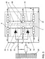
- Figure 3 a Schematic representation of the cooling water circuit of the invention Internal combustion engine.
- the internal combustion engine of the reciprocating piston engine type shown in simplified form in FIG has a crankcase 1, which in a known manner by a not shown Oil pan is closed down and which three V-shaped to each other Cylinder banks with six cylinders in a row.
- a crankcase 1 which in a known manner by a not shown Oil pan is closed down and which three V-shaped to each other Cylinder banks with six cylinders in a row.
- One forms in the front view outer cylinder bank on the left a first cylinder bank 3, a middle, inner one A second cylinder bank 5 and an outer cylinder bank on the right one third cylinder bank 7.
- the cylinder banks 3,5,7 of the crankcase 1 are by means of corresponding cylinder heads 9 and cylinder head covers 11 placed thereon in a known manner Closed way.
- the individual cylinder banks 3, 5, 7 have an angle of preferably 60 ° to them each adjacent cylinder banks, so that there is a gap between two adjacent cylinder banks each result in a V-shaped space.
- V-shaped spaces 13 and 15 between the cylinder banks 3,5,7 is in each case a coolant, preferably water-pump used, one in the first Intermediate space 13 arranged pump a first water pump 17 and one in the second Gap 15 arranged pump forms a second water pump 19.
- a coolant preferably water-pump used, one in the first Intermediate space 13 arranged pump a first water pump 17 and one in the second Gap 15 arranged pump forms a second water pump 19.
- These water pumps 17, 19 are designed as three-stage pumps and by means of a flange, not shown, perpendicular to its axis on a corresponding Receiving surface of the crankcase 1 screwed tight, being within the Mounting flange, the delivery opening of the water pumps 17, 19 is arranged, which in a corresponding inlet space opens into the crankcase 1.
- the feeder Fresh water takes place here, as can also be seen from the arrows in FIG axial inlet opening on the end faces.
- the pumps 17, 19 do not protrude beyond the Installation space of the crankcase 1 also.
- the top view of the crankcase 1 shown in FIG. 2 shows a central one Recess 21 in the crankcase 1 through which the inner second cylinder bank 5 is divided between the third and fourth cylinders, so that a front, the Water pumps 17, 19 adjacent part 5A of the second cylinder bank 5 and a rear, the pumps 17, 19 further part 5B of the second cylinder bank 5 is formed.
- central recess 21 is a control drive, not shown Internal combustion engine arranged, which advantageously also the common drive of the water pumps 17, 19 arranged adjacent to one another via a drives the corresponding gear train rotating.
- the first water pump 17 conveys from a cooler 23 via an inlet line 22 cold water via a branch in the front part 5A of the central cylinder bank 5, which flows around the three cylinders on the left and flows out into a return line 24. Another part of the cooling water delivered by the first pump 17 flows into the first Cylinder bank 3, with part of the cooling water there via the three cylinders on the left the return line 24 flows out and another part to the right three cylinders flows within the first cylinder bank 3.
- This cooling flow divides again, whereby a part flows into a pump-remote connection of the return line 24 and another Partial cooling water flow via a connecting line 25 in the rear part 5B remote from the pump flows into the middle cylinder bank 5 and cools the right-hand three cylinders there flows around, before it also in a pump remote connection of the return line 24th flows in.
- the return line 24 opens with the interposition of a thermostat 26 in the Cooler 23 or after a corresponding switching of the thermostat when cold Internal combustion engine again directly into the feed line 22.
- the second water pump 19 analogously from the inlet line 22 cold water in the pump-near front part 5A of the central cylinder bank 5, where this, the left three cylinders flowing out again in the return line 24.
- the second water pump 19 also pumps fresh water into the third cylinder bank 7, where a Partial flow after flowing along the three cylinders on the left also back into the Return line 24 exits.
- Another part of the cooling water flows inside the third cylinder bank 7 to the right, flows around the right-hand three cylinders and occurs a remote connection to the pump in the return line 24.
- a partial flow of right-hand flow of cooling water also enters via a connecting line 25 the rear, pump-remote part 5B of the central cylinder bank 5 and flows there along the three cylinders on the right via a connection remote from the pump into the return line 24 from.
Landscapes
- Engineering & Computer Science (AREA)
- Chemical & Material Sciences (AREA)
- Combustion & Propulsion (AREA)
- Mechanical Engineering (AREA)
- General Engineering & Computer Science (AREA)
- Cylinder Crankcases Of Internal Combustion Engines (AREA)
- Lubrication Of Internal Combustion Engines (AREA)
- Valve Device For Special Equipments (AREA)
- Valve-Gear Or Valve Arrangements (AREA)
Abstract
Description
Claims (12)
- Brennkraftmaschine der Hubkolbenmotorenbauart mit wenigstens zwei V-förmig zueinander angeordneten Zylinderbänken (3,5,7), die an einem gemeinsamen Kurbelgehäuse (1) angeordnet sind und mit wenigstens einer, einen Betriebsstoff der Brennkraftmaschine fördernden Pumpe (17,19), die am Kurbelgehäuse (1) angeordnet ist, dadurch gekennzeichnet, daß die Pumpe (17,19) in einem zwischen den Zylinderbänken (3,5,7) gebildeten V-förmigen Zwischenraum (13,15) eingesetzt und dort direkt am Kurbelgehäuse (1) befestigt ist.
- Brennkraftmaschine nach Anspruch 1, dadurch gekennzeichnet, daß vorzugsweise zwei Pumpen (17,19) vorgesehen sind, die jeweils in einem der V-förmigen Zwischenräume (13,15) der Zylinderbänke (3,5,7) angeordnet sind und daß der geförderte Betriebsstoff Kühlwasser ist.
- Brennkraftmaschine nach Anspruch 2, dadurch gekennzeichnet, daß die Wasserpumpen (17,19) in Längsrichtung des Kurbelgehäuses (1) axial nebeneinander in jeweils einer der V-förmigen Zwischenräume (13,15) angeordnet sind.
- Brennkraftmaschine nach Anspruch 1, dadurch gekennzeichnet, daß die in den V-förmigen Zwischenraum (13,15) der Zylinderbänke (3,5,7) eingesetzte Pumpe (17,19) vollständig in die Außenabmessungen des Kurbelgehäuses (1) eintaucht.
- Brennkraftmaschine nach Anspruch 1, dadurch gekennzeichnet, daß die ein Betriebsmittel, vorzugsweise Wasser fördernde Pumpe (17,19) mehrstufig, vorzugsweise 3-stufig ausgebildet ist.
- Brennkraftmaschine nach Anspruch 1, dadurch gekennzeichnet, daß das Fördermedium der Pumpe (17,19) stirnseitig zugeführt wird und über eine senkrecht zur Pumpenachse liegende Förderöffnung in eine entsprechene Öffnung am Kurbelgehäuse (1) eingespeist wird.
- Brennkraftmaschine nach Anspruch 1, dadurch gekennzeichnet, daß die in den V-förmigen Zwischenräumen (13,15) angeordneten Pumpen (17,19) über einen mittig im Kurbelgehäuse (1) angeordneten Antrieb rotierend angetrieben werden.
- Brennkraftmaschine nach Anspruch 7, dadurch gekennzeichnet, daß sämtliche Pumpen (17,19) in den V-förmigen Zwischenräumen (13,15) von einem gemeinsamen Antrieb angetrieben werden.
- Brennkraftmaschine nach Anspruch 1, dadurch gekennzeichnet, daß drei jeweils V-förmig zueinander angeordnete Zylinderbänke (3,5,7) mit jeweils sechs Zylindern vorgesehen sind.
- Verfahren zur Wasserkühlung einer Brennkraftmaschine mit wenigstens zwei V-förmig zueinander angeordneten Zylinderbänken, die an einem gemeinsamen Kurbelgehäuse (1) angeordnet sind und von wenigstens einer Pumpe (17,19) mit Kühlwasser versorgt werden, dadurch gekennzeichnet, daß wenigstens ein Teil des geförderten Kühlwassers von einer ersten Zylinderbank (3) in eine benachbarte zweite Zylinderbank (5) überströmt.
- Verfahren nach Anspruch 10, dadurch gekennzeichnet, daß drei V-förmig zueinander angeordnete Zylinderbänke (3,5,7) vorgesehen sind, wobei eine innenliegende Zylinderbank (5) von wenigstens einer außenliegenden Zylinderbank (3,7) über entsprechende Verbindungakanäle (25) mit Kühlwasser versorgt wird.
- Verfahren nach Anspruch 11, dadurch gekennzeichnet, daß die innenliegende Zylinderbank (5) zwischen zwei benachbarten Zylinderbohrungen geteilt ist und daß die Kühlwasserzufuhr in einen, den Kühlwasserpumpen (17,19) abgewandten hinteren Teil (5B) der geteilten Zylinderbank (5) über einen Verbindungskanal (25) aus wenigstens einer benachbarten Zylinderbank (3,7) erfolgt.
Applications Claiming Priority (2)
| Application Number | Priority Date | Filing Date | Title |
|---|---|---|---|
| DE19909619 | 1999-03-05 | ||
| DE19909619A DE19909619A1 (de) | 1999-03-05 | 1999-03-05 | Brennkraftmaschine |
Publications (3)
| Publication Number | Publication Date |
|---|---|
| EP1041260A2 true EP1041260A2 (de) | 2000-10-04 |
| EP1041260A3 EP1041260A3 (de) | 2001-11-14 |
| EP1041260B1 EP1041260B1 (de) | 2004-11-24 |
Family
ID=7899763
Family Applications (1)
| Application Number | Title | Priority Date | Filing Date |
|---|---|---|---|
| EP00103445A Expired - Lifetime EP1041260B1 (de) | 1999-03-05 | 2000-02-28 | Brennkraftmaschine |
Country Status (3)
| Country | Link |
|---|---|
| EP (1) | EP1041260B1 (de) |
| AT (1) | ATE283421T1 (de) |
| DE (2) | DE19909619A1 (de) |
Families Citing this family (2)
| Publication number | Priority date | Publication date | Assignee | Title |
|---|---|---|---|---|
| DE10052121B4 (de) * | 2000-10-19 | 2016-03-31 | Volkswagen Ag | Brennkraftmaschine mit wenigstens zwei Motorsteuergeräten |
| DE102007021237A1 (de) * | 2007-05-07 | 2008-11-13 | Bayerische Motoren Werke Aktiengesellschaft | Brennkraftmaschine mit mehreren schmiermittelversorgten Zylinderköpfen sowie Verfahren zur Steuerung einer Pumpe einer Brennkraftmaschine |
Citations (1)
| Publication number | Priority date | Publication date | Assignee | Title |
|---|---|---|---|---|
| GB337475A (en) | 1929-08-06 | 1930-11-06 | Giustino Cattaneo | Improvement in the water-cooling system for internal combustion engines with w-arranged cylinders |
Family Cites Families (4)
| Publication number | Priority date | Publication date | Assignee | Title |
|---|---|---|---|---|
| US1407336A (en) * | 1918-07-15 | 1922-02-21 | Harvey J Sallee | Internal-combustion engine |
| GB151534A (en) * | 1920-03-02 | 1920-09-30 | Bernard Robert Bellanger | Improvements in internal combustion engines |
| US4054108A (en) * | 1976-08-02 | 1977-10-18 | General Motors Corporation | Internal combustion engine |
| DE4032590A1 (de) * | 1990-10-13 | 1992-04-16 | Porsche Ag | Hubkolbenmotor mit zwei v-foermig angeordneten zylinderreihen |
-
1999
- 1999-03-05 DE DE19909619A patent/DE19909619A1/de not_active Withdrawn
-
2000
- 2000-02-28 AT AT00103445T patent/ATE283421T1/de not_active IP Right Cessation
- 2000-02-28 DE DE50008718T patent/DE50008718D1/de not_active Expired - Fee Related
- 2000-02-28 EP EP00103445A patent/EP1041260B1/de not_active Expired - Lifetime
Patent Citations (1)
| Publication number | Priority date | Publication date | Assignee | Title |
|---|---|---|---|---|
| GB337475A (en) | 1929-08-06 | 1930-11-06 | Giustino Cattaneo | Improvement in the water-cooling system for internal combustion engines with w-arranged cylinders |
Also Published As
| Publication number | Publication date |
|---|---|
| DE50008718D1 (de) | 2004-12-30 |
| DE19909619A1 (de) | 2000-09-07 |
| ATE283421T1 (de) | 2004-12-15 |
| EP1041260B1 (de) | 2004-11-24 |
| EP1041260A3 (de) | 2001-11-14 |
Similar Documents
| Publication | Publication Date | Title |
|---|---|---|
| DE102007062347B4 (de) | Kühlanordnung für einen Zylinderkopf einer Brennkraftmaschine | |
| DE2950905A1 (de) | Kuehleinrichtung sowie zylinderkopf fuer verbrennungsmotor | |
| EP0232467A2 (de) | Mehrzylindrige Brennkraftmaschine | |
| DE4292209B4 (de) | Anordnung für eine Kraftstoffleitung in einem Verbrennungsmotor | |
| DE102004032653A1 (de) | Zylinderkopfstruktur eines Motors | |
| DE10127219A1 (de) | Kühlanlage für einen Verbrennungsmotor | |
| EP1751411B1 (de) | Optimierte ölkühlung für eine brennkraftmaschine | |
| DE102018116973A1 (de) | Zylinderkopf und Kurbelgehäuse für eine Brennkraftmaschine | |
| WO1998002650A1 (de) | Kühlsystem für einen verbrennungsmotor | |
| DE10351845A1 (de) | Abgaswärmetauscher | |
| DE19952513A1 (de) | Kraftstoffeinspritzsystem für Brennkraftmaschinen mit konstantem Lecköldruck im Injektor | |
| WO2001083958A1 (de) | Kühlkreislauf für eine mehrzylindrige brennkraftmaschine | |
| DE10021526C2 (de) | Anordnung zur Kühlung einer mehrzylindrigen Brennkraftmaschine | |
| EP1041260B1 (de) | Brennkraftmaschine | |
| DE2459295B2 (de) | FlüssigkeitsgekUhlter Verbrennungsmotor in V-Form | |
| DE19943002C2 (de) | Kühleinrichtung für eine Brennkraftmaschine | |
| DE102009008237A1 (de) | Brennkraftmaschine mit getrennten Kühlmittelräumen im Zylinderkopf | |
| DE102006006121B4 (de) | Verbrennungskraftmaschine mit in mindestens zwei parallelen Zylinderbänken angeordneten Zylindern | |
| EP0933510B1 (de) | Brennkraftmaschine | |
| EP0637680B1 (de) | Flüssigkeitsgekühlte Mehrzylinder-Brennkraftmaschine | |
| DE102017212645B4 (de) | Zylinderkopf für eine Verbrennungskraftmaschine | |
| DE102005057760B4 (de) | Kühlsystem für einen Motor | |
| DE102008013675B4 (de) | Innere Gestaltung des Gehäuses einer Kühlmittelpumpe mit mehreren Auslasskanälen | |
| DE10022967B4 (de) | Flüssigkeitsgekühlter Abgasturbolader | |
| DE102015006772B4 (de) | Brennkraftmaschine mit einem ersten und mit einem zweiten Kühlmittelkreislauf |
Legal Events
| Date | Code | Title | Description |
|---|---|---|---|
| PUAI | Public reference made under article 153(3) epc to a published international application that has entered the european phase |
Free format text: ORIGINAL CODE: 0009012 |
|
| AK | Designated contracting states |
Kind code of ref document: A2 Designated state(s): AT BE CH CY DE DK ES FI FR GB GR IE IT LI LU MC NL PT SE |
|
| AX | Request for extension of the european patent |
Free format text: AL;LT;LV;MK;RO;SI |
|
| PUAL | Search report despatched |
Free format text: ORIGINAL CODE: 0009013 |
|
| AK | Designated contracting states |
Kind code of ref document: A3 Designated state(s): AT BE CH CY DE DK ES FI FR GB GR IE IT LI LU MC NL PT SE |
|
| AX | Request for extension of the european patent |
Free format text: AL;LT;LV;MK;RO;SI |
|
| RIC1 | Information provided on ipc code assigned before grant |
Free format text: 7F 02B 75/22 A, 7F 01P 5/10 B, 7F 02B 63/06 B |
|
| 17P | Request for examination filed |
Effective date: 20020514 |
|
| AKX | Designation fees paid |
Free format text: AT BE CH CY DE DK ES FI FR GB GR IE IT LI LU MC NL PT SE |
|
| 17Q | First examination report despatched |
Effective date: 20031230 |
|
| GRAP | Despatch of communication of intention to grant a patent |
Free format text: ORIGINAL CODE: EPIDOSNIGR1 |
|
| GRAS | Grant fee paid |
Free format text: ORIGINAL CODE: EPIDOSNIGR3 |
|
| GRAA | (expected) grant |
Free format text: ORIGINAL CODE: 0009210 |
|
| AK | Designated contracting states |
Kind code of ref document: B1 Designated state(s): AT BE CH CY DE DK ES FI FR GB GR IE IT LI LU MC NL PT SE |
|
| PG25 | Lapsed in a contracting state [announced via postgrant information from national office to epo] |
Ref country code: IT Free format text: LAPSE BECAUSE OF FAILURE TO SUBMIT A TRANSLATION OF THE DESCRIPTION OR TO PAY THE FEE WITHIN THE PRESCRIBED TIME-LIMIT;WARNING: LAPSES OF ITALIAN PATENTS WITH EFFECTIVE DATE BEFORE 2007 MAY HAVE OCCURRED AT ANY TIME BEFORE 2007. THE CORRECT EFFECTIVE DATE MAY BE DIFFERENT FROM THE ONE RECORDED. Effective date: 20041124 Ref country code: NL Free format text: LAPSE BECAUSE OF FAILURE TO SUBMIT A TRANSLATION OF THE DESCRIPTION OR TO PAY THE FEE WITHIN THE PRESCRIBED TIME-LIMIT Effective date: 20041124 Ref country code: FI Free format text: LAPSE BECAUSE OF FAILURE TO SUBMIT A TRANSLATION OF THE DESCRIPTION OR TO PAY THE FEE WITHIN THE PRESCRIBED TIME-LIMIT Effective date: 20041124 Ref country code: IE Free format text: LAPSE BECAUSE OF FAILURE TO SUBMIT A TRANSLATION OF THE DESCRIPTION OR TO PAY THE FEE WITHIN THE PRESCRIBED TIME-LIMIT Effective date: 20041124 |
|
| REG | Reference to a national code |
Ref country code: GB Ref legal event code: FG4D Free format text: NOT ENGLISH |
|
| REG | Reference to a national code |
Ref country code: CH Ref legal event code: EP |
|
| REF | Corresponds to: |
Ref document number: 50008718 Country of ref document: DE Date of ref document: 20041230 Kind code of ref document: P |
|
| REG | Reference to a national code |
Ref country code: IE Ref legal event code: FG4D Free format text: GERMAN |
|
| PG25 | Lapsed in a contracting state [announced via postgrant information from national office to epo] |
Ref country code: DK Free format text: LAPSE BECAUSE OF FAILURE TO SUBMIT A TRANSLATION OF THE DESCRIPTION OR TO PAY THE FEE WITHIN THE PRESCRIBED TIME-LIMIT Effective date: 20050224 Ref country code: SE Free format text: LAPSE BECAUSE OF FAILURE TO SUBMIT A TRANSLATION OF THE DESCRIPTION OR TO PAY THE FEE WITHIN THE PRESCRIBED TIME-LIMIT Effective date: 20050224 Ref country code: GR Free format text: LAPSE BECAUSE OF FAILURE TO SUBMIT A TRANSLATION OF THE DESCRIPTION OR TO PAY THE FEE WITHIN THE PRESCRIBED TIME-LIMIT Effective date: 20050224 |
|
| PG25 | Lapsed in a contracting state [announced via postgrant information from national office to epo] |
Ref country code: CH Free format text: LAPSE BECAUSE OF NON-PAYMENT OF DUE FEES Effective date: 20050228 Ref country code: AT Free format text: LAPSE BECAUSE OF NON-PAYMENT OF DUE FEES Effective date: 20050228 Ref country code: CY Free format text: LAPSE BECAUSE OF FAILURE TO SUBMIT A TRANSLATION OF THE DESCRIPTION OR TO PAY THE FEE WITHIN THE PRESCRIBED TIME-LIMIT Effective date: 20050228 Ref country code: LU Free format text: LAPSE BECAUSE OF NON-PAYMENT OF DUE FEES Effective date: 20050228 Ref country code: LI Free format text: LAPSE BECAUSE OF NON-PAYMENT OF DUE FEES Effective date: 20050228 Ref country code: BE Free format text: LAPSE BECAUSE OF NON-PAYMENT OF DUE FEES Effective date: 20050228 Ref country code: MC Free format text: LAPSE BECAUSE OF NON-PAYMENT OF DUE FEES Effective date: 20050228 |
|
| PG25 | Lapsed in a contracting state [announced via postgrant information from national office to epo] |
Ref country code: ES Free format text: LAPSE BECAUSE OF FAILURE TO SUBMIT A TRANSLATION OF THE DESCRIPTION OR TO PAY THE FEE WITHIN THE PRESCRIBED TIME-LIMIT Effective date: 20050306 |
|
| GBT | Gb: translation of ep patent filed (gb section 77(6)(a)/1977) |
Effective date: 20050302 |
|
| NLV1 | Nl: lapsed or annulled due to failure to fulfill the requirements of art. 29p and 29m of the patents act | ||
| REG | Reference to a national code |
Ref country code: IE Ref legal event code: FD4D |
|
| BERE | Be: lapsed |
Owner name: VOLKSWAGEN A.G. Effective date: 20050228 |
|
| PLBE | No opposition filed within time limit |
Free format text: ORIGINAL CODE: 0009261 |
|
| STAA | Information on the status of an ep patent application or granted ep patent |
Free format text: STATUS: NO OPPOSITION FILED WITHIN TIME LIMIT |
|
| ET | Fr: translation filed | ||
| REG | Reference to a national code |
Ref country code: CH Ref legal event code: PL |
|
| 26N | No opposition filed |
Effective date: 20050825 |
|
| PGFP | Annual fee paid to national office [announced via postgrant information from national office to epo] |
Ref country code: FR Payment date: 20060202 Year of fee payment: 7 |
|
| PGFP | Annual fee paid to national office [announced via postgrant information from national office to epo] |
Ref country code: DE Payment date: 20060228 Year of fee payment: 7 |
|
| GBPC | Gb: european patent ceased through non-payment of renewal fee |
Effective date: 20070228 |
|
| REG | Reference to a national code |
Ref country code: FR Ref legal event code: ST Effective date: 20071030 |
|
| BERE | Be: lapsed |
Owner name: *VOLKSWAGEN A.G. Effective date: 20050228 |
|
| PG25 | Lapsed in a contracting state [announced via postgrant information from national office to epo] |
Ref country code: PT Free format text: LAPSE BECAUSE OF NON-PAYMENT OF DUE FEES Effective date: 20050424 |
|
| PG25 | Lapsed in a contracting state [announced via postgrant information from national office to epo] |
Ref country code: DE Free format text: LAPSE BECAUSE OF NON-PAYMENT OF DUE FEES Effective date: 20070901 |
|
| PG25 | Lapsed in a contracting state [announced via postgrant information from national office to epo] |
Ref country code: FR Free format text: LAPSE BECAUSE OF NON-PAYMENT OF DUE FEES Effective date: 20070228 Ref country code: GB Free format text: LAPSE BECAUSE OF NON-PAYMENT OF DUE FEES Effective date: 20070228 |
|
| PGFP | Annual fee paid to national office [announced via postgrant information from national office to epo] |
Ref country code: GB Payment date: 20060113 Year of fee payment: 7 |