EP1040791A1 - Tibiale Sägeführung mit Regelungshandgriff - Google Patents
Tibiale Sägeführung mit Regelungshandgriff Download PDFInfo
- Publication number
- EP1040791A1 EP1040791A1 EP00400843A EP00400843A EP1040791A1 EP 1040791 A1 EP1040791 A1 EP 1040791A1 EP 00400843 A EP00400843 A EP 00400843A EP 00400843 A EP00400843 A EP 00400843A EP 1040791 A1 EP1040791 A1 EP 1040791A1
- Authority
- EP
- European Patent Office
- Prior art keywords
- tibia
- relative
- proximal
- cutting guide
- stem
- Prior art date
- Legal status (The legal status is an assumption and is not a legal conclusion. Google has not performed a legal analysis and makes no representation as to the accuracy of the status listed.)
- Granted
Links
- 210000002303 tibia Anatomy 0.000 claims abstract description 51
- 230000000903 blocking effect Effects 0.000 claims description 8
- 241001227561 Valgus Species 0.000 claims description 6
- 241000469816 Varus Species 0.000 claims description 6
- 210000003811 finger Anatomy 0.000 description 17
- 238000002271 resection Methods 0.000 description 9
- 210000003813 thumb Anatomy 0.000 description 3
- 230000005540 biological transmission Effects 0.000 description 2
- 230000000295 complement effect Effects 0.000 description 2
- 210000000988 bone and bone Anatomy 0.000 description 1
- 238000006073 displacement reaction Methods 0.000 description 1
- 230000003100 immobilizing effect Effects 0.000 description 1
- 238000007373 indentation Methods 0.000 description 1
- 210000003127 knee Anatomy 0.000 description 1
- 238000004519 manufacturing process Methods 0.000 description 1
- 239000000523 sample Substances 0.000 description 1
Images

Classifications
-
- A—HUMAN NECESSITIES
- A61—MEDICAL OR VETERINARY SCIENCE; HYGIENE
- A61B—DIAGNOSIS; SURGERY; IDENTIFICATION
- A61B17/00—Surgical instruments, devices or methods, e.g. tourniquets
- A61B17/14—Surgical saws ; Accessories therefor
- A61B17/15—Guides therefor
- A61B17/154—Guides therefor for preparing bone for knee prosthesis
- A61B17/157—Cutting tibia
Definitions
- the present invention relates to a device for positioning of a proximal end of a tibia by input to a cutting guide, the cutting guide can then guide a saw blade for resection of the next tibia a given resection plan, to allow the establishment a knee prosthesis.
- Positioning devices of this kind are already known in the prior art. It generally includes a gallows, means of distal immobilization of the tibia intended to immobilize the distal end of the tibia in a given position, these distal immobilization means being sliding mounted on the stem, with possibility of blocking, in at least one direction, preferably two perpendicular directions, in a plane perpendicular to the gallows, means of proximal immobilization of the tibia, intended to immobilize the proximal end of the tibia in a given position and being slidably mounted along the stem and a cutting guide mounted on the stem.
- the chosen resection plan takes into account the inclination of the tibia in the anteroposterior plane or sagittal, and the inclination of the tibia in the frontal plane (varus-valgus). It is therefore necessary, when one positions the cutting guide relative to the tibia to be able to adjust the angle formed between the stem and the tibia in the sagittal plane (posterior slope) and the angle formed between the gallows and the tibia in the plane frontal (varus-valgus).
- these prior art devices consist of a large number of complicated and difficult-to-assemble assembly components manipulate.
- the invention aims to overcome these drawbacks, and in particular a positioning device of the kind described previously which is easier to take and handle, especially when adjusting the inclinations of the tibia by relation to the gallows in the frontal and sagittal planes and the height of the cutting guide relative to the tibia.
- the device for positioning of a proximal end of a tibia by compared to a cutting guide is characterized in that it features a pistol grip having a dog and a trigger and attached to the gallows and whose dog acts on means for adjusting the relative position of the means of immobilization proximal to the gallows with the possibility of blocking and the detent acting on means for adjusting the angle (slope posterior) between the gallows and the tibia in the plane sagittal.
- the device allows the surgeon a setting simple position of the shin relative to the cutting guide.
- the positioning of the immobilization means proximal is done simply by soliciting the dog and by sliding these means along the stem, then, once the right position has been found, by releasing the dog, which blocks in position the immobilization means proximal, with the chosen resection plane opposite the guide cutting. Then, we activate the trigger which allows adjust the posterior slope of the tibia then release the trigger to block the set value of the slope posterior and then using the handle, without pressing neither on the dog, nor on the trigger, we regulate by sliding in the frontal plane the angle of varus-valgus.
- the means for adjusting the angle between the tibia and the gallows in the sagittal plane consist of a lever of which one end cooperates with a pushing piece the lower end of which has serrations which mesh with serrations of a support arm, the action push on the trigger causing the exit of the meshing of the piece's serrations with the serrations and the relaxation of the trigger the meshing of these same serrations in the second push piece with the arm serrations, so adjust the angle between the gallows and tibia in the sagittal plane.
- the device according to this improvement is simple to manufacture.
- the support arm has a plate sliding in a rail formed in a support of the distal immobilization means of the tibia, this sliding being carried out with possibility of locking by cooperation of a lug with recesses formed one after the other in the rail of guide, the recesses successively receiving the lug for a blockage of the plate relative to the means distal immobilization, thereby adjusting the angle between the shin and the gallows in the frontal plane (angle of varus / valgus).
- the means of proximal tibia immobilization include a rod which can slide in the stem, the rod comprising grooves, the grooves meshing with serrations a first pushing piece whose displacement is actuated by the dog, the push of the dog causing the outlet for indentation of the part with the grooves to allow the rod to slide by relation to the gallows and the relaxation of the support on the dog causing the serrations of the first push piece with grooves to block in position the rod relative to the stem, and therefore the means of proximal immobilization with respect to the tibia.
- the number of splines on the support arm corresponds to one setting range determined in advance of the slope angle posterior, for example between 0 ° and 8 °.
- the number of recesses in the guide rail corresponds to a setting range determined in advance of the angle of varus / valgus for example between -3 ° and 3 °.
- the cutting guide can slide, being locked in rotation, relative to the stem, in the direction height, regardless of the means of immobilization proximal. This allows for even finer adjustment of the position of the cutting guide, and consequently of the position tibial resection.
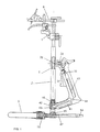
- the positioning device of a proximal end of a tibia (not shown) by compared to a cutting guide 1 has a stem 2 cylindrical oblong.
- a clamp 3 consisting of two forks 3A, 3B intended to grip the malleolus of the tibia articulated to a support 55 and two springs 4A, 4B stressing the two forks so as to tighten the malleolus is mounted on the gallows 2 so that it can slide perpendicular to the plane with the tibia and the gallows (the sagittal plane).
- the hollow oblong stem 2 receives a sliding rod 5 in the upper part of the gallows 2.
- This sliding rod 5 comprises at its lower end of the grooves 6 which will be described later allow positioning with locking the rod 5 relative to the stem 2.
- the upper part of the rod 5 comprises a bore 7 of cross section rectangular which receives a sliding fixing finger 8 in this bore 7 and which can be blocked by a screw 9 in a chosen position.
- the fixing finger 8 has a cylindrical bore 10 receiving a captive nail 11 intended to be plugged into the proximal part tibia, especially in the spine mass of the tibia.
- a another bore 12 is also provided for another spindle or nail.
- Two crossing recesses 13 and 14 are formed in finger 8, in order to lighten the finger and therefore the whole of the device.
- a cutting guide support 15 can slide on the upper part of the rod 5.
- the support 15 includes a bore 16 through which the rod 5 passes and by which the support 15 can slide on this rod 5.
- a screw 17 allows the blocking in the desired position of the support 15 cutting guide on the rod 5.
- the rotation of the support 15 relative to the longitudinal axis of the rod 5 is prevented by providing at the level of the rod 5 where can slide the support 15 a longitudinal groove 25 and a lug in the support 15, which thus prevents a rotation of the support 15 relative to the rod 5.
- the guide section 1 is fixed to the support 15 in a simple manner, by example by the cooperation of a tab 19 with a bore 20 of the section shape cutting guide additional transverse, with separable snap-in, and for this purpose the tongue 19 has a transverse orifice 21 for receiving a hollow rod containing a spring which outwardly requests a retaining ball intended for come and stay in a corresponding notch in the surface of the bore 20 of the cutting guide. So, as well for mounting the cutting guide on the tongue only for disassembly, just move these two manually elements relative to each other by forcing the ball towards inside the orifice 21, this ball emerging from itself either when the two elements are separated, or when the cutting guide is inserted in the tab 19.
- the cutting guide cut has in its upper part a probe assembly removable comprising a body 22, a feeler finger 23 and a column 24.
- Column 24 is inserted in guide 1 of cut in a bore 26 left or 27 right.
- a system ball locking may be provided.
- Body 22 slides on the column 24 by means of a bore 28, while the probing finger 23 slides in a bore 29 transverse to bore 28.
- the sliding of the body 22 on the column 24 can be carried out without mutual rotation, the cross section of the bore 28 being certainly circular, complementary to that of column 24, but the cooperation of finger 23 with the opening 30 prevents rotation of the body 22.
- the sliding of the finger 23 is carried out without possible rotation, the cross section of the bore 29 being square, as that of finger 23.
- the cutting guide 1 conventionally comprises a saw blade counter guiding system or a slot 31 for the passage of a saw blade.
- a handle 32 of revolver This revolver handle 32 includes in its upper part a dog 33 articulated to an axis of rotation 34, the dog 33 cooperating with a spring 35 which urges a first pushing part 36 whose proximal end in spring 35 has rack teeth which can engage in the grooves 6 of the rod 5.
- the handle 32 revolver also includes a trigger 37 articulated by relative to an axis of rotation 38.
- a spring 39 biases the trigger 37 by exerting a return torque in relation to the axis 38.
- the trigger 37 cooperates with a lever 40 disposed at inside the handle 32.
- This lever 40 is bent at comprising two branches, a first branch which cooperates with trigger 37, while its second branch 41 penetrates through its end 42 into a transverse bore 43 of the gallows 2, in its lower part.
- Lever 40 is fixed mounted inside the handle 32, being articulated relative to an axis 44 at the level of the part where join the two arms of lever 40.
- the end 42 of the lever 40 cooperates with a second push piece 45 and a spring return 46, arranged in the bracket 2, being able to slide inside of it.
- the lower end of the second thrust piece 45 includes teeth racks which engage in grooves 47 of one arm support 48 which is oblong, of section transverse square and which slides in a bore 49 of the stem 2 in its lower part.
- Bore 49 is square cross section, complementary to the cross section transverse of the support arm 48.
- the sliding takes place in the medio-lateral plane.
- This support arm 48 comprises at one of its ends a guide plate 50 which can slide in a guide rail 51 formed in the support clamps 3A, 3B.
- the sliding of the guide plate 50 takes place in the plane perpendicular to the stem 2, in the direction perpendicular to the sliding direction of the support arm 48 in the bore 49.
- the outer face of the plate 50 (away from the bracket 2) has a lug 52 which can snap into a row of recesses 53 formed in the wall of the guide rail 51 on which is guided the plate 50.
- the lug 52 can snap into each recess 53 while being pushed there by a spring inside the support arm 48.
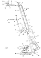
- Adjusting the position of the tibia relative to the cutting guide is carried out as follows: The user enters the positioning system by his handle 32 of revolver and grips the malleoli of the tibia by clamps 3A, 3B which fit tightly with the action of the return springs 4A, 4B. User presses then on the dog 33, with the thumb, the rotation in the clockwise from the dog 33 training the loosening of the spring 35 which brings with it the first pushing part 36, the teeth of part 36 then coming out of their meshing with the grooves 6. With its other hand, the user can then adjust the height of the rod 5 by sliding it in the stem 2.
- the user releases the dog 33 which, by means of the spring 35 repels the push piece 36 engaged by its serrations with the grooves 6 of the rod 5.
- the rod 5 is then blocked and does not can no longer be moved by sliding in the stem 2.
- the user then fixes the upper part of the tibia (mass of thorns) by the nail 11 captive, at the center of the tibia. He supports then on trigger 37.
- This trigger 37 acts on the first branch of lever 40 in link with this trigger 37 and causes the lifting of the second branch 41 of the lever 40, the end 42 of the second branch 41 of the lever 40 then driving towards the top the second push piece 45, the serration of which the lower end comes out of its mesh with the serrations 47 of the support arm 48.
- the support arm 48 can then slide in the bore 49, perpendicular to the bracket 2 and when the angle adjustment in the plane sagittal between the tibia held by its malleoli in the forks 3A, 3B and the stem 2 is carried to the value desired, the user releases trigger 37, which is returned to the free position by the return spring 39.
- the end 42 of the second branch 41 of the lever 40 then lowers and the teeth of the push piece 45 are engaged in the serrations 47 of the support arm 48.
- the posterior slope of the tibia was thus adjusted by compared to the gallows.
- the angle can be chosen between 0 ° and 8 °, by providing a number of teeth 47 sufficient for this adjustment range.
- we perform the angle adjustment varus / valgus in the frontal plane) by sliding the plate 50 in its rail 51, by moving the stem 2 by the handle 32 in the plane perpendicular to FIG. 1 (plane frontal).
- the pin 52 is placed in recess 53 in which it is then, by via a lever 54.
- the number of recesses 53 is provided to allow a setting of for example ⁇ 3 ° of the varus-valgus angle (plane frontal). Height adjustment, posterior slope and varus / valgus having been performed, we then set the probing finger 23 by sliding it over the column 24 to define the exact height of the resection plane. The resection can then be performed. We can then do slide the support 15 of the cutting guide to bring the probing finger 23 in contact with the bone to martialize precisely the resection plane and block the support 15 in position by screw 17.
- the dog and the trigger are both integrated to the handle.
- the user can press the dog with thumb and on the trigger with the index finger easily for all the relative positions of the immobilizing means proximal to the gallows.
- the trigger is independent of the handle and for certain relative positions of the immobilization means proximal to the stem, the user will not have the index long enough to act on the trigger while can simultaneously act on the dog with the thumb.
- means for transmitting the action of the finger on the trigger at the means for adjusting the angle between the gallows and the tibia these means of transmission not part of the gallows.
- these means of transmission consist of at least one lever which is located outside the gallows and in particular is located at inside the pistol grip.
Applications Claiming Priority (2)
| Application Number | Priority Date | Filing Date | Title |
|---|---|---|---|
| FR9904089 | 1999-04-01 | ||
| FR9904089A FR2791549B1 (fr) | 1999-04-01 | 1999-04-01 | Dispositif de positionnement d'une extremite proximale d'un tibia par rapport a un guide de coupe, comportant une poignee de reglage |
Publications (2)
| Publication Number | Publication Date |
|---|---|
| EP1040791A1 true EP1040791A1 (de) | 2000-10-04 |
| EP1040791B1 EP1040791B1 (de) | 2006-05-31 |
Family
ID=9543903
Family Applications (1)
| Application Number | Title | Priority Date | Filing Date |
|---|---|---|---|
| EP00400843A Expired - Lifetime EP1040791B1 (de) | 1999-04-01 | 2000-03-28 | Tibiale Sägeführung mit Regelungshandgriff |
Country Status (6)
| Country | Link |
|---|---|
| US (1) | US6267762B1 (de) |
| EP (1) | EP1040791B1 (de) |
| JP (1) | JP2000300572A (de) |
| DE (1) | DE60028278T2 (de) |
| ES (1) | ES2265324T3 (de) |
| FR (1) | FR2791549B1 (de) |
Cited By (5)
| Publication number | Priority date | Publication date | Assignee | Title |
|---|---|---|---|---|
| WO2009037470A1 (en) * | 2007-09-21 | 2009-03-26 | Depuy International Ltd | Surgical instrument attachment |
| EP2596757A1 (de) | 2011-11-23 | 2013-05-29 | Waldemar Link GmbH & Co. KG | Vorrichtung für die Vorgabe einer Schnittebene für die Knochenresektion |
| US9078674B2 (en) | 2007-09-21 | 2015-07-14 | Depuy (Ireland) | Adjustable surgical instrument |
| CN111887930A (zh) * | 2020-08-27 | 2020-11-06 | 宝鸡市中医医院 | 一种骨科脊柱微创手术钻 |
| CN111938743A (zh) * | 2020-07-17 | 2020-11-17 | 天衍医疗器材有限公司 | 一种胫骨截骨工具系统 |
Families Citing this family (50)
| Publication number | Priority date | Publication date | Assignee | Title |
|---|---|---|---|---|
| US6595997B2 (en) * | 2001-02-28 | 2003-07-22 | Howmedica Osteonics Corp. | Methods used in performing femoral and tibial resection in knee surgery |
| US7909831B2 (en) * | 2001-02-28 | 2011-03-22 | Howmedica Osteonics Corp. | Systems used in performing femoral and tibial resection in knee surgery |
| US6685711B2 (en) * | 2001-02-28 | 2004-02-03 | Howmedica Osteonics Corp. | Apparatus used in performing femoral and tibial resection in knee surgery |
| GB0119540D0 (en) * | 2001-08-10 | 2001-10-03 | Depuy Int Ltd | Tibial resection guide |
| US7618421B2 (en) | 2001-10-10 | 2009-11-17 | Howmedica Osteonics Corp. | Tools for femoral resection in knee surgery |
| CN2519658Y (zh) * | 2001-12-29 | 2002-11-06 | 上海复升医疗器械有限公司 | 安装股骨颈保护装置的器具 |
| AU2003205311A1 (en) * | 2002-01-25 | 2003-09-02 | Depuy Products, Inc. | Extramedullary fluoroscopic alignment guide |
| DE10207035B4 (de) * | 2002-02-20 | 2004-03-25 | Aesculap Ag & Co. Kg | Schablone zur Führung eines chirurgischen Bearbeitungswerkzeuges |
| US7094241B2 (en) | 2002-11-27 | 2006-08-22 | Zimmer Technology, Inc. | Method and apparatus for achieving correct limb alignment in unicondylar knee arthroplasty |
| US20070282347A9 (en) * | 2002-12-20 | 2007-12-06 | Grimm James E | Navigated orthopaedic guide and method |
| US20040172044A1 (en) * | 2002-12-20 | 2004-09-02 | Grimm James E. | Surgical instrument and method of positioning same |
| US7029477B2 (en) * | 2002-12-20 | 2006-04-18 | Zimmer Technology, Inc. | Surgical instrument and positioning method |
| US20040153066A1 (en) * | 2003-02-03 | 2004-08-05 | Coon Thomas M. | Apparatus for knee surgery and method of use |
| GB2398011A (en) * | 2003-02-04 | 2004-08-11 | Robert Michael Wozencroft | Alignment device for use in orthapaedic surgery |
| US7238190B2 (en) * | 2003-03-28 | 2007-07-03 | Concepts In Medicine Iii, Llc | Surgical apparatus to allow replacement of degenerative ankle tissue |
| GB2401550B (en) * | 2003-05-12 | 2005-04-20 | Corin Ltd | Head centering jig for femoral resurfacing |
| US7641661B2 (en) | 2003-12-26 | 2010-01-05 | Zimmer Technology, Inc. | Adjustable resection guide |
| US8043294B2 (en) * | 2004-03-05 | 2011-10-25 | Wright Medical Technology, Inc. | Reference mark adjustment mechanism for a femoral caliper and method of using the same |
| US8114086B2 (en) * | 2004-03-08 | 2012-02-14 | Zimmer Technology, Inc. | Navigated cut guide locator |
| US7993341B2 (en) | 2004-03-08 | 2011-08-09 | Zimmer Technology, Inc. | Navigated orthopaedic guide and method |
| EP1598021B1 (de) * | 2004-05-17 | 2006-06-28 | Zimmer GmbH | Vorrichtung zum Setzen eines Schnittblocks für eine Resektion der Tibia |
| US8167888B2 (en) * | 2004-08-06 | 2012-05-01 | Zimmer Technology, Inc. | Tibial spacer blocks and femoral cutting guide |
| US20060155293A1 (en) * | 2005-01-07 | 2006-07-13 | Zimmer Technology | External rotation cut guide |
| US20060200158A1 (en) * | 2005-01-29 | 2006-09-07 | Farling Toby N | Apparatuses and methods for arthroplastic surgery |
| US8317797B2 (en) | 2005-02-08 | 2012-11-27 | Rasmussen G Lynn | Arthroplasty systems and methods for optimally aligning and tensioning a knee prosthesis |
| US7927336B2 (en) * | 2005-02-08 | 2011-04-19 | Rasmussen G Lynn | Guide assembly for guiding cuts to a femur and tibia during a knee arthroplasty |
| US8303597B2 (en) | 2005-02-08 | 2012-11-06 | Rasmussen G Lynn | Systems and methods for guiding cuts to a femur and tibia during a knee arthroplasty |
| US7618420B2 (en) * | 2005-02-17 | 2009-11-17 | Howmedica Osteonics Corp. | Locking intramedullary jig |
| US7344542B2 (en) * | 2005-02-18 | 2008-03-18 | Howmedica Osteonics Corp. | Pin extraction assembly |
| US20060229543A1 (en) * | 2005-03-13 | 2006-10-12 | Calvo Ignacio J | Wrench for reducing femur midshaft fractures |
| US7601154B2 (en) * | 2005-04-18 | 2009-10-13 | Uni-Knee, Llc | Unicondylar knee instrument system |
| US20070055268A1 (en) * | 2005-08-17 | 2007-03-08 | Aesculap Ag & Co. Kg | Cutting blocks for a surgical procedure and methods for using cutting blocks |
| US20070149977A1 (en) * | 2005-11-28 | 2007-06-28 | Zimmer Technology, Inc. | Surgical component positioner |
| US7520880B2 (en) | 2006-01-09 | 2009-04-21 | Zimmer Technology, Inc. | Adjustable surgical support base with integral hinge |
| US7744600B2 (en) * | 2006-01-10 | 2010-06-29 | Zimmer Technology, Inc. | Bone resection guide and method |
| US7780671B2 (en) | 2006-01-23 | 2010-08-24 | Zimmer Technology, Inc. | Bone resection apparatus and method for knee surgery |
| US20070186738A1 (en) * | 2006-01-31 | 2007-08-16 | Zimmer Technology, Inc. | Tibial cut guide assembly having rotatable cut guide body |
| US8211107B2 (en) * | 2006-05-10 | 2012-07-03 | Concepts In Medicine, Llc | Modular, blade-rod, intramedullary fixation device |
| US20080228191A1 (en) * | 2007-03-13 | 2008-09-18 | Howmedica Osteonics Corp. | Femoral elevator |
| US9138242B2 (en) * | 2007-05-04 | 2015-09-22 | Randall J. Lewis | Femoral hip stem explant system |
| EP2166969B1 (de) * | 2007-07-09 | 2015-04-08 | Orthosoft, Inc. | Universelle positionierungsvorrichtung für orthopädische chirurgie |
| CA2770496C (en) * | 2009-08-06 | 2017-12-05 | Skeletal Dynamics, Llc | Alignable prostheses device, system and method |
| US8551108B2 (en) | 2010-08-31 | 2013-10-08 | Orthosoft Inc. | Tool and method for digital acquisition of a tibial mechanical axis |
| ES2656843T3 (es) * | 2010-08-31 | 2018-02-28 | Orthosoft Inc. | Herramienta para la obtención digital de un eje mecánico tibial |
| DE102018130119A1 (de) | 2018-11-28 | 2020-05-28 | Aesculap Ag | Fixierungssystem und Ausrichtungsvorrichtung |
| JP7207985B2 (ja) * | 2018-12-11 | 2023-01-18 | 京セラ株式会社 | 手術器具 |
| CA3122557A1 (en) * | 2018-12-13 | 2020-06-18 | Paragon 28, Inc. | Joint replacement alignment guides, systems and methods of use and assembly |
| DE102020110346A1 (de) * | 2020-04-15 | 2021-10-21 | Aesculap Ag | Ausrichtungsvorrichtung für eine tibiale Resektionsführung |
| CN111616770B (zh) * | 2020-05-21 | 2021-07-16 | 天衍医疗器材有限公司 | 一种胫骨截骨定位装置 |
| CN112089475B (zh) * | 2020-08-28 | 2021-07-13 | 中南大学湘雅医院 | 股骨头髓外固定式钻孔支架 |
Citations (3)
| Publication number | Priority date | Publication date | Assignee | Title |
|---|---|---|---|---|
| US5451228A (en) * | 1993-09-14 | 1995-09-19 | Zimmer, Inc. | Tibial resector guide |
| FR2720629A1 (fr) * | 1994-06-03 | 1995-12-08 | Landanger Landos | Ancillaire tibial pour la pose d'une platine de coupe sur l'extrémité d'un tibia à sectionner en vue de la mise en place d'une prothèse de genou. |
| US5704941A (en) * | 1995-11-03 | 1998-01-06 | Osteonics Corp. | Tibial preparation apparatus and method |
Family Cites Families (5)
| Publication number | Priority date | Publication date | Assignee | Title |
|---|---|---|---|---|
| US5766173A (en) * | 1993-06-10 | 1998-06-16 | Texas Scottish Rite Hospital For Children | Distractor mechanism for external fixation device |
| US5643272A (en) * | 1994-09-02 | 1997-07-01 | Hudson Surgical Design, Inc. | Method and apparatus for tibial resection |
| US5578039A (en) * | 1995-02-15 | 1996-11-26 | Smith & Nephew Richards Inc. | Tibial resection instrumentation and surgical method |
| US5628750A (en) * | 1995-06-30 | 1997-05-13 | U.S. Medical Products, Inc. | Tibial resection guide alignment apparatus and method |
| US6090114A (en) * | 1997-02-10 | 2000-07-18 | Stryker Howmedica Osteonics Corp. | Tibial plateau resection guide |
-
1999
- 1999-04-01 FR FR9904089A patent/FR2791549B1/fr not_active Expired - Fee Related
-
2000
- 2000-03-28 ES ES00400843T patent/ES2265324T3/es not_active Expired - Lifetime
- 2000-03-28 EP EP00400843A patent/EP1040791B1/de not_active Expired - Lifetime
- 2000-03-28 DE DE60028278T patent/DE60028278T2/de not_active Expired - Lifetime
- 2000-03-28 US US09/535,763 patent/US6267762B1/en not_active Expired - Fee Related
- 2000-03-31 JP JP2000096764A patent/JP2000300572A/ja active Pending
Patent Citations (3)
| Publication number | Priority date | Publication date | Assignee | Title |
|---|---|---|---|---|
| US5451228A (en) * | 1993-09-14 | 1995-09-19 | Zimmer, Inc. | Tibial resector guide |
| FR2720629A1 (fr) * | 1994-06-03 | 1995-12-08 | Landanger Landos | Ancillaire tibial pour la pose d'une platine de coupe sur l'extrémité d'un tibia à sectionner en vue de la mise en place d'une prothèse de genou. |
| US5704941A (en) * | 1995-11-03 | 1998-01-06 | Osteonics Corp. | Tibial preparation apparatus and method |
Cited By (11)
| Publication number | Priority date | Publication date | Assignee | Title |
|---|---|---|---|---|
| WO2009037470A1 (en) * | 2007-09-21 | 2009-03-26 | Depuy International Ltd | Surgical instrument attachment |
| US8496010B2 (en) | 2007-09-21 | 2013-07-30 | Depuy International Limited | Surgical instrument attachment |
| US9078674B2 (en) | 2007-09-21 | 2015-07-14 | Depuy (Ireland) | Adjustable surgical instrument |
| EP2596757A1 (de) | 2011-11-23 | 2013-05-29 | Waldemar Link GmbH & Co. KG | Vorrichtung für die Vorgabe einer Schnittebene für die Knochenresektion |
| WO2013075925A1 (de) | 2011-11-23 | 2013-05-30 | Waldemar Link Gmbh & Co. Kg | Vorrichtung für die vorgabe einer schnittebene für die knochenresektion |
| AU2012342759B2 (en) * | 2011-11-23 | 2014-12-11 | Waldemar Link Gmbh & Co. Kg | Device for defining a cutting plane for bone resection |
| RU2584647C2 (ru) * | 2011-11-23 | 2016-05-20 | Вальдемар Линк Гмбх Унд Ко. Кг | Устройство для установки плоскости разреза для резекции кости |
| US9655632B2 (en) | 2011-11-23 | 2017-05-23 | Waldemar Link Gmbh & Co. Kg | Device for defining a cutting plane for a bone resection |
| CN111938743A (zh) * | 2020-07-17 | 2020-11-17 | 天衍医疗器材有限公司 | 一种胫骨截骨工具系统 |
| CN111887930A (zh) * | 2020-08-27 | 2020-11-06 | 宝鸡市中医医院 | 一种骨科脊柱微创手术钻 |
| CN111887930B (zh) * | 2020-08-27 | 2022-07-05 | 宝鸡市中医医院 | 一种骨科脊柱微创手术钻 |
Also Published As
| Publication number | Publication date |
|---|---|
| ES2265324T3 (es) | 2007-02-16 |
| FR2791549B1 (fr) | 2001-05-25 |
| JP2000300572A (ja) | 2000-10-31 |
| US6267762B1 (en) | 2001-07-31 |
| FR2791549A1 (fr) | 2000-10-06 |
| DE60028278D1 (de) | 2006-07-06 |
| EP1040791B1 (de) | 2006-05-31 |
| DE60028278T2 (de) | 2007-05-03 |
Similar Documents
| Publication | Publication Date | Title |
|---|---|---|
| EP1040791B1 (de) | Tibiale Sägeführung mit Regelungshandgriff | |
| EP0721314B1 (de) | Vorrichtung zur resektion von kondylen eines knies zum einzetzen einer knieprothese | |
| US8080004B2 (en) | Laparoscopic surgical instrument | |
| EP0955930B1 (de) | Regulierbare osteosynthesevorrichtung für die wirbelsäule und positionierungswerkzeug | |
| US6227080B1 (en) | Vice-grip pliers | |
| JP2007532216A (ja) | 骨セパレータ | |
| FR2640870A1 (de) | ||
| FR2943528A1 (fr) | Instrumentation chirurgicale de resection de l'extremite d'un os long | |
| FR2546738A1 (fr) | Dispositif de poignee pour monture de pince coupante interchangeable | |
| WO2012076771A1 (fr) | Dispositif de mise en tension d'une bande souple | |
| FR2508791A1 (fr) | Instrument pour la confection de sutures a deux branches utilise en chirurgie | |
| EP3200710B1 (de) | Zubehör zum spannen eines länglichen elements | |
| EP0401170A1 (de) | Gelenkvorrichtung eines Orthesenstützen-Paares | |
| FR2911264A1 (fr) | Viseur pour chirurgie ligamentaire du genou | |
| CA2471138C (en) | Hacksaw with blade tension adjustment mechanism | |
| FR2716364A1 (fr) | Viseur pour ligamentoplastie antérieure du genou. | |
| FR3026635B1 (fr) | Ancillaire de mise en pre-tension d'un element longiligne pour la fixation d'un implant sur un element osseux | |
| JP7383024B2 (ja) | 固定クランプとアラインメント装置 | |
| EP0793947B1 (de) | Transversale Wirbelsäulenverbindungsvorrichtung | |
| BE1003497A5 (fr) | Outil a main. | |
| JP3225533U (ja) | 高枝切鋏 | |
| EP0385944B1 (de) | Sicherheitsskibindung auf einer Platte | |
| US9108324B1 (en) | Pin cutter | |
| FR2659042A1 (fr) | Dispositif d'assemblage demontable d'un manche sur un outil et plus particulierement mais non exclusivement a un dispositif d'assemblage demontable d'un manche sur une rape a usage chirurgical et manche et outils concus pour etre ainsi assembles. | |
| FR2720629A1 (fr) | Ancillaire tibial pour la pose d'une platine de coupe sur l'extrémité d'un tibia à sectionner en vue de la mise en place d'une prothèse de genou. |
Legal Events
| Date | Code | Title | Description |
|---|---|---|---|
| PUAI | Public reference made under article 153(3) epc to a published international application that has entered the european phase |
Free format text: ORIGINAL CODE: 0009012 |
|
| AK | Designated contracting states |
Kind code of ref document: A1 Designated state(s): DE ES FR GB IT |
|
| AX | Request for extension of the european patent |
Free format text: AL;LT;LV;MK;RO;SI |
|
| 17P | Request for examination filed |
Effective date: 20010214 |
|
| AKX | Designation fees paid |
Free format text: DE ES FR GB IT |
|
| RAP1 | Party data changed (applicant data changed or rights of an application transferred) |
Owner name: AESCULAPSOCIETE PAR ACTIONS SIMPLIFIEE |
|
| 17Q | First examination report despatched |
Effective date: 20050518 |
|
| GRAP | Despatch of communication of intention to grant a patent |
Free format text: ORIGINAL CODE: EPIDOSNIGR1 |
|
| GRAS | Grant fee paid |
Free format text: ORIGINAL CODE: EPIDOSNIGR3 |
|
| GRAA | (expected) grant |
Free format text: ORIGINAL CODE: 0009210 |
|
| AK | Designated contracting states |
Kind code of ref document: B1 Designated state(s): DE ES FR GB IT |
|
| PG25 | Lapsed in a contracting state [announced via postgrant information from national office to epo] |
Ref country code: IT Free format text: LAPSE BECAUSE OF FAILURE TO SUBMIT A TRANSLATION OF THE DESCRIPTION OR TO PAY THE FEE WITHIN THE PRESCRIBED TIME-LIMIT;WARNING: LAPSES OF ITALIAN PATENTS WITH EFFECTIVE DATE BEFORE 2007 MAY HAVE OCCURRED AT ANY TIME BEFORE 2007. THE CORRECT EFFECTIVE DATE MAY BE DIFFERENT FROM THE ONE RECORDED. Effective date: 20060531 |
|
| REG | Reference to a national code |
Ref country code: GB Ref legal event code: FG4D Free format text: NOT ENGLISH |
|
| REF | Corresponds to: |
Ref document number: 60028278 Country of ref document: DE Date of ref document: 20060706 Kind code of ref document: P |
|
| GBT | Gb: translation of ep patent filed (gb section 77(6)(a)/1977) |
Effective date: 20060920 |
|
| REG | Reference to a national code |
Ref country code: ES Ref legal event code: FG2A Ref document number: 2265324 Country of ref document: ES Kind code of ref document: T3 |
|
| PLBE | No opposition filed within time limit |
Free format text: ORIGINAL CODE: 0009261 |
|
| STAA | Information on the status of an ep patent application or granted ep patent |
Free format text: STATUS: NO OPPOSITION FILED WITHIN TIME LIMIT |
|
| 26N | No opposition filed |
Effective date: 20070301 |
|
| PGFP | Annual fee paid to national office [announced via postgrant information from national office to epo] |
Ref country code: FR Payment date: 20120213 Year of fee payment: 13 |
|
| PGFP | Annual fee paid to national office [announced via postgrant information from national office to epo] |
Ref country code: DE Payment date: 20120315 Year of fee payment: 13 |
|
| PGFP | Annual fee paid to national office [announced via postgrant information from national office to epo] |
Ref country code: GB Payment date: 20120209 Year of fee payment: 13 Ref country code: IT Payment date: 20120326 Year of fee payment: 13 |
|
| PGFP | Annual fee paid to national office [announced via postgrant information from national office to epo] |
Ref country code: ES Payment date: 20120323 Year of fee payment: 13 |
|
| GBPC | Gb: european patent ceased through non-payment of renewal fee |
Effective date: 20130328 |
|
| REG | Reference to a national code |
Ref country code: FR Ref legal event code: ST Effective date: 20131129 |
|
| REG | Reference to a national code |
Ref country code: DE Ref legal event code: R119 Ref document number: 60028278 Country of ref document: DE Effective date: 20131001 |
|
| PG25 | Lapsed in a contracting state [announced via postgrant information from national office to epo] |
Ref country code: DE Free format text: LAPSE BECAUSE OF NON-PAYMENT OF DUE FEES Effective date: 20131001 Ref country code: FR Free format text: LAPSE BECAUSE OF NON-PAYMENT OF DUE FEES Effective date: 20130402 Ref country code: GB Free format text: LAPSE BECAUSE OF NON-PAYMENT OF DUE FEES Effective date: 20130328 |
|
| PG25 | Lapsed in a contracting state [announced via postgrant information from national office to epo] |
Ref country code: IT Free format text: LAPSE BECAUSE OF NON-PAYMENT OF DUE FEES Effective date: 20130328 |
|
| REG | Reference to a national code |
Ref country code: ES Ref legal event code: FD2A Effective date: 20140612 |
|
| PG25 | Lapsed in a contracting state [announced via postgrant information from national office to epo] |
Ref country code: ES Free format text: LAPSE BECAUSE OF NON-PAYMENT OF DUE FEES Effective date: 20130329 |