EP1039994B1 - Procede d'obtention d'une lentille ophtalmique comportant une microstructure utilitaire en surface et lentilles ophtalmiques ainsi obtenues - Google Patents
Procede d'obtention d'une lentille ophtalmique comportant une microstructure utilitaire en surface et lentilles ophtalmiques ainsi obtenues Download PDFInfo
- Publication number
- EP1039994B1 EP1039994B1 EP98958281A EP98958281A EP1039994B1 EP 1039994 B1 EP1039994 B1 EP 1039994B1 EP 98958281 A EP98958281 A EP 98958281A EP 98958281 A EP98958281 A EP 98958281A EP 1039994 B1 EP1039994 B1 EP 1039994B1
- Authority
- EP
- European Patent Office
- Prior art keywords
- microstructure
- mould
- insert
- mold
- geometry
- Prior art date
- Legal status (The legal status is an assumption and is not a legal conclusion. Google has not performed a legal analysis and makes no representation as to the accuracy of the status listed.)
- Expired - Lifetime
Links
Images

Classifications
-
- B—PERFORMING OPERATIONS; TRANSPORTING
- B29—WORKING OF PLASTICS; WORKING OF SUBSTANCES IN A PLASTIC STATE IN GENERAL
- B29C—SHAPING OR JOINING OF PLASTICS; SHAPING OF MATERIAL IN A PLASTIC STATE, NOT OTHERWISE PROVIDED FOR; AFTER-TREATMENT OF THE SHAPED PRODUCTS, e.g. REPAIRING
- B29C39/00—Shaping by casting, i.e. introducing the moulding material into a mould or between confining surfaces without significant moulding pressure; Apparatus therefor
- B29C39/02—Shaping by casting, i.e. introducing the moulding material into a mould or between confining surfaces without significant moulding pressure; Apparatus therefor for making articles of definite length, i.e. discrete articles
- B29C39/021—Shaping by casting, i.e. introducing the moulding material into a mould or between confining surfaces without significant moulding pressure; Apparatus therefor for making articles of definite length, i.e. discrete articles by casting in several steps
- B29C39/025—Shaping by casting, i.e. introducing the moulding material into a mould or between confining surfaces without significant moulding pressure; Apparatus therefor for making articles of definite length, i.e. discrete articles by casting in several steps for making multilayered articles
-
- B—PERFORMING OPERATIONS; TRANSPORTING
- B29—WORKING OF PLASTICS; WORKING OF SUBSTANCES IN A PLASTIC STATE IN GENERAL
- B29C—SHAPING OR JOINING OF PLASTICS; SHAPING OF MATERIAL IN A PLASTIC STATE, NOT OTHERWISE PROVIDED FOR; AFTER-TREATMENT OF THE SHAPED PRODUCTS, e.g. REPAIRING
- B29C33/00—Moulds or cores; Details thereof or accessories therefor
- B29C33/42—Moulds or cores; Details thereof or accessories therefor characterised by the shape of the moulding surface, e.g. ribs or grooves
- B29C33/424—Moulding surfaces provided with means for marking or patterning
-
- B—PERFORMING OPERATIONS; TRANSPORTING
- B29—WORKING OF PLASTICS; WORKING OF SUBSTANCES IN A PLASTIC STATE IN GENERAL
- B29C—SHAPING OR JOINING OF PLASTICS; SHAPING OF MATERIAL IN A PLASTIC STATE, NOT OTHERWISE PROVIDED FOR; AFTER-TREATMENT OF THE SHAPED PRODUCTS, e.g. REPAIRING
- B29C45/00—Injection moulding, i.e. forcing the required volume of moulding material through a nozzle into a closed mould; Apparatus therefor
- B29C45/14—Injection moulding, i.e. forcing the required volume of moulding material through a nozzle into a closed mould; Apparatus therefor incorporating preformed parts or layers, e.g. injection moulding around inserts or for coating articles
- B29C45/1418—Injection moulding, i.e. forcing the required volume of moulding material through a nozzle into a closed mould; Apparatus therefor incorporating preformed parts or layers, e.g. injection moulding around inserts or for coating articles the inserts being deformed or preformed, e.g. by the injection pressure
-
- B—PERFORMING OPERATIONS; TRANSPORTING
- B29—WORKING OF PLASTICS; WORKING OF SUBSTANCES IN A PLASTIC STATE IN GENERAL
- B29C—SHAPING OR JOINING OF PLASTICS; SHAPING OF MATERIAL IN A PLASTIC STATE, NOT OTHERWISE PROVIDED FOR; AFTER-TREATMENT OF THE SHAPED PRODUCTS, e.g. REPAIRING
- B29C45/00—Injection moulding, i.e. forcing the required volume of moulding material through a nozzle into a closed mould; Apparatus therefor
- B29C45/17—Component parts, details or accessories; Auxiliary operations
- B29C45/26—Moulds
- B29C45/37—Mould cavity walls, i.e. the inner surface forming the mould cavity, e.g. linings
- B29C45/372—Mould cavity walls, i.e. the inner surface forming the mould cavity, e.g. linings provided with means for marking or patterning, e.g. numbering articles
-
- B—PERFORMING OPERATIONS; TRANSPORTING
- B29—WORKING OF PLASTICS; WORKING OF SUBSTANCES IN A PLASTIC STATE IN GENERAL
- B29C—SHAPING OR JOINING OF PLASTICS; SHAPING OF MATERIAL IN A PLASTIC STATE, NOT OTHERWISE PROVIDED FOR; AFTER-TREATMENT OF THE SHAPED PRODUCTS, e.g. REPAIRING
- B29C69/00—Combinations of shaping techniques not provided for in a single one of main groups B29C39/00 - B29C67/00, e.g. associations of moulding and joining techniques; Apparatus therefore
- B29C69/02—Combinations of shaping techniques not provided for in a single one of main groups B29C39/00 - B29C67/00, e.g. associations of moulding and joining techniques; Apparatus therefore of moulding techniques only
-
- B—PERFORMING OPERATIONS; TRANSPORTING
- B29—WORKING OF PLASTICS; WORKING OF SUBSTANCES IN A PLASTIC STATE IN GENERAL
- B29D—PRODUCING PARTICULAR ARTICLES FROM PLASTICS OR FROM SUBSTANCES IN A PLASTIC STATE
- B29D11/00—Producing optical elements, e.g. lenses or prisms
- B29D11/00009—Production of simple or compound lenses
- B29D11/00038—Production of contact lenses
- B29D11/00125—Auxiliary operations, e.g. removing oxygen from the mould, conveying moulds from a storage to the production line in an inert atmosphere
-
- B—PERFORMING OPERATIONS; TRANSPORTING
- B29—WORKING OF PLASTICS; WORKING OF SUBSTANCES IN A PLASTIC STATE IN GENERAL
- B29D—PRODUCING PARTICULAR ARTICLES FROM PLASTICS OR FROM SUBSTANCES IN A PLASTIC STATE
- B29D11/00—Producing optical elements, e.g. lenses or prisms
- B29D11/00009—Production of simple or compound lenses
- B29D11/00317—Production of lenses with markings or patterns
- B29D11/00326—Production of lenses with markings or patterns having particular surface properties, e.g. a micropattern
-
- B—PERFORMING OPERATIONS; TRANSPORTING
- B29—WORKING OF PLASTICS; WORKING OF SUBSTANCES IN A PLASTIC STATE IN GENERAL
- B29D—PRODUCING PARTICULAR ARTICLES FROM PLASTICS OR FROM SUBSTANCES IN A PLASTIC STATE
- B29D11/00—Producing optical elements, e.g. lenses or prisms
- B29D11/00009—Production of simple or compound lenses
- B29D11/00432—Auxiliary operations, e.g. machines for filling the moulds
-
- B—PERFORMING OPERATIONS; TRANSPORTING
- B29—WORKING OF PLASTICS; WORKING OF SUBSTANCES IN A PLASTIC STATE IN GENERAL
- B29D—PRODUCING PARTICULAR ARTICLES FROM PLASTICS OR FROM SUBSTANCES IN A PLASTIC STATE
- B29D11/00—Producing optical elements, e.g. lenses or prisms
- B29D11/00009—Production of simple or compound lenses
- B29D11/0048—Moulds for lenses
-
- B—PERFORMING OPERATIONS; TRANSPORTING
- B29—WORKING OF PLASTICS; WORKING OF SUBSTANCES IN A PLASTIC STATE IN GENERAL
- B29K—INDEXING SCHEME ASSOCIATED WITH SUBCLASSES B29B, B29C OR B29D, RELATING TO MOULDING MATERIALS OR TO MATERIALS FOR MOULDS, REINFORCEMENTS, FILLERS OR PREFORMED PARTS, e.g. INSERTS
- B29K2995/00—Properties of moulding materials, reinforcements, fillers, preformed parts or moulds
- B29K2995/0018—Properties of moulding materials, reinforcements, fillers, preformed parts or moulds having particular optical properties, e.g. fluorescent or phosphorescent
-
- B—PERFORMING OPERATIONS; TRANSPORTING
- B29—WORKING OF PLASTICS; WORKING OF SUBSTANCES IN A PLASTIC STATE IN GENERAL
- B29L—INDEXING SCHEME ASSOCIATED WITH SUBCLASS B29C, RELATING TO PARTICULAR ARTICLES
- B29L2011/00—Optical elements, e.g. lenses, prisms
- B29L2011/0016—Lenses
Definitions
- the present invention generally relates to a method for obtaining an ophthalmic lens having a utility microstructure on the surface, and more particularly an antireflection microstructure.
- the most commonly used means for imparting anti-reflective properties to ophthalmic lenses, in particular organic glass is to deposit on the lens a layer or a system of anti-reflection layers of mineral materials.
- the use of such an anti-reflection layer made of mineral materials has disadvantages in that it can modify the mechanical properties of the lens obtained, and more particularly can modify the abrasion-resistant properties of the abrasion-resistant hard layers also deposited. on the ophthalmic lens.
- US-A-5,630,902 describes the transfer of a microstructure consisting of diffractive optical elements in a layer of a photopolymerizable material deposited on a plastic substrate by stamping, for example by means of a matrix. in quartz carrying the desired microstructure.
- US-A-4 013 465 discloses a method of producing a surface having a reduced reflection with respect to electromagnetic radiation, which comprises applying to a surface of a substrate a layer of a photosensitive material, to expose this material to a regular pattern of electromagnetic radiation to which it is sensitive and to developing the photosensitive material, so that the topography of the surface of the developed material corresponds to the light patterns, so as to obtain a surface having a reduced reflection of the visible radiation.
- GB-A-2 027 441 discloses a method of manufacturing an article comprising a shaped layer or body of monolithic plastics material consisting of certain cross-linked polymers and having one or more surfaces bearing a replica of a microstructure, which comprises filling a microstructure-carrying master mold with a crosslinkable, oligomeric, crosslinkable, radiation-transferable fluidizable composition having both "hard” and “soft” segments, and exposing the cast composition with actinic radiation to thereby form the article.
- microstructure covers discontinuities, such as projections and indentations, in the surface, the profile of which varies from a mean or central line passing through the microstructure such that the sum of the embraced surfaces by the surface profile above the line is equal to the sum of the areas below the line, the line being substantially parallel to the normal surface (carrying the microstructure) of the article.
- the height of these deviations varies from ⁇ 0.05 ⁇ m to ⁇ 750 ⁇ m over a representative characteristic length of the surface, for example 1 to 30 cm.
- the middle profile or central line can be plane, concave, convex, aspheric or a combination of these forms.
- Articles in which these deviations are of a lower order, that is, from ⁇ 0.005 ⁇ m to 0.1 ⁇ m or, preferably, ⁇ 0.05 ⁇ m, and such deviations are infrequent or of occurrence minimum, that is to say that the surface is free of any significant discontinuity, are those for which the surface carrying the microstructure is a "flat" or "perfectly smooth" surface.
- Such articles are useful, for example, as precision optics or elements with a precision optical interface, such as ophthalmic lenses.
- Articles for which these deviations are of lower order but of frequent occurrence are those, for example, bearing utility discontinuities, as in the case of articles having an antireflection microstructure.
- Articles for which deviations are high order, i.e., from ⁇ 0.1 ⁇ m to ⁇ 750 ⁇ m, to which a microstructure comprising a set of utility discontinuities, which are identical or different, spaced or contiguous, may be assigned, in random or orderly manner, are articles such as retroflecting sheets, linear Fresnel lenses and video disks.
- this document mentions that it may be necessary or desirable to choose the particular oligomeric compositions whose curing shrinkage is low to avoid the appearance of parasitic discontinuities interfering with utility discontinuities.
- US-5,538,674 discloses a method of molding a plastic member carrying a microstructure which comprises providing a master mold having a microstructure; casting a liquid coating on the master mold and solidifying the coating to form a rigid molding tool including the microstructure; placing the molding tool in a molding machine; introducing a plastic element into the molding machine; transferring the microstructure of the molding tool to the plastic element; and removing the molded plastic element from the molding machine.
- U.S. Patent 4,013,465 discloses a method of producing a surface having a reduced reflectance to electromagnetic radiation for a predetermined wavelength band which comprises arranging on the surface of a regular array of protuberances having a height that is not less than one-third of the length of the longest wavelength of the band and a spacing that is less than the length of the shortest wavelength of the band divided by the refractive index of the material of the protuberances.
- the array of protuberances can be made by depositing a layer of a photosensitive material, exposing the material to a regular pattern of electromagnetic radiation and developing the photosensitive material.
- the present invention therefore relates to a method for obtaining an ophthalmic lens, that is to say an article having a corrective geometry of the view, having on the surface a utilitarian microstructure, that is to say having optical properties, in particular anti-reflection properties, the geometry of the utility microstructure being initially determined by an interference method.
- the subject of the present invention is also the lenses thus obtained comprising a surface with a corrective geometry of the sight, provided with a utility microstructure, having anti-reflection properties, whose geometry is initially determined by an interference method.
- This utilitarian microstructure is made in a surface functional layer of the ophthalmic lens which, after curing, constitutes a hard coating having abrasion-resistant properties.
- the corrective geometry surface of the view is a surface with a progressive geometry.
- the curvature of the surface of progressive mold geometry has a radius of curvature measured at any point of the corrective surface between 40 mm and 100 mm.
- the mold used is an integral mold, that is to say that the utility microstructure is formed directly in an inner surface of the mold having the corrective geometry of the required view.
- the mold may be made of plastic, mineral glass or metal, in particular nickel.
- the mold is a composite mold which comprises an insert having a surface in which the utility microstructure is formed, said insert matching the surface of the mold having the corrective geometry of the view, so that the surface of the insert including the utility microstructure also has the corrective geometry of the desired view.
- the insert can be initially shaped to present the correct view of the desired geometry and be attached to the corresponding surface of the mold, for example by means of an adhesive.
- the insert may also initially have a planar shape and then be deformed to conform to the corrective geometry surface of the mold view. In the latter case, the insert can also be attached to the corrective geometry surface of the mold view by means of an adhesive.
- the insert carrying the microstructure is a plastic element intended to be applied to a surface of a mold, this element must have a minimum of elasticity in the plane in order to be properly applied.
- Suitable elements of this type are polyurethane elements having, for example, a Young's modulus measured at 30 ° C. of 1.2 Giga Pascals. In general, the appropriate elements have a Young's modulus of less than 2.5 Giga Pascals.
- the insert may be a layer of material, such as a plastic material formed directly on a surface of a substrate.
- the mold is a composite mold which comprises a planar insert provided on one of its surfaces with the utility microstructure, this planar insert being deformed in the mold to fit the corrective geometry surface of the mold view by application in the mold of a pressure or a hole.
- These optical materials or compositions comprise not only the materials and compositions used to manufacture the ophthalmic lens itself, but also the materials and compositions for the deposition of particular functional layers on an ophthalmic lens, such as materials intended for the formation of ophthalmic lenses. an anti-abrasion layer on an ophthalmic lens.
- the optical material or composition is a thermoplastic material or a liquid composition of thermally curable monomers or by means of actinic radiation.
- Liquid monomer compositions are particularly recommended in the process of the invention.
- alkyl (meth) acrylates in particular (C 1 -C 4 ) alkyl (meth) acrylates such as methyl (meth) acrylate and ethyl (meth) acrylate, allyl derivatives such as allyl carbonates of linear or branched aliphatic or aromatic polyols and thio (meth) acrylic derivatives.
- Particularly preferred monomers in the process of the invention are allyl carbonates of polyols, among which mention may be made of ethylene glycol bis allyl carbonate, diethylene glycol bis 2-methyl carbonate, diethylene glycol bis (allyl carbonate), ethylene glycol bis (2-chloro allyl carbonate), triethylene glycol bis (allyl carbonate), 1,3-propane diol bis (allyl carbonate), propylene glycol bis (2-ethyl allyl carbonate), 1,3-butane diol bis (allyl carbonate), the 1,4-butane diol bis (2-bromo allyl carbonate), dipropylene glycol bis (allyl carbonate), trimethylene glycol bis (2-ethyl allyl carbonate), pentamethylene glycol bis (allyl carbonate), isopropylene bisphenol A bis (allyl carbonate).
- a particularly preferred monomer is diethylene glycol bis (allyl carbonate).
- polyethoxylated aromatic (meth) acrylates such as polyethoxylated bisphenol-A dimethacrylates, in particular those described in the French patent application FR-A- 2,699,541.
- compositions based on polythiols and polyisocyanates in monomeric form, resulting in polythiourethanes as described in particular in US Pat. No. 4,689,387.
- compositions containing one or more di- or polythiol monomers with one or more monomers bearing unsaturated groups reactive with thiol functions such as vinyl, (meth) acrylic and thio (meth) acrylic groups.
- the monomer compositions may comprise mixtures of the above monomers.
- the index of the microstructured layer is preferably equal to or greater than 1.55, more preferably 1.6 or more. It is obvious that this microstructured layer may consist of organic glass or a surface layer such as an anti-abrasion coating deposited on a surface of an organic glass substrate.
- thermoplastic materials useful in the process of the invention mention may be made of thermoplastic prepolymers and polymers such as thermoplastic polycarbonates.
- the Utility microstructure is imparted, not in the ophthalmic lens itself, but in an anti-abrasion functional coating deposited on this lens.
- Any curable monomer compositions suitable for forming an anti-abrasion layer on an ophthalmic lens can be used in the process of the present invention.
- compositions based on silane hydrolyzate in particular epoxysilane hydrolyzate such as those described in French Patent Application No. 93 026 49, and the compositions based on acrylic derivatives.
- optical materials and compositions useful in the process of the present invention may comprise any adjuvants conventionally used in the manufacture of ophthalmic lenses, and in particular initiators and catalysts for thermal and / or photochemical polymerization.
- the geometry of the utility microstructure is initially determined by an interference method, i.e. the utility microstructure is either formed directly on the mold surface by an interference method, or is obtained by transfer from a matrix whose surface comprises a utility microstructure obtained by an interference method.
- the interference method consists in producing an interference fringe pattern by superposing two coherent light waves, for example two laser beams, and irradiating a layer of photosensitive material deposited on a substrate by means of this fringe pattern. interference.
- Two steps of irradiating the photosensitive layer can be provided by rotating the substrate, preferably 90 ° after the first irradiation step, and then developing the layer of photosensitive material.
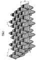
- interference fringe figures having different or identical steps (i) and amplitudes (2A).
- the irradiation steps can also be repeated several times to thereby obtain, after development, a final microstructure consisting of several superimposed microstructures.
- the wavelength of the coherent light beams is between 170 and 510 nm and the pitch of the interference fringe pattern (and consequently of the obtained periodic microstructure) is between 100 and 300 nm.
- the amplitude 2A is generally between 100 and 300 nm.
- plane light waves are used, thereby obtaining a sinusoidal microstructure.
- FIG. 1 shows a system of sinusoidal interference fringes crossed at 90 °.
- the microstructure is slightly deformed with respect to the interference pattern but does not have an abrupt discontinuity.
- the pitch i of the microstructure can vary substantially depending on the situation on the corrective surface.
- This deformation can be eliminated by creating an interference fringe pattern itself modified to take into account the curvature of the surface to be carried by the microstructure.
- the hollows of this microstructure can be filled with a material of refractive index lower than that of the microstructure.
- the index difference of the two materials is preferably greater than or equal to 0.1.
- An anti-fouling material is preferably chosen from a hydrophobic material.
- a suitable antifouling material has the formula: where R is an alkyl radical, for example C 1 -C 6 , and n and n 'are integers which can vary independently from 0 to 6.
- the manufacture of organic glass ophthalmic lenses can be done by molding between two parts 2, 4 of a mold 1, connected by fastening elements 5.
- a material or an optical composition is then introduced into the assembly of the mold through an orifice 6, either by casting or by injection, and is cured or polymerized therein, after disassembling the mold, obtaining an ophthalmic lens.
- at least one of the parts of the mold 2, 4 has an internal surface, for example the surface 3, having a corrective geometry of the view.
- the face internal 3 or 3 'of a portion 2 of the mold is provided with a utility microstructure that is to say having optical properties, preferably anti-reflective properties.
- the mold part 2 whose surface 3 comprises the utility microstructure, is formed directly in the mold part.
- the mold part has the microstructured surface with corrective geometry of metal, for example nickel, or plastic.
- the geometry of this microstructure is initially determined by an interference method, for example using the interference fringe figure shown in FIG.
- a first method for producing an integral mold part provided with a microstructured surface with a corrective geometry consists in producing a metal matrix, for example made of nickel, by electroplating as described above. If the matrix is sufficiently thick it can be used directly as part of the mold.
- a second method for producing an integral mold part, provided with a microstructured surface with a corrective geometry consists in depositing on a surface with a corrective geometry the view of a mineral glass substrate a layer of photosensitive resin, and by the interferential method. previously described, to form there the desired microstructure.
- plasma-isotropic bombardment for example an argon-CHF 3 plasma
- the microstructure is transferred into the glass substrate.
- a third method for producing an integral mold part consists in molding a mold part from a mold, one of whose parts comprises a utility microstructure initially produced by an interference process.
- One method for obtaining a composite mold portion, a portion of which has a microstructured corrective geometry surface is the polymerization duplication.
- a layer of a polymerizable resin is deposited on a corrective geometry surface of a substrate.
- the coated substrate is then brought into close contact with a microstructured surface of a matrix, for example of metal (nickel), for example by vacuum application or by pressing.
- a mold part formed of a substrate having a surface with a corrective geometry is provided. desired utility microstructure.
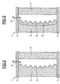
- Figure 3 shows the case where the utility microstructure is carried by an insert 2 ', a surface 3' is provided with the utility microstructure.
- This insert which may be metal, for example nickel, or plastic, can be obtained as indicated above. Since it must be fixed on a surface of the mold part 2 having a corrective geometry of the view, it can be either shaped prior to the desired geometry, or be deformed, for example by stamping, at the time of its installation on the mold part 2 to conform to the geometry of this part. Generally, this insert 2 'is attached to the surface 3 of the mold part 2 by means of an adhesive.
- Obtaining a microstructured ophthalmic lens according to the invention is generally carried out simply by pouring into the mold through the introduction orifice 6 of a liquid composition of optical monomers or by injection of an optical thermoplastic material. After disassembly of the mold, an ophthalmic lens is recovered having a surface carrying a utility microstructure, in particular having anti-reflection properties.
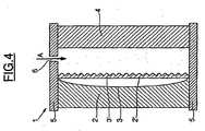
- FIG. 4 shows another embodiment of a mold that can be used in the method of the invention, which is characterized by the fact that it comprises a deformable plane insert 2 'provided on one of its surfaces. a utility microstructure 3 ', preferably having anti-reflective properties.
- This plane insert 2 ' can be deformed during the molding of the ophthalmic lens, by creating a vacuum in the mold 1 on the surface of the the insert opposite the surface 3 'carrying the microstructure, so as to match the geometry of the surface 3 of the mold part 2, generally a corrective geometry of the view.
- this insert 2 ' can be deformed by the pressure exerted by the liquid monomer composition cast in the mold by the insertion orifice 6 or by the optical thermoplastic material injected into the mold through this orifice 6, in this way again, to marry the face with corrective geometry of the view of the part 2 of the mold.
- the deformable insert 2 ' may be an insert of plastic or metallic material, preferably metal, for example nickel.
- An advantage of using such a mold in the process of the invention is that one can form on a flat strip several inserts of similar or different microstructures, cut these inserts and use them in the mold depending on the microstructure desired. In addition, these inserts can be discarded and replaced easily.
- FIG. 5 shows a method for obtaining ophthalmic lenses according to the invention, by transfer molding.
- Figure 5 relates to the technique of coating "in the mold” (In-Mold Coating) well known in the art of manufacturing ophthalmic lenses.
- a layer 8 of an optical material is formed on the mold part 2 having a surface 3 having a corrective geometry of the view and provided with a utility microstructure.
- the microstructure of the mold part 2 is transferred directly into the layer 8.
- a composition or an optical material which is cured or polymerized is introduced either thermally or under the effect of actinic radiation, for example UV radiation.
- an ophthalmic lens is obtained comprising on an optically transparent substrate a microstructured optically transparent layer having the desired corrective geometry.
- mold parts can have any suitable shape, in particular convex, concave or other, depending on the desired corrective geometry.
- the materials constituting the mold parts will be chosen according to the method of polymerization or hardening of the compositions and optical materials used to manufacture the lens or the functional layer on the lens.
- parts of transparent plastic mold will be used in the case of polymerization or curing by means of actinic radiation.
- Example 1 Production of an anti-reflection lens made of diallyl diglycol dicarbonate, resistant to abrasion by an in-mold coating process.
- a nickel insert having a surface having a periodic type microstructure initially resulting from an interference process is bonded to an inner face of a portion of a glass mold.
- the mold obtained is cleaned with acetone and then treated with a solution of fluorohydrocarbide (HCFC) containing 0.26% solid material E-349, a release agent marketed by Chem-Trend Inc.
- HCFC fluorohydrocarbide
- the microstructured face of the mold portion is coated by dipping a layer of a coating composition obtained by alkoxysilane hydrolysis including glycidoxy propyl trimethoxysilane, methyl trimethoxysilane, itaconic acid and colloidal silica.
- the coating composition is precured to a "dust-free" stage, i.e., it is no longer sticky or sticky.
- the portion of the mold coated on its inner side of the microstructure is used to mold the front face of the lens and the conventional mineral glass mold portion (without microstructure) is used to mold the back side of the lens.
- the two mold parts are assembled and held at a distance by a seal and a fastening clip ensures the maintenance of the assembly.
- the mold is then filled with diallyl diglycol dicarbonate (from PPG) containing as catalyst diisopropyl peroxy dicarbonate (also available from PPG).
- the monomeric composition is then thermally cured.
- the mold is disassembled with a suitable tool and a lens is obtained which has abrasion-resistant properties and anti-reflection properties, both superior to an uncoated lens obtained. from a classic mineral glass mold (without microstructure).
- Example 2 Production of an Anti-Reflective Lens, Refractive Index 1.6, Polythiourethane and Resistant to Abrasion by a In-Mold Coating Process.
- a nickel insert provided on one side with a periodic microstructure initially resulting from an interference process is adhered to a surface of a portion of a mineral glass mold.
- the mold is cleaned as in Example 1.
- a coating composition as described in Example 3 of Patent FR-A-93 02649 (glycidoxy propyl trimethoxy silane hydrolyzate, dimethyl diethoxy silane and colloidal silica), is deposited on the microstructured surface by dipping using a coating machine. in the laboratory.
- the coating is precured in the "dust-free" state at a temperature of 80 ° C for 15 minutes.
- the thus coated mold part is used to mold the front face of the lens and the conventional mineral glass mold part (without microstructure) is used to mold the back side of the lens.
- the two mold parts are assembled and held at a distance by a seal and a fastening clip ensures the maintenance of the assembly.
- the mold is then filled with monomer MR6® (marketed by Mitsui-Toatsu Company) containing dibutyltin as a catalyst.
- the monomeric composition is then cured to obtain a 1.6 refractive index polyurethane lens using the following heat-curing cycle in the air: Time (minute) Temperature (° C) O 20 1 32 25 32 33 60 35 80 Removal of the seal. 37 120 39 120 41 75
- the mold is disassembled using a suitable tool to obtain, after post curing at 110 ° C for 3 hours, a lens having scratch-resistant properties in the test of the dyed wool. steel and anti-reflections superior to those of an uncoated lens prepared by a similar method.
- Example 2 is repeated, but using an epoxysilane hydrolyzate coating composition containing colloidal titanium.
- Example 4 Production of a diallyl diglycol dicarbonate plastic mold provided with a microstructure of periodic type.
- Example 2 A mold similar to that of Example 1 is cleaned with acetone. By proceeding as in Example 1, the mold is filled with a composition of diallyl diglycol dicarbonate containing triallyl cyanurate and catalyzed with isopropyl peroxy dicarbonate marketed by PPG Industries. The composition is cured by the following thermal curing cycle: Time (minute) Temperature (° C) 15 46 45 46 30 49 60 49 60 54 45 54 45 58 120 58 45 62.5 45 62.5 60 67.5 45 67.5 60 72 45 72 60 78 60 78
- the mold is disassembled by means of a suitable tool to obtain a substrate provided with a microstructured face.
Landscapes
- Engineering & Computer Science (AREA)
- Mechanical Engineering (AREA)
- Manufacturing & Machinery (AREA)
- Health & Medical Sciences (AREA)
- Ophthalmology & Optometry (AREA)
- Casting Or Compression Moulding Of Plastics Or The Like (AREA)
- Eyeglasses (AREA)
- Moulds For Moulding Plastics Or The Like (AREA)
- Surface Treatment Of Optical Elements (AREA)
Applications Claiming Priority (3)
| Application Number | Priority Date | Filing Date | Title |
|---|---|---|---|
| FR9715712A FR2772302B1 (fr) | 1997-12-11 | 1997-12-11 | Procede d'obtention d'une lentille ophtalmique comportant une microstructure utilitaire en surface et lentilles ophtalmiques ainsi obtenues |
| FR9715712 | 1997-12-11 | ||
| PCT/FR1998/002572 WO1999029494A1 (fr) | 1997-12-11 | 1998-11-30 | Procede d'obtention d'une lentille ophtalmique comportant une microstructure utilitaire en surface et lentilles ophtalmiques ainsi obtenues |
Publications (2)
| Publication Number | Publication Date |
|---|---|
| EP1039994A1 EP1039994A1 (fr) | 2000-10-04 |
| EP1039994B1 true EP1039994B1 (fr) | 2006-01-11 |
Family
ID=9514487
Family Applications (1)
| Application Number | Title | Priority Date | Filing Date |
|---|---|---|---|
| EP98958281A Expired - Lifetime EP1039994B1 (fr) | 1997-12-11 | 1998-11-30 | Procede d'obtention d'une lentille ophtalmique comportant une microstructure utilitaire en surface et lentilles ophtalmiques ainsi obtenues |
Country Status (6)
| Country | Link |
|---|---|
| US (2) | US6491851B1 (enExample) |
| EP (1) | EP1039994B1 (enExample) |
| JP (2) | JP4512267B2 (enExample) |
| DE (1) | DE69833226T2 (enExample) |
| FR (1) | FR2772302B1 (enExample) |
| WO (1) | WO1999029494A1 (enExample) |
Families Citing this family (55)
| Publication number | Priority date | Publication date | Assignee | Title |
|---|---|---|---|---|
| US6825995B2 (en) * | 2000-04-27 | 2004-11-30 | Sony Corporation | Optical device, optical system, method of production of same, and mold for production of same |
| AU2002308631A1 (en) * | 2001-05-07 | 2002-11-18 | Opticast Inc. | Method and apparatus for manufacturing plastic optical lenses and molds |
| KR100439295B1 (ko) * | 2001-05-29 | 2004-07-07 | 유흥상 | 렌즈용 사출금형 및 제작방법 |
| US6562466B2 (en) | 2001-07-02 | 2003-05-13 | Essilor International Compagnie Generale D'optique | Process for transferring a coating onto a surface of a lens blank |
| JP3785093B2 (ja) * | 2001-12-28 | 2006-06-14 | アルプス電気株式会社 | 導光板、その製造方法、照明装置、及び液晶表示装置 |
| US20030164565A1 (en) * | 2002-03-04 | 2003-09-04 | O'brien Keith T. | Method of fabricating an injection mold insert for molding lens molds |
| GB2390327B (en) * | 2002-07-01 | 2005-11-16 | Essilor Int | Process for making a mold piece having a main curved surface bearing a utilitary microstructure |
| JP3994896B2 (ja) * | 2002-09-25 | 2007-10-24 | コニカミノルタホールディングス株式会社 | 映像表示装置 |
| AU2004230413C1 (en) | 2003-04-17 | 2011-01-27 | Essilor International (Compagnie Generale D'optique) | Photocurable adhesive composition and its use in the optical field |
| WO2005035225A1 (en) * | 2003-10-07 | 2005-04-21 | Avery Dennison Corporation | Method of microembossing |
| US20050140033A1 (en) * | 2003-12-31 | 2005-06-30 | Essilor International Compagnie Generale D'optique | Process for making a coated optical article free of visible fining lines |
| EP1723447B1 (en) | 2004-03-02 | 2015-08-26 | ESSILOR INTERNATIONAL (Compagnie Générale d'Optique) | Ophthalmic lens with an optically transparent composite film exhibiting both impact-resistance property and polarizing property, and a process for its manufacture |
| US7439278B2 (en) | 2004-05-04 | 2008-10-21 | Essilor International Compagnie Generale D'optique | Curable adhesive composition and its use in the optical field |
| WO2005123370A1 (en) * | 2004-06-10 | 2005-12-29 | Cabot Safety Intermediate Corporation | Molded-in films for spectacle lenses |
| DE102005013974A1 (de) * | 2005-03-26 | 2006-09-28 | Krauss-Maffei Kunststofftechnik Gmbh | Verfahren und Vorrichtung zur Herstellung mikro- bzw. nanostrukturierter Bauteile |
| US8885251B2 (en) | 2005-04-04 | 2014-11-11 | Essilor International (Compagnie Generale D'optique) | Apparatus for conforming a planar film on an optical lens, method for functionalizing an optical lens by means of said apparatus, the optical lens so-obtained |
| FR2883984B1 (fr) | 2005-04-04 | 2007-06-22 | Essilor Int | Appareil pour conformer un film plan sur une lentille optique, procedes de fonctionnalisation d'une lentille optique au moyen dudit appareil, et lentille ainsi obtenue |
| EP1719612A1 (en) * | 2005-05-03 | 2006-11-08 | Vision Dynamics Holding B.V. | Method of and apparatus for moulding optical components |
| FR2897693B1 (fr) | 2006-02-23 | 2008-11-21 | Essilor Int | Element optique polarisant comprenant un film polariseur et procede de farbrication d'un tel element |
| US20070216064A1 (en) * | 2006-03-16 | 2007-09-20 | Benjamin Logan | Customizable mold |
| SG188917A1 (en) * | 2008-03-18 | 2013-04-30 | Novartis Ag | Coating process for ophthalmic lenses |
| SG172188A1 (en) * | 2008-12-18 | 2011-07-28 | Novartis Ag | Reusable lens molds, methods of use thereof and ophthalmic lenses |
| JP5435824B2 (ja) * | 2009-02-17 | 2014-03-05 | ザ ボード オブ トラスティーズ オブ ザ ユニヴァーシティー オブ イリノイ | マイクロ構造を作製する方法 |
| CN102378926A (zh) * | 2009-03-31 | 2012-03-14 | Hoya株式会社 | 偏光镜片的制造方法和偏光镜片 |
| US20110096403A1 (en) * | 2009-10-22 | 2011-04-28 | Lin Cheng | Anti-glare optical module and method for manufacturing the same |
| US8891171B2 (en) * | 2010-02-01 | 2014-11-18 | Dbm Reflex Enterprises Inc. | High sag thick lens for use in an illumination apparatus |
| WO2011091529A1 (en) * | 2010-02-01 | 2011-08-04 | Dbm Reflex Enterprises Inc. | Thick lens molded with embedded layers of the same resin using a two step injection molding process. |
| US8770749B2 (en) | 2010-04-15 | 2014-07-08 | Oakley, Inc. | Eyewear with chroma enhancement |
| WO2013070417A1 (en) | 2011-10-20 | 2013-05-16 | Oakley, Inc. | Eyewear with chroma enhancement |
| US9242418B2 (en) * | 2011-11-16 | 2016-01-26 | Essilor International | Ophthalmic lens containing a fresnel surface and method for manufacturing same |
| WO2013169987A1 (en) | 2012-05-10 | 2013-11-14 | Oakley, Inc. | Eyewear with laminated functional layers |
| DE102012020363B4 (de) * | 2012-10-17 | 2022-07-07 | Rodenstock Gmbh | Erzeugung mikrostrukturierter Gießformen |
| DE102012025740B3 (de) | 2012-10-17 | 2022-07-21 | Rodenstock Gmbh | Erzeugung mikrostrukturierter Stempel |
| DE102012023025A1 (de) * | 2012-11-23 | 2014-05-28 | Rodenstock Gmbh | Erzeugung mikrostrukturierter Brillengläser mittels Transferschicht |
| US10137661B2 (en) | 2013-04-05 | 2018-11-27 | Mitsubishi Chemical Corporation | Microrelief structural body, decorative sheet, decorative resin molded body, method for producing microrelief structural body, and method for producing decorative resin molded body |
| WO2015049406A1 (es) * | 2013-10-02 | 2015-04-09 | Sgenia Soluciones | Lente antirreflectante para gafas y procedimiento de fabricación de dicha lente |
| US9575335B1 (en) | 2014-01-10 | 2017-02-21 | Oakley, Inc. | Eyewear with chroma enhancement for specific activities |
| US10871661B2 (en) | 2014-05-23 | 2020-12-22 | Oakley, Inc. | Eyewear and lenses with multiple molded lens components |
| EP3218763A4 (en) | 2014-11-13 | 2018-06-13 | Oakley, Inc. | Variable light attenuation eyewear with color enhancement |
| DE102014119470A1 (de) | 2014-12-22 | 2016-06-23 | Leibniz-Institut Für Neue Materialien Gemeinnützige Gmbh | Strukturierte Oberfläche mit stufenweise schaltbarer Adhäsion |
| DE102015103965A1 (de) * | 2015-03-17 | 2016-09-22 | Leibniz-Institut Für Neue Materialien Gemeinnützige Gmbh | Komposit-Pillarstrukturen |
| JP5884249B1 (ja) * | 2015-03-27 | 2016-03-15 | ナルックス株式会社 | 射出圧縮成形装置及び射出圧縮成形方法 |
| US12124116B2 (en) | 2017-10-20 | 2024-10-22 | Luxottica S.R.L. | Eyewear with variable transmission lens |
| JP7216667B2 (ja) * | 2017-12-19 | 2023-02-01 | ホヤ レンズ タイランド リミテッド | 眼鏡レンズ成形型の製造方法及び眼鏡レンズの製造方法 |
| US11112622B2 (en) | 2018-02-01 | 2021-09-07 | Luxottica S.R.L. | Eyewear and lenses with multiple molded lens components |
| DE102018119314A1 (de) * | 2018-08-08 | 2020-02-13 | Osram Opto Semiconductors Gmbh | Verfahren zur Herstellung von Auskoppelelementen, Auskoppelelement und lichtemittierendes Halbleiterbauteil |
| PL3896499T3 (pl) * | 2020-04-17 | 2024-04-22 | Essilor International | Ulepszony sposób formowania wyrobu optycznego zawierającego mikrosoczewki |
| DE102020134055B9 (de) | 2020-12-17 | 2025-07-17 | Sioptica Gmbh | Abformverfahren zur Herstellung eines Licht-leitenden 3D-Formkörpers sowie Abformwerkzeug zur Verwendung in dem Verfahren |
| EP4052883A1 (fr) * | 2021-03-03 | 2022-09-07 | Rolex Sa | Procédé de fabrication d'un composant horloger |
| DE102021110777A1 (de) | 2021-04-27 | 2022-10-27 | Carl Zeiss Meditec Ag | Verfahren und Herstellungsvorrichtung zum Herstellen einer ophthalmischen Linse |
| EP4094932B1 (en) | 2021-05-26 | 2024-09-04 | Essilor International | Composite mold for manufacturing a microstructured thermoset article, manufacturing method and method for obtaining the mold |
| EP4119321A1 (en) * | 2021-07-13 | 2023-01-18 | Essilor International | Method for fabricating microstructured inserts for injection molding |
| EP4373658A1 (en) * | 2021-07-19 | 2024-05-29 | Essilor International | Mold for manufacturing a thermoset optical article, method for manufacturing the mold and method for manufacturing the thermoset optical article |
| WO2024103259A1 (en) | 2022-11-15 | 2024-05-23 | Carl Zeiss Vision Technical Services (Guangzhou) Ltd. | A mold appartus for manufacturing a spectacle lens and relevant methods |
| WO2024133820A1 (en) | 2022-12-21 | 2024-06-27 | Essilor International | Method of curing a polythiourethane based substrate coupled to a microstructured wafer |
Family Cites Families (25)
| Publication number | Priority date | Publication date | Assignee | Title |
|---|---|---|---|---|
| US2230009A (en) * | 1938-10-27 | 1941-01-28 | Gaff Mex | Antiglare glasses |
| GB1462618A (en) * | 1973-05-10 | 1977-01-26 | Secretary Industry Brit | Reducing the reflectance of surfaces to radiation |
| DE2839249A1 (de) * | 1977-09-12 | 1979-03-22 | Toray Industries | Verfahren zur herstellung einer weichen kontaktlinse und ausgangsloesung zur durchfuehrung des verfahrens |
| US4582885A (en) * | 1978-07-20 | 1986-04-15 | Minnesota Mining And Manufacturing Company | Shaped plastic articles having replicated microstructure surfaces |
| US4576850A (en) * | 1978-07-20 | 1986-03-18 | Minnesota Mining And Manufacturing Company | Shaped plastic articles having replicated microstructure surfaces |
| WO1981002941A1 (en) * | 1980-04-11 | 1981-10-15 | R Lawson | An improved musical expression pedal |
| JPS5772822A (en) * | 1980-10-27 | 1982-05-07 | Hitachi Ltd | Production of plastic lens |
| DE3117474A1 (de) * | 1981-05-02 | 1982-11-18 | Fa. Carl Zeiss, 7920 Heidenheim | Verfahren und vorrichtung zum herstellen von formteilen mit asphaerischen oberflaechen |
| JPS57205120A (en) * | 1981-06-12 | 1982-12-16 | Ricoh Co Ltd | Molding of aspherical lens |
| JPH0243590A (ja) * | 1988-08-03 | 1990-02-14 | Sharp Corp | ブレーズホログラムの製造方法 |
| US5071597A (en) * | 1989-06-02 | 1991-12-10 | American Bank Note Holographics, Inc. | Plastic molding of articles including a hologram or other microstructure |
| FR2663431B1 (fr) * | 1990-06-14 | 1992-09-11 | Commissariat Energie Atomique | Magnetometre a resonance magnetique et a enroulements d'excitation multiplexes. |
| US5229797A (en) * | 1990-08-08 | 1993-07-20 | Minnesota Mining And Manufacturing Company | Multifocal diffractive ophthalmic lenses |
| JPH0497812A (ja) * | 1990-08-14 | 1992-03-30 | Toshiba Corp | プラスチック製光学部品成形用金型 |
| AU1343092A (en) * | 1992-01-09 | 1993-08-03 | Scott R. Fohrman | Reproduction of holograms |
| FR2699541B1 (fr) * | 1992-12-22 | 1995-04-28 | Essilor Int | Compositions polymères à faible indice de jaune, compositions polymérisables et lentilles les mettant en Óoeuvre. |
| FR2702486B1 (fr) * | 1993-03-08 | 1995-04-21 | Essilor Int | Compositions de revêtement antiabrasion à base d'hydrolysats de silanes et de composés de l'aluminium, et articles revêtus correspondants résistants à l'abrasion et aux chocs. |
| JPH0749471A (ja) * | 1993-08-06 | 1995-02-21 | Kuraray Co Ltd | 眼 鏡 |
| US5538674A (en) * | 1993-11-19 | 1996-07-23 | Donnelly Corporation | Method for reproducing holograms, kinoforms, diffractive optical elements and microstructures |
| JP3323614B2 (ja) * | 1993-12-27 | 2002-09-09 | 株式会社日立製作所 | 透明部材とその製造方法 |
| US5630902A (en) * | 1994-12-30 | 1997-05-20 | Honeywell Inc. | Apparatus for use in high fidelty replication of diffractive optical elements |
| US5728324A (en) * | 1995-01-31 | 1998-03-17 | Digital Optics Corporation | Molding diffractive optical elements |
| JPH08252829A (ja) * | 1995-03-16 | 1996-10-01 | Seiko Epson Corp | プラスチックレンズの製造方法および積層体 |
| FR2734827B1 (fr) * | 1995-05-31 | 1997-07-11 | Essilor Int | Compositions polymerisables a base de monomeres thio (meth)acrylates, polymeres a faible indice de jaune obtenus a partir de telles compositions et lentilles ophtalmiques correspondantes |
| US5938989A (en) * | 1997-01-24 | 1999-08-17 | Mems Optical, Inc. | Diffractive optical elements |
-
1997
- 1997-12-11 FR FR9715712A patent/FR2772302B1/fr not_active Expired - Fee Related
-
1998
- 1998-11-30 DE DE69833226T patent/DE69833226T2/de not_active Expired - Lifetime
- 1998-11-30 EP EP98958281A patent/EP1039994B1/fr not_active Expired - Lifetime
- 1998-11-30 JP JP2000524124A patent/JP4512267B2/ja not_active Expired - Fee Related
- 1998-11-30 WO PCT/FR1998/002572 patent/WO1999029494A1/fr not_active Ceased
-
2000
- 2000-06-09 US US09/590,800 patent/US6491851B1/en not_active Expired - Fee Related
-
2002
- 2002-06-24 US US10/179,922 patent/US20030075814A1/en not_active Abandoned
-
2009
- 2009-09-17 JP JP2009215789A patent/JP2010033064A/ja active Pending
Also Published As
| Publication number | Publication date |
|---|---|
| US6491851B1 (en) | 2002-12-10 |
| EP1039994A1 (fr) | 2000-10-04 |
| FR2772302B1 (fr) | 2000-01-21 |
| US20030075814A1 (en) | 2003-04-24 |
| JP2001525269A (ja) | 2001-12-11 |
| DE69833226T2 (de) | 2006-09-14 |
| DE69833226D1 (de) | 2006-04-06 |
| WO1999029494A1 (fr) | 1999-06-17 |
| FR2772302A1 (fr) | 1999-06-18 |
| JP4512267B2 (ja) | 2010-07-28 |
| JP2010033064A (ja) | 2010-02-12 |
Similar Documents
| Publication | Publication Date | Title |
|---|---|---|
| EP1039994B1 (fr) | Procede d'obtention d'une lentille ophtalmique comportant une microstructure utilitaire en surface et lentilles ophtalmiques ainsi obtenues | |
| CN112888973B (zh) | 包含光学元件的改进的光学制品及其制造方法 | |
| EP1177465B1 (fr) | Lentille ophtalmique composite et procede d'obtention d'une telle lentille | |
| US7520972B2 (en) | Process for making a mold piece having a main curved surface bearing a utilitary microstructure | |
| EP2024765A1 (fr) | Pastille de modification d'une puissance d'un composant optique | |
| JP2016500842A (ja) | 保護された微細構造を有する眼鏡レンズの作製 | |
| CA2725056A1 (en) | Process for applying a coating onto a fresnel lens forming surface | |
| CN115398279A (zh) | 用于形成包括微透镜的光学制品的改进方法 | |
| EP3720692B1 (en) | Method of additively manufacturing an ophthalmic lens and ophthalmic lens | |
| JP4261344B2 (ja) | インサートを有するレンズを型で作る方法 | |
| JP4030601B2 (ja) | 眼鏡用樹脂レンズの成形用スタンパ | |
| JP2003344814A (ja) | 二重焦点レンズ |
Legal Events
| Date | Code | Title | Description |
|---|---|---|---|
| PUAI | Public reference made under article 153(3) epc to a published international application that has entered the european phase |
Free format text: ORIGINAL CODE: 0009012 |
|
| 17P | Request for examination filed |
Effective date: 20000711 |
|
| AK | Designated contracting states |
Kind code of ref document: A1 Designated state(s): DE FR GB IT |
|
| 17Q | First examination report despatched |
Effective date: 20010719 |
|
| GRAP | Despatch of communication of intention to grant a patent |
Free format text: ORIGINAL CODE: EPIDOSNIGR1 |
|
| GRAS | Grant fee paid |
Free format text: ORIGINAL CODE: EPIDOSNIGR3 |
|
| GRAA | (expected) grant |
Free format text: ORIGINAL CODE: 0009210 |
|
| AK | Designated contracting states |
Kind code of ref document: B1 Designated state(s): DE FR GB IT |
|
| PG25 | Lapsed in a contracting state [announced via postgrant information from national office to epo] |
Ref country code: IT Free format text: LAPSE BECAUSE OF FAILURE TO SUBMIT A TRANSLATION OF THE DESCRIPTION OR TO PAY THE FEE WITHIN THE PRESCRIBED TIME-LIMIT;WARNING: LAPSES OF ITALIAN PATENTS WITH EFFECTIVE DATE BEFORE 2007 MAY HAVE OCCURRED AT ANY TIME BEFORE 2007. THE CORRECT EFFECTIVE DATE MAY BE DIFFERENT FROM THE ONE RECORDED. Effective date: 20060111 |
|
| REF | Corresponds to: |
Ref document number: 69833226 Country of ref document: DE Date of ref document: 20060406 Kind code of ref document: P |
|
| GBT | Gb: translation of ep patent filed (gb section 77(6)(a)/1977) |
Effective date: 20060502 |
|
| PLBE | No opposition filed within time limit |
Free format text: ORIGINAL CODE: 0009261 |
|
| STAA | Information on the status of an ep patent application or granted ep patent |
Free format text: STATUS: NO OPPOSITION FILED WITHIN TIME LIMIT |
|
| 26N | No opposition filed |
Effective date: 20061012 |
|
| PGFP | Annual fee paid to national office [announced via postgrant information from national office to epo] |
Ref country code: DE Payment date: 20131127 Year of fee payment: 16 Ref country code: GB Payment date: 20131127 Year of fee payment: 16 Ref country code: FR Payment date: 20131118 Year of fee payment: 16 |
|
| REG | Reference to a national code |
Ref country code: DE Ref legal event code: R119 Ref document number: 69833226 Country of ref document: DE |
|
| GBPC | Gb: european patent ceased through non-payment of renewal fee |
Effective date: 20141130 |
|
| REG | Reference to a national code |
Ref country code: FR Ref legal event code: ST Effective date: 20150731 |
|
| PG25 | Lapsed in a contracting state [announced via postgrant information from national office to epo] |
Ref country code: DE Free format text: LAPSE BECAUSE OF NON-PAYMENT OF DUE FEES Effective date: 20150602 Ref country code: GB Free format text: LAPSE BECAUSE OF NON-PAYMENT OF DUE FEES Effective date: 20141130 |
|
| PG25 | Lapsed in a contracting state [announced via postgrant information from national office to epo] |
Ref country code: FR Free format text: LAPSE BECAUSE OF NON-PAYMENT OF DUE FEES Effective date: 20141201 |
|
| P01 | Opt-out of the competence of the unified patent court (upc) registered |
Effective date: 20230525 |