EP1039994B1 - Method for obtaining an ophthalmic lens comprising a surface utility microstructure and resulting ophthalmic lenses - Google Patents
Method for obtaining an ophthalmic lens comprising a surface utility microstructure and resulting ophthalmic lenses Download PDFInfo
- Publication number
- EP1039994B1 EP1039994B1 EP98958281A EP98958281A EP1039994B1 EP 1039994 B1 EP1039994 B1 EP 1039994B1 EP 98958281 A EP98958281 A EP 98958281A EP 98958281 A EP98958281 A EP 98958281A EP 1039994 B1 EP1039994 B1 EP 1039994B1
- Authority
- EP
- European Patent Office
- Prior art keywords
- microstructure
- mould
- insert
- mold
- geometry
- Prior art date
- Legal status (The legal status is an assumption and is not a legal conclusion. Google has not performed a legal analysis and makes no representation as to the accuracy of the status listed.)
- Expired - Lifetime
Links
Images

Classifications
-
- B—PERFORMING OPERATIONS; TRANSPORTING
- B29—WORKING OF PLASTICS; WORKING OF SUBSTANCES IN A PLASTIC STATE IN GENERAL
- B29C—SHAPING OR JOINING OF PLASTICS; SHAPING OF MATERIAL IN A PLASTIC STATE, NOT OTHERWISE PROVIDED FOR; AFTER-TREATMENT OF THE SHAPED PRODUCTS, e.g. REPAIRING
- B29C39/00—Shaping by casting, i.e. introducing the moulding material into a mould or between confining surfaces without significant moulding pressure; Apparatus therefor
- B29C39/02—Shaping by casting, i.e. introducing the moulding material into a mould or between confining surfaces without significant moulding pressure; Apparatus therefor for making articles of definite length, i.e. discrete articles
- B29C39/021—Shaping by casting, i.e. introducing the moulding material into a mould or between confining surfaces without significant moulding pressure; Apparatus therefor for making articles of definite length, i.e. discrete articles by casting in several steps
- B29C39/025—Shaping by casting, i.e. introducing the moulding material into a mould or between confining surfaces without significant moulding pressure; Apparatus therefor for making articles of definite length, i.e. discrete articles by casting in several steps for making multilayered articles
-
- B—PERFORMING OPERATIONS; TRANSPORTING
- B29—WORKING OF PLASTICS; WORKING OF SUBSTANCES IN A PLASTIC STATE IN GENERAL
- B29C—SHAPING OR JOINING OF PLASTICS; SHAPING OF MATERIAL IN A PLASTIC STATE, NOT OTHERWISE PROVIDED FOR; AFTER-TREATMENT OF THE SHAPED PRODUCTS, e.g. REPAIRING
- B29C33/00—Moulds or cores; Details thereof or accessories therefor
- B29C33/42—Moulds or cores; Details thereof or accessories therefor characterised by the shape of the moulding surface, e.g. ribs or grooves
- B29C33/424—Moulding surfaces provided with means for marking or patterning
-
- B—PERFORMING OPERATIONS; TRANSPORTING
- B29—WORKING OF PLASTICS; WORKING OF SUBSTANCES IN A PLASTIC STATE IN GENERAL
- B29C—SHAPING OR JOINING OF PLASTICS; SHAPING OF MATERIAL IN A PLASTIC STATE, NOT OTHERWISE PROVIDED FOR; AFTER-TREATMENT OF THE SHAPED PRODUCTS, e.g. REPAIRING
- B29C45/00—Injection moulding, i.e. forcing the required volume of moulding material through a nozzle into a closed mould; Apparatus therefor
- B29C45/14—Injection moulding, i.e. forcing the required volume of moulding material through a nozzle into a closed mould; Apparatus therefor incorporating preformed parts or layers, e.g. injection moulding around inserts or for coating articles
- B29C45/1418—Injection moulding, i.e. forcing the required volume of moulding material through a nozzle into a closed mould; Apparatus therefor incorporating preformed parts or layers, e.g. injection moulding around inserts or for coating articles the inserts being deformed or preformed, e.g. by the injection pressure
-
- B—PERFORMING OPERATIONS; TRANSPORTING
- B29—WORKING OF PLASTICS; WORKING OF SUBSTANCES IN A PLASTIC STATE IN GENERAL
- B29C—SHAPING OR JOINING OF PLASTICS; SHAPING OF MATERIAL IN A PLASTIC STATE, NOT OTHERWISE PROVIDED FOR; AFTER-TREATMENT OF THE SHAPED PRODUCTS, e.g. REPAIRING
- B29C45/00—Injection moulding, i.e. forcing the required volume of moulding material through a nozzle into a closed mould; Apparatus therefor
- B29C45/17—Component parts, details or accessories; Auxiliary operations
- B29C45/26—Moulds
- B29C45/37—Mould cavity walls, i.e. the inner surface forming the mould cavity, e.g. linings
- B29C45/372—Mould cavity walls, i.e. the inner surface forming the mould cavity, e.g. linings provided with means for marking or patterning, e.g. numbering articles
-
- B—PERFORMING OPERATIONS; TRANSPORTING
- B29—WORKING OF PLASTICS; WORKING OF SUBSTANCES IN A PLASTIC STATE IN GENERAL
- B29C—SHAPING OR JOINING OF PLASTICS; SHAPING OF MATERIAL IN A PLASTIC STATE, NOT OTHERWISE PROVIDED FOR; AFTER-TREATMENT OF THE SHAPED PRODUCTS, e.g. REPAIRING
- B29C69/00—Combinations of shaping techniques not provided for in a single one of main groups B29C39/00 - B29C67/00, e.g. associations of moulding and joining techniques; Apparatus therefore
- B29C69/02—Combinations of shaping techniques not provided for in a single one of main groups B29C39/00 - B29C67/00, e.g. associations of moulding and joining techniques; Apparatus therefore of moulding techniques only
-
- B—PERFORMING OPERATIONS; TRANSPORTING
- B29—WORKING OF PLASTICS; WORKING OF SUBSTANCES IN A PLASTIC STATE IN GENERAL
- B29D—PRODUCING PARTICULAR ARTICLES FROM PLASTICS OR FROM SUBSTANCES IN A PLASTIC STATE
- B29D11/00—Producing optical elements, e.g. lenses or prisms
- B29D11/00009—Production of simple or compound lenses
- B29D11/00038—Production of contact lenses
- B29D11/00125—Auxiliary operations, e.g. removing oxygen from the mould, conveying moulds from a storage to the production line in an inert atmosphere
-
- B—PERFORMING OPERATIONS; TRANSPORTING
- B29—WORKING OF PLASTICS; WORKING OF SUBSTANCES IN A PLASTIC STATE IN GENERAL
- B29D—PRODUCING PARTICULAR ARTICLES FROM PLASTICS OR FROM SUBSTANCES IN A PLASTIC STATE
- B29D11/00—Producing optical elements, e.g. lenses or prisms
- B29D11/00009—Production of simple or compound lenses
- B29D11/00317—Production of lenses with markings or patterns
- B29D11/00326—Production of lenses with markings or patterns having particular surface properties, e.g. a micropattern
-
- B—PERFORMING OPERATIONS; TRANSPORTING
- B29—WORKING OF PLASTICS; WORKING OF SUBSTANCES IN A PLASTIC STATE IN GENERAL
- B29D—PRODUCING PARTICULAR ARTICLES FROM PLASTICS OR FROM SUBSTANCES IN A PLASTIC STATE
- B29D11/00—Producing optical elements, e.g. lenses or prisms
- B29D11/00009—Production of simple or compound lenses
- B29D11/00432—Auxiliary operations, e.g. machines for filling the moulds
-
- B—PERFORMING OPERATIONS; TRANSPORTING
- B29—WORKING OF PLASTICS; WORKING OF SUBSTANCES IN A PLASTIC STATE IN GENERAL
- B29D—PRODUCING PARTICULAR ARTICLES FROM PLASTICS OR FROM SUBSTANCES IN A PLASTIC STATE
- B29D11/00—Producing optical elements, e.g. lenses or prisms
- B29D11/00009—Production of simple or compound lenses
- B29D11/0048—Moulds for lenses
-
- B—PERFORMING OPERATIONS; TRANSPORTING
- B29—WORKING OF PLASTICS; WORKING OF SUBSTANCES IN A PLASTIC STATE IN GENERAL
- B29K—INDEXING SCHEME ASSOCIATED WITH SUBCLASSES B29B, B29C OR B29D, RELATING TO MOULDING MATERIALS OR TO MATERIALS FOR MOULDS, REINFORCEMENTS, FILLERS OR PREFORMED PARTS, e.g. INSERTS
- B29K2995/00—Properties of moulding materials, reinforcements, fillers, preformed parts or moulds
- B29K2995/0018—Properties of moulding materials, reinforcements, fillers, preformed parts or moulds having particular optical properties, e.g. fluorescent or phosphorescent
-
- B—PERFORMING OPERATIONS; TRANSPORTING
- B29—WORKING OF PLASTICS; WORKING OF SUBSTANCES IN A PLASTIC STATE IN GENERAL
- B29L—INDEXING SCHEME ASSOCIATED WITH SUBCLASS B29C, RELATING TO PARTICULAR ARTICLES
- B29L2011/00—Optical elements, e.g. lenses, prisms
- B29L2011/0016—Lenses
Definitions
- the present invention generally relates to a method for obtaining an ophthalmic lens having a utility microstructure on the surface, and more particularly an antireflection microstructure.
- the most commonly used means for imparting anti-reflective properties to ophthalmic lenses, in particular organic glass is to deposit on the lens a layer or a system of anti-reflection layers of mineral materials.
- the use of such an anti-reflection layer made of mineral materials has disadvantages in that it can modify the mechanical properties of the lens obtained, and more particularly can modify the abrasion-resistant properties of the abrasion-resistant hard layers also deposited. on the ophthalmic lens.
- US-A-5,630,902 describes the transfer of a microstructure consisting of diffractive optical elements in a layer of a photopolymerizable material deposited on a plastic substrate by stamping, for example by means of a matrix. in quartz carrying the desired microstructure.
- US-A-4 013 465 discloses a method of producing a surface having a reduced reflection with respect to electromagnetic radiation, which comprises applying to a surface of a substrate a layer of a photosensitive material, to expose this material to a regular pattern of electromagnetic radiation to which it is sensitive and to developing the photosensitive material, so that the topography of the surface of the developed material corresponds to the light patterns, so as to obtain a surface having a reduced reflection of the visible radiation.
- GB-A-2 027 441 discloses a method of manufacturing an article comprising a shaped layer or body of monolithic plastics material consisting of certain cross-linked polymers and having one or more surfaces bearing a replica of a microstructure, which comprises filling a microstructure-carrying master mold with a crosslinkable, oligomeric, crosslinkable, radiation-transferable fluidizable composition having both "hard” and “soft” segments, and exposing the cast composition with actinic radiation to thereby form the article.
- microstructure covers discontinuities, such as projections and indentations, in the surface, the profile of which varies from a mean or central line passing through the microstructure such that the sum of the embraced surfaces by the surface profile above the line is equal to the sum of the areas below the line, the line being substantially parallel to the normal surface (carrying the microstructure) of the article.
- the height of these deviations varies from ⁇ 0.05 ⁇ m to ⁇ 750 ⁇ m over a representative characteristic length of the surface, for example 1 to 30 cm.
- the middle profile or central line can be plane, concave, convex, aspheric or a combination of these forms.
- Articles in which these deviations are of a lower order, that is, from ⁇ 0.005 ⁇ m to 0.1 ⁇ m or, preferably, ⁇ 0.05 ⁇ m, and such deviations are infrequent or of occurrence minimum, that is to say that the surface is free of any significant discontinuity, are those for which the surface carrying the microstructure is a "flat" or "perfectly smooth" surface.
- Such articles are useful, for example, as precision optics or elements with a precision optical interface, such as ophthalmic lenses.
- Articles for which these deviations are of lower order but of frequent occurrence are those, for example, bearing utility discontinuities, as in the case of articles having an antireflection microstructure.
- Articles for which deviations are high order, i.e., from ⁇ 0.1 ⁇ m to ⁇ 750 ⁇ m, to which a microstructure comprising a set of utility discontinuities, which are identical or different, spaced or contiguous, may be assigned, in random or orderly manner, are articles such as retroflecting sheets, linear Fresnel lenses and video disks.
- this document mentions that it may be necessary or desirable to choose the particular oligomeric compositions whose curing shrinkage is low to avoid the appearance of parasitic discontinuities interfering with utility discontinuities.
- US-5,538,674 discloses a method of molding a plastic member carrying a microstructure which comprises providing a master mold having a microstructure; casting a liquid coating on the master mold and solidifying the coating to form a rigid molding tool including the microstructure; placing the molding tool in a molding machine; introducing a plastic element into the molding machine; transferring the microstructure of the molding tool to the plastic element; and removing the molded plastic element from the molding machine.
- U.S. Patent 4,013,465 discloses a method of producing a surface having a reduced reflectance to electromagnetic radiation for a predetermined wavelength band which comprises arranging on the surface of a regular array of protuberances having a height that is not less than one-third of the length of the longest wavelength of the band and a spacing that is less than the length of the shortest wavelength of the band divided by the refractive index of the material of the protuberances.
- the array of protuberances can be made by depositing a layer of a photosensitive material, exposing the material to a regular pattern of electromagnetic radiation and developing the photosensitive material.
- the present invention therefore relates to a method for obtaining an ophthalmic lens, that is to say an article having a corrective geometry of the view, having on the surface a utilitarian microstructure, that is to say having optical properties, in particular anti-reflection properties, the geometry of the utility microstructure being initially determined by an interference method.
- the subject of the present invention is also the lenses thus obtained comprising a surface with a corrective geometry of the sight, provided with a utility microstructure, having anti-reflection properties, whose geometry is initially determined by an interference method.
- This utilitarian microstructure is made in a surface functional layer of the ophthalmic lens which, after curing, constitutes a hard coating having abrasion-resistant properties.
- the corrective geometry surface of the view is a surface with a progressive geometry.
- the curvature of the surface of progressive mold geometry has a radius of curvature measured at any point of the corrective surface between 40 mm and 100 mm.
- the mold used is an integral mold, that is to say that the utility microstructure is formed directly in an inner surface of the mold having the corrective geometry of the required view.
- the mold may be made of plastic, mineral glass or metal, in particular nickel.
- the mold is a composite mold which comprises an insert having a surface in which the utility microstructure is formed, said insert matching the surface of the mold having the corrective geometry of the view, so that the surface of the insert including the utility microstructure also has the corrective geometry of the desired view.
- the insert can be initially shaped to present the correct view of the desired geometry and be attached to the corresponding surface of the mold, for example by means of an adhesive.
- the insert may also initially have a planar shape and then be deformed to conform to the corrective geometry surface of the mold view. In the latter case, the insert can also be attached to the corrective geometry surface of the mold view by means of an adhesive.
- the insert carrying the microstructure is a plastic element intended to be applied to a surface of a mold, this element must have a minimum of elasticity in the plane in order to be properly applied.
- Suitable elements of this type are polyurethane elements having, for example, a Young's modulus measured at 30 ° C. of 1.2 Giga Pascals. In general, the appropriate elements have a Young's modulus of less than 2.5 Giga Pascals.
- the insert may be a layer of material, such as a plastic material formed directly on a surface of a substrate.
- the mold is a composite mold which comprises a planar insert provided on one of its surfaces with the utility microstructure, this planar insert being deformed in the mold to fit the corrective geometry surface of the mold view by application in the mold of a pressure or a hole.
- These optical materials or compositions comprise not only the materials and compositions used to manufacture the ophthalmic lens itself, but also the materials and compositions for the deposition of particular functional layers on an ophthalmic lens, such as materials intended for the formation of ophthalmic lenses. an anti-abrasion layer on an ophthalmic lens.
- the optical material or composition is a thermoplastic material or a liquid composition of thermally curable monomers or by means of actinic radiation.
- Liquid monomer compositions are particularly recommended in the process of the invention.
- alkyl (meth) acrylates in particular (C 1 -C 4 ) alkyl (meth) acrylates such as methyl (meth) acrylate and ethyl (meth) acrylate, allyl derivatives such as allyl carbonates of linear or branched aliphatic or aromatic polyols and thio (meth) acrylic derivatives.
- Particularly preferred monomers in the process of the invention are allyl carbonates of polyols, among which mention may be made of ethylene glycol bis allyl carbonate, diethylene glycol bis 2-methyl carbonate, diethylene glycol bis (allyl carbonate), ethylene glycol bis (2-chloro allyl carbonate), triethylene glycol bis (allyl carbonate), 1,3-propane diol bis (allyl carbonate), propylene glycol bis (2-ethyl allyl carbonate), 1,3-butane diol bis (allyl carbonate), the 1,4-butane diol bis (2-bromo allyl carbonate), dipropylene glycol bis (allyl carbonate), trimethylene glycol bis (2-ethyl allyl carbonate), pentamethylene glycol bis (allyl carbonate), isopropylene bisphenol A bis (allyl carbonate).
- a particularly preferred monomer is diethylene glycol bis (allyl carbonate).
- polyethoxylated aromatic (meth) acrylates such as polyethoxylated bisphenol-A dimethacrylates, in particular those described in the French patent application FR-A- 2,699,541.
- compositions based on polythiols and polyisocyanates in monomeric form, resulting in polythiourethanes as described in particular in US Pat. No. 4,689,387.
- compositions containing one or more di- or polythiol monomers with one or more monomers bearing unsaturated groups reactive with thiol functions such as vinyl, (meth) acrylic and thio (meth) acrylic groups.
- the monomer compositions may comprise mixtures of the above monomers.
- the index of the microstructured layer is preferably equal to or greater than 1.55, more preferably 1.6 or more. It is obvious that this microstructured layer may consist of organic glass or a surface layer such as an anti-abrasion coating deposited on a surface of an organic glass substrate.
- thermoplastic materials useful in the process of the invention mention may be made of thermoplastic prepolymers and polymers such as thermoplastic polycarbonates.
- the Utility microstructure is imparted, not in the ophthalmic lens itself, but in an anti-abrasion functional coating deposited on this lens.
- Any curable monomer compositions suitable for forming an anti-abrasion layer on an ophthalmic lens can be used in the process of the present invention.
- compositions based on silane hydrolyzate in particular epoxysilane hydrolyzate such as those described in French Patent Application No. 93 026 49, and the compositions based on acrylic derivatives.
- optical materials and compositions useful in the process of the present invention may comprise any adjuvants conventionally used in the manufacture of ophthalmic lenses, and in particular initiators and catalysts for thermal and / or photochemical polymerization.
- the geometry of the utility microstructure is initially determined by an interference method, i.e. the utility microstructure is either formed directly on the mold surface by an interference method, or is obtained by transfer from a matrix whose surface comprises a utility microstructure obtained by an interference method.
- the interference method consists in producing an interference fringe pattern by superposing two coherent light waves, for example two laser beams, and irradiating a layer of photosensitive material deposited on a substrate by means of this fringe pattern. interference.
- Two steps of irradiating the photosensitive layer can be provided by rotating the substrate, preferably 90 ° after the first irradiation step, and then developing the layer of photosensitive material.
- interference fringe figures having different or identical steps (i) and amplitudes (2A).
- the irradiation steps can also be repeated several times to thereby obtain, after development, a final microstructure consisting of several superimposed microstructures.
- the wavelength of the coherent light beams is between 170 and 510 nm and the pitch of the interference fringe pattern (and consequently of the obtained periodic microstructure) is between 100 and 300 nm.
- the amplitude 2A is generally between 100 and 300 nm.
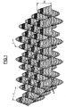
- plane light waves are used, thereby obtaining a sinusoidal microstructure.
- FIG. 1 shows a system of sinusoidal interference fringes crossed at 90 °.
- the microstructure is slightly deformed with respect to the interference pattern but does not have an abrupt discontinuity.
- the pitch i of the microstructure can vary substantially depending on the situation on the corrective surface.
- This deformation can be eliminated by creating an interference fringe pattern itself modified to take into account the curvature of the surface to be carried by the microstructure.
- the hollows of this microstructure can be filled with a material of refractive index lower than that of the microstructure.
- the index difference of the two materials is preferably greater than or equal to 0.1.
- An anti-fouling material is preferably chosen from a hydrophobic material.
- a suitable antifouling material has the formula: where R is an alkyl radical, for example C 1 -C 6 , and n and n 'are integers which can vary independently from 0 to 6.
- the manufacture of organic glass ophthalmic lenses can be done by molding between two parts 2, 4 of a mold 1, connected by fastening elements 5.
- a material or an optical composition is then introduced into the assembly of the mold through an orifice 6, either by casting or by injection, and is cured or polymerized therein, after disassembling the mold, obtaining an ophthalmic lens.
- at least one of the parts of the mold 2, 4 has an internal surface, for example the surface 3, having a corrective geometry of the view.
- the face internal 3 or 3 'of a portion 2 of the mold is provided with a utility microstructure that is to say having optical properties, preferably anti-reflective properties.
- the mold part 2 whose surface 3 comprises the utility microstructure, is formed directly in the mold part.
- the mold part has the microstructured surface with corrective geometry of metal, for example nickel, or plastic.
- the geometry of this microstructure is initially determined by an interference method, for example using the interference fringe figure shown in FIG.
- a first method for producing an integral mold part provided with a microstructured surface with a corrective geometry consists in producing a metal matrix, for example made of nickel, by electroplating as described above. If the matrix is sufficiently thick it can be used directly as part of the mold.
- a second method for producing an integral mold part, provided with a microstructured surface with a corrective geometry consists in depositing on a surface with a corrective geometry the view of a mineral glass substrate a layer of photosensitive resin, and by the interferential method. previously described, to form there the desired microstructure.
- plasma-isotropic bombardment for example an argon-CHF 3 plasma
- the microstructure is transferred into the glass substrate.
- a third method for producing an integral mold part consists in molding a mold part from a mold, one of whose parts comprises a utility microstructure initially produced by an interference process.
- One method for obtaining a composite mold portion, a portion of which has a microstructured corrective geometry surface is the polymerization duplication.
- a layer of a polymerizable resin is deposited on a corrective geometry surface of a substrate.
- the coated substrate is then brought into close contact with a microstructured surface of a matrix, for example of metal (nickel), for example by vacuum application or by pressing.
- a mold part formed of a substrate having a surface with a corrective geometry is provided. desired utility microstructure.
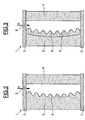
- Figure 3 shows the case where the utility microstructure is carried by an insert 2 ', a surface 3' is provided with the utility microstructure.
- This insert which may be metal, for example nickel, or plastic, can be obtained as indicated above. Since it must be fixed on a surface of the mold part 2 having a corrective geometry of the view, it can be either shaped prior to the desired geometry, or be deformed, for example by stamping, at the time of its installation on the mold part 2 to conform to the geometry of this part. Generally, this insert 2 'is attached to the surface 3 of the mold part 2 by means of an adhesive.
- Obtaining a microstructured ophthalmic lens according to the invention is generally carried out simply by pouring into the mold through the introduction orifice 6 of a liquid composition of optical monomers or by injection of an optical thermoplastic material. After disassembly of the mold, an ophthalmic lens is recovered having a surface carrying a utility microstructure, in particular having anti-reflection properties.
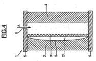
- FIG. 4 shows another embodiment of a mold that can be used in the method of the invention, which is characterized by the fact that it comprises a deformable plane insert 2 'provided on one of its surfaces. a utility microstructure 3 ', preferably having anti-reflective properties.
- This plane insert 2 ' can be deformed during the molding of the ophthalmic lens, by creating a vacuum in the mold 1 on the surface of the the insert opposite the surface 3 'carrying the microstructure, so as to match the geometry of the surface 3 of the mold part 2, generally a corrective geometry of the view.
- this insert 2 ' can be deformed by the pressure exerted by the liquid monomer composition cast in the mold by the insertion orifice 6 or by the optical thermoplastic material injected into the mold through this orifice 6, in this way again, to marry the face with corrective geometry of the view of the part 2 of the mold.
- the deformable insert 2 ' may be an insert of plastic or metallic material, preferably metal, for example nickel.
- An advantage of using such a mold in the process of the invention is that one can form on a flat strip several inserts of similar or different microstructures, cut these inserts and use them in the mold depending on the microstructure desired. In addition, these inserts can be discarded and replaced easily.
- FIG. 5 shows a method for obtaining ophthalmic lenses according to the invention, by transfer molding.
- Figure 5 relates to the technique of coating "in the mold” (In-Mold Coating) well known in the art of manufacturing ophthalmic lenses.
- a layer 8 of an optical material is formed on the mold part 2 having a surface 3 having a corrective geometry of the view and provided with a utility microstructure.
- the microstructure of the mold part 2 is transferred directly into the layer 8.
- a composition or an optical material which is cured or polymerized is introduced either thermally or under the effect of actinic radiation, for example UV radiation.
- an ophthalmic lens is obtained comprising on an optically transparent substrate a microstructured optically transparent layer having the desired corrective geometry.
- mold parts can have any suitable shape, in particular convex, concave or other, depending on the desired corrective geometry.
- the materials constituting the mold parts will be chosen according to the method of polymerization or hardening of the compositions and optical materials used to manufacture the lens or the functional layer on the lens.
- parts of transparent plastic mold will be used in the case of polymerization or curing by means of actinic radiation.
- Example 1 Production of an anti-reflection lens made of diallyl diglycol dicarbonate, resistant to abrasion by an in-mold coating process.
- a nickel insert having a surface having a periodic type microstructure initially resulting from an interference process is bonded to an inner face of a portion of a glass mold.
- the mold obtained is cleaned with acetone and then treated with a solution of fluorohydrocarbide (HCFC) containing 0.26% solid material E-349, a release agent marketed by Chem-Trend Inc.
- HCFC fluorohydrocarbide
- the microstructured face of the mold portion is coated by dipping a layer of a coating composition obtained by alkoxysilane hydrolysis including glycidoxy propyl trimethoxysilane, methyl trimethoxysilane, itaconic acid and colloidal silica.
- the coating composition is precured to a "dust-free" stage, i.e., it is no longer sticky or sticky.
- the portion of the mold coated on its inner side of the microstructure is used to mold the front face of the lens and the conventional mineral glass mold portion (without microstructure) is used to mold the back side of the lens.
- the two mold parts are assembled and held at a distance by a seal and a fastening clip ensures the maintenance of the assembly.
- the mold is then filled with diallyl diglycol dicarbonate (from PPG) containing as catalyst diisopropyl peroxy dicarbonate (also available from PPG).
- the monomeric composition is then thermally cured.
- the mold is disassembled with a suitable tool and a lens is obtained which has abrasion-resistant properties and anti-reflection properties, both superior to an uncoated lens obtained. from a classic mineral glass mold (without microstructure).
- Example 2 Production of an Anti-Reflective Lens, Refractive Index 1.6, Polythiourethane and Resistant to Abrasion by a In-Mold Coating Process.
- a nickel insert provided on one side with a periodic microstructure initially resulting from an interference process is adhered to a surface of a portion of a mineral glass mold.
- the mold is cleaned as in Example 1.
- a coating composition as described in Example 3 of Patent FR-A-93 02649 (glycidoxy propyl trimethoxy silane hydrolyzate, dimethyl diethoxy silane and colloidal silica), is deposited on the microstructured surface by dipping using a coating machine. in the laboratory.
- the coating is precured in the "dust-free" state at a temperature of 80 ° C for 15 minutes.
- the thus coated mold part is used to mold the front face of the lens and the conventional mineral glass mold part (without microstructure) is used to mold the back side of the lens.
- the two mold parts are assembled and held at a distance by a seal and a fastening clip ensures the maintenance of the assembly.
- the mold is then filled with monomer MR6® (marketed by Mitsui-Toatsu Company) containing dibutyltin as a catalyst.
- the monomeric composition is then cured to obtain a 1.6 refractive index polyurethane lens using the following heat-curing cycle in the air: Time (minute) Temperature (° C) O 20 1 32 25 32 33 60 35 80 Removal of the seal. 37 120 39 120 41 75
- the mold is disassembled using a suitable tool to obtain, after post curing at 110 ° C for 3 hours, a lens having scratch-resistant properties in the test of the dyed wool. steel and anti-reflections superior to those of an uncoated lens prepared by a similar method.
- Example 2 is repeated, but using an epoxysilane hydrolyzate coating composition containing colloidal titanium.
- Example 4 Production of a diallyl diglycol dicarbonate plastic mold provided with a microstructure of periodic type.
- Example 2 A mold similar to that of Example 1 is cleaned with acetone. By proceeding as in Example 1, the mold is filled with a composition of diallyl diglycol dicarbonate containing triallyl cyanurate and catalyzed with isopropyl peroxy dicarbonate marketed by PPG Industries. The composition is cured by the following thermal curing cycle: Time (minute) Temperature (° C) 15 46 45 46 30 49 60 49 60 54 45 54 45 58 120 58 45 62.5 45 62.5 60 67.5 45 67.5 60 72 45 72 60 78 60 78
- the mold is disassembled by means of a suitable tool to obtain a substrate provided with a microstructured face.
Abstract
Description
La présente invention concerne, d'une manière générale, un procédé d'obtention d'une lentille ophtalmique comportant une microstructure utilitaire en surface, et plus particulièrement une microstructure anti-reflets.The present invention generally relates to a method for obtaining an ophthalmic lens having a utility microstructure on the surface, and more particularly an antireflection microstructure.
A l'heure actuelle, le moyen le plus couramment utilisé pour conférer des propriétés anti-reflets à des lentilles ophtalmiques, en particulier en verre organique, consiste à déposer sur la lentille une couche ou un système de couches anti-reflets en matériaux minéraux. L'utilisation d'une telle couche anti-reflets en matériaux minéraux présente des inconvénients en ce qu'elle peut modifier les propriétés mécaniques de la lentille obtenue, et plus particulièrement peut modifier les propriétés anti-abrasives des couches dures anti-abrasives également déposées sur la lentille ophtalmique.At present, the most commonly used means for imparting anti-reflective properties to ophthalmic lenses, in particular organic glass, is to deposit on the lens a layer or a system of anti-reflection layers of mineral materials. The use of such an anti-reflection layer made of mineral materials has disadvantages in that it can modify the mechanical properties of the lens obtained, and more particularly can modify the abrasion-resistant properties of the abrasion-resistant hard layers also deposited. on the ophthalmic lens.
La réalisation de propriétés optiques à partir de microstructures en surface est un domaine connu dans le monde de l'optique. Ainsi, le document US-A-5 630 902 décrit le transfert d'une microstructure constituée d'éléments optiques diffractifs dans une couche d'un matériau photopolymérisable déposée sur un substrat en matière plastique par emboutissage, par exemple au moyen d'une matrice en quartz portant la microstructure voulue.The realization of optical properties from surface microstructures is a field known in the world of optics. Thus, US-A-5,630,902 describes the transfer of a microstructure consisting of diffractive optical elements in a layer of a photopolymerizable material deposited on a plastic substrate by stamping, for example by means of a matrix. in quartz carrying the desired microstructure.
Le document US-A-4 013 465 décrit un procédé de réalisation d'une surface ayant une réflexion réduite vis-à-vis du rayonnement électromagnétique, qui consiste à appliquer sur une surface d'un substrat une couche d'un matériau photosensible, à exposer ce matériau à un motif régulier de rayonnement électromagnétique auquel il est sensible et à développer le matériau photosensible, de sorte que la topographie de la surface du matériau développée corresponde aux motifs lumineux, de manière à obtenir une surface ayant une réflexion réduite du rayonnement visible.US-A-4 013 465 discloses a method of producing a surface having a reduced reflection with respect to electromagnetic radiation, which comprises applying to a surface of a substrate a layer of a photosensitive material, to expose this material to a regular pattern of electromagnetic radiation to which it is sensitive and to developing the photosensitive material, so that the topography of the surface of the developed material corresponds to the light patterns, so as to obtain a surface having a reduced reflection of the visible radiation.
Le document GB-A-2 027 441 décrit un procédé de fabrication d'un article comprenant une couche ou corps mis en forme, en matériau plastique, monolithique, constitué de certains polymères réticulés et comportant une ou plusieurs surfaces portant une réplique d'une microstructure, qui consiste à remplir un moule maître portant la microstructure avec une composition fluide coulable, polymérisable par addition au moyen d'un rayonnement, réticulable, oligomérique, ayant à la fois des segments "durs" et "mous", et en exposant la composition coulée à un rayonnement actinique pour ainsi former l'article. Ce document précise que le terme microstructure recouvre des discontinuités, telles que des projections et des indentations, dans la surface, dont le profil varie à partir d'une ligne moyenne ou centrale passant à travers la microstructure de telle sorte que la somme des surfaces embrassées par le profil de surface au-dessus de la ligne soit égale à la somme des surfaces en dessous de la ligne, la ligne étant essentiellement parallèle à la surface normale (portant la microstructure) de l'article. La hauteur de ces déviations varie de ± 0,05 µm à ± 750 µm sur une longueur caractéristique représentative de la surface, par exemple 1 à 30 cm. Le profil moyen ou ligne centrale, peut être plan, concave, convexe, asphérique ou une combinaison de ces formes.GB-A-2 027 441 discloses a method of manufacturing an article comprising a shaped layer or body of monolithic plastics material consisting of certain cross-linked polymers and having one or more surfaces bearing a replica of a microstructure, which comprises filling a microstructure-carrying master mold with a crosslinkable, oligomeric, crosslinkable, radiation-transferable fluidizable composition having both "hard" and "soft" segments, and exposing the cast composition with actinic radiation to thereby form the article. This document specifies that the term microstructure covers discontinuities, such as projections and indentations, in the surface, the profile of which varies from a mean or central line passing through the microstructure such that the sum of the embraced surfaces by the surface profile above the line is equal to the sum of the areas below the line, the line being substantially parallel to the normal surface (carrying the microstructure) of the article. The height of these deviations varies from ± 0.05 μm to ± 750 μm over a representative characteristic length of the surface, for example 1 to 30 cm. The middle profile or central line, can be plane, concave, convex, aspheric or a combination of these forms.
Des articles dans lesquels ces déviations sont d'ordre inférieur, c'est-à-dire de ± 0,005 µm à 0,1 µm ou, de préférence, de ± 0,05 µm, et ces déviations sont peu fréquentes ou d'apparition minimale, c'est-à-dire que la surface est libre de toute discontinuité significative, sont celles pour lesquelles la surface portant la microstructure est une surface "plate" ou "parfaitement lisse". De tels articles sont utiles, par exemple, comme éléments d'optique de précision ou éléments avec un interface optique de précision, tels que des lentilles ophtalmiques. Les articles pour lesquels ces déviations sont d'ordre inférieur mais d'occurence fréquente, sont ceux, par exemple, portant des discontinuités utilitaires, comme dans le cas d'articles ayant une microstructure anti-reflets. Les articles pour lesquels les déviations sont d'ordre élevé, c'est-à-dire de ± 0,1 µm à ± 750 µm, auxquels peut être attribuée une microstructure comprenant un ensemble de discontinuités utilitaires, qui sont identiques ou différentes, espacées ou contiguës, de manière aléatoire ou ordonnée, sont des articles tels que les feuilles rétroflectrices, des lentilles de Fresnel linéaires et des disques vidéo. En outre, ce document mentionne qu'il peut être nécessaire ou souhaitable de choisir les compositions oligomériques particulières dont le retrait au durcissement soit faible pour éviter l'apparition de discontinuités parasites interférant avec les discontinuités utilitaires.Articles in which these deviations are of a lower order, that is, from ± 0.005 μm to 0.1 μm or, preferably, ± 0.05 μm, and such deviations are infrequent or of occurrence minimum, that is to say that the surface is free of any significant discontinuity, are those for which the surface carrying the microstructure is a "flat" or "perfectly smooth" surface. Such articles are useful, for example, as precision optics or elements with a precision optical interface, such as ophthalmic lenses. Articles for which these deviations are of lower order but of frequent occurrence, are those, for example, bearing utility discontinuities, as in the case of articles having an antireflection microstructure. Articles for which deviations are high order, i.e., from ± 0.1 μm to ± 750 μm, to which a microstructure comprising a set of utility discontinuities, which are identical or different, spaced or contiguous, may be assigned, in random or orderly manner, are articles such as retroflecting sheets, linear Fresnel lenses and video disks. In addition, this document mentions that it may be necessary or desirable to choose the particular oligomeric compositions whose curing shrinkage is low to avoid the appearance of parasitic discontinuities interfering with utility discontinuities.
Le brevet US-5,538,674 décrit un procédé de moulage d'un élément en matière plastique portant une microstructure qui consiste à fournir un moule-maître comportant une microstructure; couler un revêtement liquide sur le moule-maître et solidifier le revêtement pour former un outil de moulage rigide comportant la microstructure ; placer l'outil de moulage dans une machine de moulage ; introduire un élément en matière plastique dans la machine de moulage ; transférer la microstructure de l'outil de moulage à l'élément en matière plastique ; et retirer l'élément moulé en matière plastique de la machine de moulage.US-5,538,674 discloses a method of molding a plastic member carrying a microstructure which comprises providing a master mold having a microstructure; casting a liquid coating on the master mold and solidifying the coating to form a rigid molding tool including the microstructure; placing the molding tool in a molding machine; introducing a plastic element into the molding machine; transferring the microstructure of the molding tool to the plastic element; and removing the molded plastic element from the molding machine.
Le brevet US-4,013,465 décrit un procédé de production d'une surface ayant une réflectance réduite vis-à-vis du rayonnement électromagnétique pour une bande de longueur d'onde prédéterminée qui comprend l'agencement sur la surface d'un réseau régulier de protubérances ayant une hauteur qui n'est pas inférieure à un tiers de la longueur de la plus grande longueur d'onde de la bande et un espacement qui est inférieure à la longueur de la plus courte longueur d'onde de la bande divisée par l'indice de réfraction du matériau des protubérances. Le réseau de protubérances peut être réalisé en déposant une couche d'un matériau photosensible, exposant le matériau à un motif régulier de rayonnement électromagnétique et en développant le matériau photosensible.U.S. Patent 4,013,465 discloses a method of producing a surface having a reduced reflectance to electromagnetic radiation for a predetermined wavelength band which comprises arranging on the surface of a regular array of protuberances having a height that is not less than one-third of the length of the longest wavelength of the band and a spacing that is less than the length of the shortest wavelength of the band divided by the refractive index of the material of the protuberances. The array of protuberances can be made by depositing a layer of a photosensitive material, exposing the material to a regular pattern of electromagnetic radiation and developing the photosensitive material.
La présente invention a donc pour objet un procédé d'obtention d'une lentille ophtalmique, c'est-à-dire un article ayant une géométrie correctrice de la vue, comportant en surface une microstructure utilitaire, c'est-à-dire ayant des propriétés optiques, en particulier des propriétés anti-reflets, la géométrie de la microstructure utilitaire étant initialement déterminée par un procédé interférentiel.The present invention therefore relates to a method for obtaining an ophthalmic lens, that is to say an article having a corrective geometry of the view, having on the surface a utilitarian microstructure, that is to say having optical properties, in particular anti-reflection properties, the geometry of the utility microstructure being initially determined by an interference method.
La présente invention a également pour objet les lentilles ainsi obtenues comportant une surface à géométrie correctrice de la vue, pourvue d'une microstructure utilitaire , ayant des propriétés anti-reflets, dont la géométrie est initialement déterminée par un procédé interférentiel.The subject of the present invention is also the lenses thus obtained comprising a surface with a corrective geometry of the sight, provided with a utility microstructure, having anti-reflection properties, whose geometry is initially determined by an interference method.
Cette microstructure utilitaire est réalisée dans une couche fonctionnelle superficielle de la lentille ophtalmique qui, après durcissement, constitue un revêtement dur ayant des propriétés de résistance à l'abrasion.This utilitarian microstructure is made in a surface functional layer of the ophthalmic lens which, after curing, constitutes a hard coating having abrasion-resistant properties.
Selon l'invention, le procédé d'obtention d'une lentille ophtalmique comportant en surface une microstructure utilitaire anti-reflets comprend une étape de transfert de la microstructure à partir d'un moule dont une surface interne porte la microstructure et possède une géométrie correctrice de la vue, la géométrie de la microstructure étant initialement déterminée par un procédé interférentiel, et l'étape de transfert consiste à :
- former dans le moule une couche d'un premier matériau optique durcissable dont une surface porte une réplique de la microstructure portée par la face interne du moule ;
- faire durcir dans le moule la couche durcie du premier matériau optique,
l'étape de transfert étant caractérisée en ce que ledit premier matériau optique forme, après durcissement, un revêtement dur ayant des propriétés de résistance à l'abrasion, et en ce qu'elle consiste en outre à:- introduire entre la surface de la couche durcie du premier matériau optique, opposée à la surface portant la microstructure et une paroi du moule, un second matériau optique durcissable ;
- faire durcir le second matériau optique ; et
- désassembler le moule pour récupérer une lentille ophtalmique comportant un substrat formé du second matériau optique dont une surface est recouverte de la couche durcie du premier matériau optique portant la microstructure utilitaire.
- forming in the mold a layer of a first curable optical material whose surface bears a replica of the microstructure carried by the inner face of the mold;
- hardening in the mold the hardened layer of the first optical material,
the transfer step being characterized in that said first optical material forms, after curing, a hard coating having abrasion-resistant properties, and further comprising:- introducing between the surface of the cured layer of the first optical material, opposite the surface carrying the microstructure and a wall of the mold, a second curable optical material;
- hardening the second optical material; and
- disassembling the mold to recover an ophthalmic lens having a substrate formed of the second optical material whose surface is covered with the cured layer of the first optical material carrying the utility microstructure.
De préférence, la surface à géométrie correctrice de la vue est une surface à géométrie progressive. En général, la courbure de la surface à géométrie progressive du moule a un rayon de courbure mesuré en un point quelconque de la surface correctrice compris entre 40 mm et 100 mm.Preferably, the corrective geometry surface of the view is a surface with a progressive geometry. In general, the curvature of the surface of progressive mold geometry has a radius of curvature measured at any point of the corrective surface between 40 mm and 100 mm.
On peut utiliser dans le procédé de la présente invention tous types de moulage classiques pour la fabrication de lentilles ophtalmiques, tels que le moulage direct, par exemple au moyen d'un moule intégral ou au moyen d'un moule composite à élément rapporté ou à insert, ou encore par surmoulage, et les moulages dits "par transfert", par exemple par emboutissage, ou par la méthode bien connue dans l'optique ophtalmique du transfert par "revêtement dans le moule" ("In-Mold Coating").It is possible to use in the method of the present invention all conventional molding types for the manufacture of ophthalmic lenses, such as direct molding, for example by means of an integral mold or by means of a composite mold with insert or insert, or by overmoulding, and the so-called molding "transfer", for example by stamping, or by the well-known method in the ophthalmic optics of the transfer by "coating in the mold"("In-MoldCoating").
Dans une première réalisation de l'invention, le moule utilisé est un moule intégral, c'est-à-dire que la microstructure utilitaire est formée directement dans une surface interne du moule possédant la géométrie correctrice de la vue requise. Le moule peut être en matière plastique, en verre minéral ou en métal, en particulier en nickel.In a first embodiment of the invention, the mold used is an integral mold, that is to say that the utility microstructure is formed directly in an inner surface of the mold having the corrective geometry of the required view. The mold may be made of plastic, mineral glass or metal, in particular nickel.
Dans une seconde réalisation de l'invention, le moule est un moule composite qui comprend un élément rapporté ayant une surface dans laquelle est formée la microstructure utilitaire, cet élément rapporté épousant la surface du moule présentant la géométrie correctrice de la vue, de sorte que la surface de l'élément rapporté comportant la microstructure utilitaire ait également la géométrie correctrice de la vue voulue. L'élément rapporté peut être initialement conformé pour présenter la géométrie correctrice de la vue voulue et être fixé à la surface correspondante du moule, par exemple au moyen d'un adhésif. L'élément rapporté peut également avoir initialement une forme plane et être ensuite déformé pour épouser la surface à géométrie correctrice de la vue du moule. Dans ce dernier cas, l'élément rapporté peut également se fixer à la surface à géométrie correctrice de la vue du moule au moyen d'un adhésif. Lorsque l'élément rapporté portant la microstructure est un élément en matière plastique destiné à être appliqué sur une surface d'un moule, cet élément doit posséder un minimum d'élasticité dans le plan pour pouvoir être convenablement appliqué. Des éléments appropriés de ce type sont des éléments en polyuréthanne ayant par exemple un module d'Young mesuré à 30°C de 1,2 Giga Pascals. De manière générale, les éléments appropriés ont un module d'Young inférieur à 2,5 Giga Pascals.In a second embodiment of the invention, the mold is a composite mold which comprises an insert having a surface in which the utility microstructure is formed, said insert matching the surface of the mold having the corrective geometry of the view, so that the surface of the insert including the utility microstructure also has the corrective geometry of the desired view. The insert can be initially shaped to present the correct view of the desired geometry and be attached to the corresponding surface of the mold, for example by means of an adhesive. The insert may also initially have a planar shape and then be deformed to conform to the corrective geometry surface of the mold view. In the latter case, the insert can also be attached to the corrective geometry surface of the mold view by means of an adhesive. When the insert carrying the microstructure is a plastic element intended to be applied to a surface of a mold, this element must have a minimum of elasticity in the plane in order to be properly applied. Suitable elements of this type are polyurethane elements having, for example, a Young's modulus measured at 30 ° C. of 1.2 Giga Pascals. In general, the appropriate elements have a Young's modulus of less than 2.5 Giga Pascals.
Enfin, l'élément rapporté peut être constitué par une couche de matériau, tel qu'une matière plastique formée directement sur une surface d'un substrat.Finally, the insert may be a layer of material, such as a plastic material formed directly on a surface of a substrate.
Dans une troisième réalisation de l'invention, le moule est un moule composite qui comprend un insert plan pourvu sur une de ses surfaces de la microstructure utilitaire, cet insert plan étant déformé dans le moule pour épouser la surface à géométrie correctrice de la vue du moule par application dans le moule d'une pression ou d'un vide.In a third embodiment of the invention, the mold is a composite mold which comprises a planar insert provided on one of its surfaces with the utility microstructure, this planar insert being deformed in the mold to fit the corrective geometry surface of the mold view by application in the mold of a pressure or a hole.
On peut utiliser dans le procédé d'obtention de lentilles ophtalmiques selon l'invention, tous matériaux ou compositions optiques, durcissables thermiquement ou au moyen d'un rayonnement actinique, en particulier au moyen d'un rayonnement UV, qui peut être coulé ou injecté dans le moule, et qui conduit à des lentilles ophtalmiques ayant la transparence optique voulue et les propriétés mécaniques voulues. Ces matériaux ou compositions optiques comprennent non seulement les matériaux et compositions servant à fabriquer la lentille ophtalmique elle-même, mais également les matériaux et compositions permettant le dépôt de couches fonctionnelles particulières sur une lentille ophtalmique, tels que les matériaux destinés à la formation d'une couche anti-abrasion sur une lentille ophtalmique.In the process for obtaining ophthalmic lenses according to the invention, it is possible to use any material or optical composition that can be thermally curable or by means of actinic radiation, in particular by means of UV radiation, which can be cast or injected. in the mold, and which leads to ophthalmic lenses having the desired optical transparency and the desired mechanical properties. These optical materials or compositions comprise not only the materials and compositions used to manufacture the ophthalmic lens itself, but also the materials and compositions for the deposition of particular functional layers on an ophthalmic lens, such as materials intended for the formation of ophthalmic lenses. an anti-abrasion layer on an ophthalmic lens.
De préférence, le matériau ou la composition optique est un matériau thermoplastique ou une composition liquide de monomères durcissables thermiquement ou au moyen d'un rayonnement actinique. Les compositions liquides de monomères sont particulièrement recommandées dans le procédé de l'invention.Preferably, the optical material or composition is a thermoplastic material or a liquid composition of thermally curable monomers or by means of actinic radiation. Liquid monomer compositions are particularly recommended in the process of the invention.
Parmi les monomères utiles dans les compositions de monomères optiques utilisables dans le procédé de la présente invention, on peut citer les (méth)acrylates d'alkyle, en particulier les (méth)acrylates d'alkyle en C1-C4 tels que le méthyl(méth)acrylate et l'éthyl(méth)acrylate, les dérivés allyliques tels que les allyl carbonates de polyols aliphatiques ou aromatiques, linéaires ou ramifiés et les dérivés thio(méth)acryliques.Among the monomers useful in the optical monomer compositions that may be used in the process of the present invention, mention may be made of alkyl (meth) acrylates, in particular (C 1 -C 4 ) alkyl (meth) acrylates such as methyl (meth) acrylate and ethyl (meth) acrylate, allyl derivatives such as allyl carbonates of linear or branched aliphatic or aromatic polyols and thio (meth) acrylic derivatives.
Des monomères particulièrement recommandés dans le procédé de l'invention sont les allyl carbonates de polyols parmi lesquels on peut citer l'éthylèneglycol bis allyl carbonate, le diéthylène glycol bis 2-méthyl carbonate, le diéthylène glycol bis(allyl carbonate), l'éthylène glycol bis (2-chloro allyl carbonate), le triéthylène glycol bis(allyl carbonate), le 1,3-propane diol bis(allyl carbonate), le propylène glycol bis (2-éthyl allyl carbonate), le 1,3-butane diol bis(allyl carbonate), le 1,4-butane diol bis (2-bromo allyl carbonate), le dipropylène glycol bis(allyl carbonate), le triméthylène glycol bis(2-éthyl allyl carbonate), le pentaméthylène glycol bis(allyl carbonate), l'isopropylène bisphénol-A bis(allyl carbonate). Un monomère particulièrement recommandé est le diéthylène glycol bis(allyl carbonate).Particularly preferred monomers in the process of the invention are allyl carbonates of polyols, among which mention may be made of ethylene glycol bis allyl carbonate, diethylene glycol bis 2-methyl carbonate, diethylene glycol bis (allyl carbonate), ethylene glycol bis (2-chloro allyl carbonate), triethylene glycol bis (allyl carbonate), 1,3-propane diol bis (allyl carbonate), propylene glycol bis (2-ethyl allyl carbonate), 1,3-butane diol bis (allyl carbonate), the 1,4-butane diol bis (2-bromo allyl carbonate), dipropylene glycol bis (allyl carbonate), trimethylene glycol bis (2-ethyl allyl carbonate), pentamethylene glycol bis (allyl carbonate), isopropylene bisphenol A bis (allyl carbonate). A particularly preferred monomer is diethylene glycol bis (allyl carbonate).
Une autre classe de monomères convenant pour les compositions utilisables dans le procédé de la présente invention, comprend les (méth) acrylates aromatiques polyéthoxylés tels que les bis phénol-A diméthacrylate polyéthoxylés, en particulier ceux décrits dans la demande de brevet français FR-A-2 699 541.Another class of monomers suitable for the compositions that can be used in the process of the present invention comprises polyethoxylated aromatic (meth) acrylates such as polyethoxylated bisphenol-A dimethacrylates, in particular those described in the French patent application FR-A- 2,699,541.
On peut également utiliser les monomères thio(méth) acryliques, en particulier ceux décrits dans la demande de brevet français FR-A-2 734 827.It is also possible to use the thio (meth) acrylic monomers, in particular those described in the French patent application FR-A-2 734 827.
On peut également utiliser des compositions à base de polythiols et de polyisocyanates sous forme monomérique, conduisant à des polythiouréthannes tels que décrits notamment dans le brevet US 4 689 387.It is also possible to use compositions based on polythiols and polyisocyanates in monomeric form, resulting in polythiourethanes as described in particular in US Pat. No. 4,689,387.
Enfin, on peut utiliser des compositions renfermant un ou plusieurs monomères di- ou polythiol avec un ou plusieurs monomères porteurs de groupements insaturés réactifs avec des fonctions thiols, tels que les groupements vinyliques, (méth)acryliques et thio(méth) acryliques.Finally, it is possible to use compositions containing one or more di- or polythiol monomers with one or more monomers bearing unsaturated groups reactive with thiol functions, such as vinyl, (meth) acrylic and thio (meth) acrylic groups.
Bien évidemment, les compositions de monomères peuvent comprendre des mélanges des monomères ci-dessus.Of course, the monomer compositions may comprise mixtures of the above monomers.
On a remarqué que plus l'indice de réfraction de la couche comportant la microstructure est élevé, plus l'effet anti-reflet est prononcé. De ce fait, l'indice de la couche microstructurée est de préférence égal ou supérieur à 1,55, mieux égal à 1,6 ou plus. Il est bien évident que cette couche microstructurée peut être constituée par le verre organique ou par une couche superficielle telle qu'un revêtement anti-abrasion déposée sur une surface d'un substrat en verre organique.It has been noted that the higher the refractive index of the layer comprising the microstructure, the greater the anti-reflection effect is pronounced. As a result, the index of the microstructured layer is preferably equal to or greater than 1.55, more preferably 1.6 or more. It is obvious that this microstructured layer may consist of organic glass or a surface layer such as an anti-abrasion coating deposited on a surface of an organic glass substrate.
Parmi les matériaux thermoplastiques utiles dans le procédé de l'invention, on peut citer les prépolymères et polymères thermoplastiques tels que les polycarbonates thermoplastiques.Among the thermoplastic materials useful in the process of the invention, mention may be made of thermoplastic prepolymers and polymers such as thermoplastic polycarbonates.
Selon le procédé de l'invention, la microstructure utilitaire est impartie, non pas dans la lentille ophtalmique elle-même, mais dans un revêtement fonctionnel anti-abrasion déposé sur cette lentille. On peut utiliser dans le procédé de la présente invention, toutes compositions de monomères durcissables convenant pour former sur une lentille ophtalmique une couche anti-abrasion.According to the method of the invention, the Utility microstructure is imparted, not in the ophthalmic lens itself, but in an anti-abrasion functional coating deposited on this lens. Any curable monomer compositions suitable for forming an anti-abrasion layer on an ophthalmic lens can be used in the process of the present invention.
Parmi ces compositions durcissables résistant à l'abrasion, on peut citer les compositions à base d'hydrolysat de silane, en particulier d'hydrolysat d'époxysilane telles que celles décrites dans la demande de brevet français n° 93 026 49, et les compositions à base de dérivés acryliques.Among these curable compositions resistant to abrasion, mention may be made of compositions based on silane hydrolyzate, in particular epoxysilane hydrolyzate such as those described in French Patent Application No. 93 026 49, and the compositions based on acrylic derivatives.
Bien évidemment, les matériaux et compositions optiques utiles dans le procédé de la présente invention peuvent comporter tous adjuvants classiquement utilisés dans la fabrication des lentilles ophtalmiques, et en particulier des initiateurs et catalyseurs de polymérisation thermique et/ou photochimique.Of course, the optical materials and compositions useful in the process of the present invention may comprise any adjuvants conventionally used in the manufacture of ophthalmic lenses, and in particular initiators and catalysts for thermal and / or photochemical polymerization.
Comme indiqué, la géométrie de la microstructure utilitaire est initialement déterminée par un procédé interférentiel, c'est-à-dire que la microstructure utilitaire est soit formée directement sur la surface du moule par un procédé interférentiel, soit est obtenue par transfert à partir d'une matrice dont une surface comporte une microstructure utilitaire obtenue par un procédé interférentiel.As indicated, the geometry of the utility microstructure is initially determined by an interference method, i.e. the utility microstructure is either formed directly on the mold surface by an interference method, or is obtained by transfer from a matrix whose surface comprises a utility microstructure obtained by an interference method.
Plus précisément, le procédé interférentiel consiste à réaliser une figure de franges d'interférences par superposition de deux ondes lumineuses cohérentes, par exemple deux faisceaux lasers, et à irradier une couche de matériau photosensible déposée sur un substrat au moyen de cette figure de franges d'interférences.More specifically, the interference method consists in producing an interference fringe pattern by superposing two coherent light waves, for example two laser beams, and irradiating a layer of photosensitive material deposited on a substrate by means of this fringe pattern. interference.
En développant ensuite, de manière classique, la couche de matériau photosensible, on obtient une microstructure périodique.By then developing, in a conventional manner, the layer of photosensitive material, a periodic microstructure is obtained.
On peut prévoir deux étapes d'irradiation de la couche photosensible en ayant fait tourner le substrat, de préférence de 90° après la première étape d'irradiation, et on développe ensuite de manière classique la couche de matériau photosensible.Two steps of irradiating the photosensitive layer can be provided by rotating the substrate, preferably 90 ° after the first irradiation step, and then developing the layer of photosensitive material.
On obtient alors une microstructure périodique dans le plan. On peut ainsi obtenir une structure isotrope dont les propriétés anti-reflets sont indépendantes de l'angle de vision.We then obtain a periodic microstructure in the plane. We can thus obtain an isotropic structure whose anti-reflective properties are independent of the viewing angle.
Bien évidemment, on peut utiliser des figures de franges d'interférence ayant des pas (i) et des amplitudes (2A) différentes ou identiques. On peut également répéter plusieurs fois les étapes d'irradiations pour ainsi obtenir après développement une microstructure finale constituée de plusieurs microstructures superposées.Of course, it is possible to use interference fringe figures having different or identical steps (i) and amplitudes (2A). The irradiation steps can also be repeated several times to thereby obtain, after development, a final microstructure consisting of several superimposed microstructures.
Généralement, la longueur d'onde des faisceaux lumineux cohérents, par exemple des faisceaux lasers, est comprise entre 170 et 510 nm et le pas de la figure de franges d'interférences (et par conséquent de la microstructure périodique obtenue) est compris entre 100 et 300 nm. L'amplitude 2A est généralement comprise entre 100 et 300 nm.Generally, the wavelength of the coherent light beams, for example laser beams, is between 170 and 510 nm and the pitch of the interference fringe pattern (and consequently of the obtained periodic microstructure) is between 100 and 300 nm. The
De préférence, on utilise des ondes lumineuses planes, et on obtient ainsi une microstructure sinusoïdale.Preferably, plane light waves are used, thereby obtaining a sinusoidal microstructure.
La microstructure périodique peut être définie dans un repère orthonormé (x, y, z) de manière générale par l'équation (1) suivante : 
où An, Bn sont les coefficients de Fourier de la microstructure dans la direction x ;
Cm, Dm sont les coefficients de Fourier de la microstructure dans la direction y ; et
i est le pas (période) de la microstructure.The periodic microstructure can be defined in an orthonormal frame (x, y, z) generally by the following equation (1):
where A n , B n are the Fourier coefficients of the microstructure in the x direction;
C m , D m are the Fourier coefficients of the microstructure in the y direction; and
i is the step (period) of the microstructure.
De préférence, on considère Bn = Dm = o, An = Cm = A (structure sinusoïdale)
et la figure de franges d'interférences et par conséquent la microstructure peut être représentée par l'équation (2) :
où i est la période et A la demi amplitude.Preferably, B n = D m = 0, A n = C m = A (sinusoidal structure)
and the figure of interference fringes and therefore the microstructure can be represented by equation (2):
where i is the period and A is half amplitude.
On a représenté, à la figure 1, un système de franges d'interférences sinusoïdales croisées à 90°.FIG. 1 shows a system of sinusoidal interference fringes crossed at 90 °.
Tout ce qui a été défini précédemment concerne le cas où la figure de franges d'interférences est supportée par une surface plane.All that has been defined above concerns the case where the interference fringe figure is supported by a flat surface.
Dans le cas d'une surface courbe, la microstructure est légèrement déformée par rapport à la figure d'interférence mais ne comporte pas de discontinuité abrupte.In the case of a curved surface, the microstructure is slightly deformed with respect to the interference pattern but does not have an abrupt discontinuity.
En particulier, le pas i de la microstructure peut sensiblement varier en fonction de la situation sur la surface correctrice.In particular, the pitch i of the microstructure can vary substantially depending on the situation on the corrective surface.
On peut éliminer cette déformation en créant une figure de franges d'interférences elle-même modifiée pour tenir compte de la courbure de la surface devant porter la microstructure.This deformation can be eliminated by creating an interference fringe pattern itself modified to take into account the curvature of the surface to be carried by the microstructure.
Afin d'éviter que les creux de la microstructure utilitaire, et en particulier anti-reflets, retiennent les salissures et les graisses, on peut combler les creux de cette microstructure avec un matériau d'indice de réfraction inférieur à celui de la microstructure. La différence d'indice des deux matériaux est de préférence supérieure ou égale à 0,1.In order to prevent the hollows of the utilitarian microstructure, and in particular anti-reflections, from retaining soiling and grease, the hollows of this microstructure can be filled with a material of refractive index lower than that of the microstructure. The index difference of the two materials is preferably greater than or equal to 0.1.
On choisira de préférence comme matériau anti-salissures un matériau hydrophobe.An anti-fouling material is preferably chosen from a hydrophobic material.
Un matériau anti-salissures convenable répond à la formule :

où R est un radical alkyle, par exemple en C1-C6,
et n et n' sont des entiers pouvant varier indépendamment de 0 à 6.A suitable antifouling material has the formula:
where R is an alkyl radical, for example C 1 -C 6 ,
and n and n 'are integers which can vary independently from 0 to 6.
La suite de la description se réfère aux figures annexées, qui représentent respectivement :
- Figure 1 - une représentation théorique d'un système de franges d'interférences sinusoïdales croisées à 90° utilisable pour former la microstructure selon l'invention ;
- Figure 2 - une vue schématique d'un moule intégral utilisable dans un procédé d'obtention d'une lentille ophtalmique selon l'invention ;
- Figure 3 - une vue schématique d'un moule à éléments rapportés utilisable dans le procédé d'obtention d'une lentille ophtalmique selon l'invention ;
- Figure 4 - une vue schématique d'un moule comportant un insert déformable, utilisable dans le procédé d'obtention d'une lentille selon l'invention ;
- Figure 5 - une vue schématique d'un moule utilisable pour l'obtention d'une lentille ophtalmique selon l'invention, par un procédé de « revêtement dans le moule » (In-Mold Coating) ; et
- Figure 6 - un graphe du pourcentage de réflexion d'une lentille microstructurée selon l'invention et d'une lentille classique (sans microstructure) en fonction de la longueur d'onde de la lumière.
- FIG. 1 is a theoretical representation of a system of sinusoidal interference fringes crossed at 90 ° which can be used to form the microstructure according to the invention;
- Figure 2 - a schematic view of an integral mold used in a process for obtaining an ophthalmic lens according to the invention;
- Figure 3 - a schematic view of a mold with inserts used in the process for obtaining an ophthalmic lens according to the invention;
- FIG. 4 is a schematic view of a mold comprising a deformable insert that can be used in the process for obtaining a lens according to the invention;
- Figure 5 - a schematic view of a mold used to obtain an ophthalmic lens according to the invention, by a process of "coating in the mold" (In-Mold Coating); and
- Figure 6 - a graph of the reflection percentage of a microstructured lens according to the invention and a conventional lens (without microstructure) as a function of the wavelength of the light.
Sur les figures, les mêmes éléments sont identifiés par les mêmes numéros de référence.In the figures, the same elements are identified by the same reference numbers.
En se référant aux figures 2 à 4, la fabrication de lentilles ophtalmiques en verre organique peut se faire par moulage entre deux parties 2, 4 d'un moule 1, reliées par des éléments de fixation 5. Un matériau ou une composition optique est alors introduit dans l'assemblage du moule par un orifice 6, soit par coulage, soit par injection, et y est durci ou polymérisé pour, après désassemblage du moule, obtenir une lentille ophtalmique. Généralement, au moins une des parties du moule 2, 4 comporte une surface interne, par exemple la surface 3, ayant une géométrie correctrice de la vue.With reference to FIGS. 2 to 4, the manufacture of organic glass ophthalmic lenses can be done by molding between two
Selon l'invention, comme le montrent les figures 2 et 3, la face interne 3 ou 3' d'une partie 2 du moule est pourvue d'une microstructure utilitaire c'est-à-dire ayant des propriétés optiques, de préférence des propriétés anti-reflets.According to the invention, as shown in FIGS. 2 and 3, the face internal 3 or 3 'of a
Dans la réalisation représentée à la figure 2, la partie de moule 2, dont la surface 3 comporte la microstructure utilitaire, est formée directement dans la partie de moule. La partie de moule comporte la surface microstructurée à géométrie correctrice en métal, par exemple en nickel, ou en matière plastique. La géométrie de cette microstructure est initialement déterminée par un procédé interférentiel, par exemple en utilisant la figure de franges d'interférences représentée à la figure 1.In the embodiment shown in FIG. 2, the
Une première méthode pour réaliser une partie de moule intégral pourvue d'une surface microstructurée à géométrie correctrice consiste à réaliser une matrice métallique, par exemple en nickel, par galvanoplastie comme décrit ci-dessus. Si la matrice est suffisamment épaisse on peut l'utiliser directement comme partie de moule.A first method for producing an integral mold part provided with a microstructured surface with a corrective geometry consists in producing a metal matrix, for example made of nickel, by electroplating as described above. If the matrix is sufficiently thick it can be used directly as part of the mold.
Une deuxième méthode pour réaliser une partie de moule intégral, pourvue d'une surface microstructurée à géométrie correctrice consiste à déposer sur une surface à géométrie correctrice de la vue d'un substrat de verre minéral une couche de résine photosensible, et par le procédé interférentiel précédemment décrit, à y former la microstructure voulue. Par bombardement plasma-isotrope (par exemple un plasma argon-CHF3) de la couche durcie, on transfère la microstructure dans le substrat en verre. Un tel procédé de transfert est décrit dans le brevet FR-A-2 663 431.A second method for producing an integral mold part, provided with a microstructured surface with a corrective geometry, consists in depositing on a surface with a corrective geometry the view of a mineral glass substrate a layer of photosensitive resin, and by the interferential method. previously described, to form there the desired microstructure. By plasma-isotropic bombardment (for example an argon-CHF 3 plasma) of the hardened layer, the microstructure is transferred into the glass substrate. Such a transfer method is described in patent FR-A-2,663,431.
Une troisième méthode pour réaliser une partie de moule intégral consiste à effectuer le moulage d'une partie de moule à partir d'un moule dont une des parties comporte une microstructure utilitaire initialement réalisée par un procédé interférentiel.A third method for producing an integral mold part consists in molding a mold part from a mold, one of whose parts comprises a utility microstructure initially produced by an interference process.
Il est également possible de former directement la microstructure utilitaire sur une surface d'une partie d'un moule composite à géométrie correctrice. Dans ce cas, on dépose une couche de résine photosensible sur la surface à géométrie correctrice de la partie de moule, et par le procédé décrit précédemment qui consiste à former des interférences lumineuses sur la résine puis à développer celles-ci, on obtient le motif de microstructure souhaité dans la résine.It is also possible to directly form the utility microstructure on a surface of a portion of a composite mold with corrective geometry. In this case, a layer of photosensitive resin is deposited on the surface with a corrective geometry of the mold part, and by the method described above, which consists in forming light interferences on the resin and then developing these, the pattern is obtained. desired microstructure in the resin.
Une méthode pour obtenir une partie de moule composite dont une partie a une surface à géométrie correctrice microstructurée, est la duplication par polymérisation. Sur une surface à géométrie correctrice d'un substrat, on dépose une couche d'une résine polymérisable. On vient ensuite mettre en contact étroit le substrat enduit avec une surface microstructurée d'une matrice, par exemple en métal (nickel), par exemple par application de vide ou par pressage. Après polymérisation soit thermique, soit photochimique (rayonnement UV) au travers du substrat enduit (selon la nature de la couche de résine) et désassemblage, on obtient une partie de moule formée d'un substrat dont une surface à géométrie correctrice est pourvue de la microstructure utilitaire voulue.One method for obtaining a composite mold portion, a portion of which has a microstructured corrective geometry surface, is the polymerization duplication. On a corrective geometry surface of a substrate, a layer of a polymerizable resin is deposited. The coated substrate is then brought into close contact with a microstructured surface of a matrix, for example of metal (nickel), for example by vacuum application or by pressing. After thermal or photochemical polymerization (UV radiation) through the coated substrate (depending on the nature of the resin layer) and disassembly, a mold part formed of a substrate having a surface with a corrective geometry is provided. desired utility microstructure.
La figure 3 représente le cas où la microstructure utilitaire est portée par un élément rapporté 2' dont une surface 3' est pourvue de la microstructure utilitaire. Cet élément rapporté, qui peut être en métal, par exemple en nickel, ou en matière plastique, peut être obtenu comme indiqué précédemment. Etant donné qu'il doit être fixé sur une surface de la partie 2 de moule ayant une géométrie correctrice de la vue, il peut être soit mis en forme préalablement à la géométrie voulue, soit être déformé, par exemple par emboutissage, au moment de son installation sur la partie 2 de moule pour se conformer à la géométrie de cette partie. Généralement, cet élément rapporté 2' est fixé à la surface 3 de la partie 2 de moule au moyen d'un adhésif.Figure 3 shows the case where the utility microstructure is carried by an insert 2 ', a
L'obtention d'une lentille ophtalmique microstructurée selon l'invention s'effectue généralement simplement par coulage dans le moule par l'orifice d'introduction 6 d'une composition liquide de monomères optiques ou par injection d'un matériau thermoplastique optique. Après désassemblage du moule, on récupère une lentille ophtalmique ayant une surface portant une microstructure utilitaire, en particulier ayant des propriétés anti-reflets.Obtaining a microstructured ophthalmic lens according to the invention is generally carried out simply by pouring into the mold through the introduction orifice 6 of a liquid composition of optical monomers or by injection of an optical thermoplastic material. After disassembly of the mold, an ophthalmic lens is recovered having a surface carrying a utility microstructure, in particular having anti-reflection properties.
On a représenté sur la figure 4 une autre réalisation d'un moule utilisable dans le procédé de l'invention, qui se caractérise par le fait qu'il comprend un insert plan 2' déformable, pourvu sur l'une de ses surfaces d'une microstructure utilitaire 3', de préférence ayant des propriétés anti-reflets. Cet insert plan 2' peut être déformé lors du moulage de la lentille ophtalmique, par création d'un vide dans le moule 1 sur la surface de l'insert opposée à la surface 3' portant la microstructure, de manière à épouser la géométrie de la surface 3 de la partie de moule 2, généralement une géométrie correctrice de la vue. En variante, cet insert 2' peut être déformé par la pression exercée par la composition liquide de monomères coulée dans le moule par l'orifice d'introduction 6 ou par le matériau thermoplastique optique injecté dans le moule par cet orifice 6, de manière là encore, à épouser la face à géométrie correctrice de la vue de la partie 2 du moule.FIG. 4 shows another embodiment of a mold that can be used in the method of the invention, which is characterized by the fact that it comprises a deformable plane insert 2 'provided on one of its surfaces. a
L'insert déformable 2'peut être un insert en matière plastique ou métallique, de préférence métallique, par exemple en nickel.The deformable insert 2 'may be an insert of plastic or metallic material, preferably metal, for example nickel.
Un avantage de l'utilisation d'un tel moule dans le procédé de l'invention est qu'on peut former sur une bande plane plusieurs inserts de microstructures analogues ou différentes, découper ces inserts et les utiliser dans le moule en fonction de la microstructure voulue. En outre, ces inserts peuvent être jetés et remplacés facilement.An advantage of using such a mold in the process of the invention is that one can form on a flat strip several inserts of similar or different microstructures, cut these inserts and use them in the mold depending on the microstructure desired. In addition, these inserts can be discarded and replaced easily.
On a représenté à la figure 5 un procédé d'obtention de lentilles ophtalmiques selon l'invention, par moulage par transfert.FIG. 5 shows a method for obtaining ophthalmic lenses according to the invention, by transfer molding.
La figure 5 concerne la technique de revêtement "dans le moule" (In-Mold Coating) bien connue dans la technique de fabrication des lentilles ophtalmiques.Figure 5 relates to the technique of coating "in the mold" (In-Mold Coating) well known in the art of manufacturing ophthalmic lenses.
Dans cette technique, une couche 8 d'un matériau optique, selon l'invention, une couche de matériau dur anti-abrasion, est formée sur la partie 2 de moule comportant une face 3 à géométrie correctrice de la vue et pourvue d'une microstructure utilitaire. Ainsi, la microstructure de la partie de moule 2 se trouve transférée directement dans la couche 8. Ensuite, on introduit par l'orifice 6 du moule, par coulage ou injection, une composition ou un matériau optique que l'on fait durcir ou polymériser, soit thermiquement, soit sous l'effet d'un rayonnement actinique, par exemple un rayonnement UV. Après désassemblage du moule, on obtient une lentille ophtalmique comportant sur un substrat optiquement transparent une couche optiquement transparente microstructurée ayant la géométrie correctrice voulue.In this technique, a layer 8 of an optical material, according to the invention, a layer of abrasion resistant hard material, is formed on the
Il est bien entendu que les parties de moule peuvent avoir toutes formes appropriées, en particulier convexe, concave ou autres, selon la géométrie correctrice voulue.It is understood that the mold parts can have any suitable shape, in particular convex, concave or other, depending on the desired corrective geometry.
Bien évidemment, les matériaux constituant les parties de moule seront choisis en fonction du procédé de polymérisation ou durcissement des compositions et matériaux optiques utilisés pour fabriquer la lentille ou la couche fonctionnelle sur la lentille. Ainsi, on utilisera des parties de moule en matière plastique transparente dans le cas d'une polymérisation ou durcissement au moyen d'un rayonnement actinique.Of course, the materials constituting the mold parts will be chosen according to the method of polymerization or hardening of the compositions and optical materials used to manufacture the lens or the functional layer on the lens. Thus, parts of transparent plastic mold will be used in the case of polymerization or curing by means of actinic radiation.
Les exemples suivants illustrent la présente invention.The following examples illustrate the present invention.
Un élément rapporté en nickel ayant une surface pourvue d'une microstructure de type périodique résultant initialement d'un procédé interférentiel, est collé sur une face interne d'une partie d'un moule en verre.A nickel insert having a surface having a periodic type microstructure initially resulting from an interference process is bonded to an inner face of a portion of a glass mold.
Le moule obtenu est nettoyé avec de l'acétone puis traité avec une solution de fluorohydrocarbure (HCFC) contenant 0,26% de matière solide E-349, un agent de démoulage commercialisé par la Société Chem-Trend Inc.The mold obtained is cleaned with acetone and then treated with a solution of fluorohydrocarbide (HCFC) containing 0.26% solid material E-349, a release agent marketed by Chem-Trend Inc.
La face microstructurée de la partie de moule est revêtue par trempage d'une couche d'une composition de revêtement obtenue par hydrolyse d'alcoxysilane incluant du glycidoxy propyl triméthoxysilane, du méthyl triméthoxysilane, de l'acide itaconique et de la silice colloïdale.The microstructured face of the mold portion is coated by dipping a layer of a coating composition obtained by alkoxysilane hydrolysis including glycidoxy propyl trimethoxysilane, methyl trimethoxysilane, itaconic acid and colloidal silica.
La composition de revêtement est prédurcie jusqu'à un stade "hors poussière", c'est-à-dire qu'elle n'est plus collante ou poisseuse.The coating composition is precured to a "dust-free" stage, i.e., it is no longer sticky or sticky.
La partie du moule revêtue sur sa face interne de la microstructure est utilisée pour mouler la face avant de la lentille et la partie de moule en verre minéral classique (sans microstructure) est utilisée pour mouler la face arrière de la lentille.The portion of the mold coated on its inner side of the microstructure is used to mold the front face of the lens and the conventional mineral glass mold portion (without microstructure) is used to mold the back side of the lens.
Les deux parties de moule sont assemblées et maintenues à distance par un joint et un clip de fixation assure le maintien de l'ensemble.The two mold parts are assembled and held at a distance by a seal and a fastening clip ensures the maintenance of the assembly.
Le moule est alors rempli avec du diallyl diglycol dicarbonate (de la Société PPG) renfermant comme catalyseur du diisopropyl peroxy dicarbonate (également disponible auprès de la Société PPG).The mold is then filled with diallyl diglycol dicarbonate (from PPG) containing as catalyst diisopropyl peroxy dicarbonate (also available from PPG).
La composition monomérique est alors durcie thermiquement.The monomeric composition is then thermally cured.
A la fin du cycle de durcissement thermique, on désassemble le moule avec un outil approprié et l'on obtient une lentille qui présente des propriétés de résistance à l'abrasion et des propriétés anti-reflets, toutes deux supérieures à une lentille non revêtue obtenue à partir d'un moule en verre minéral classique (sans microstructure).At the end of the thermal cure cycle, the mold is disassembled with a suitable tool and a lens is obtained which has abrasion-resistant properties and anti-reflection properties, both superior to an uncoated lens obtained. from a classic mineral glass mold (without microstructure).
Un élément rapporté en nickel pourvu sur une face d'une microstructure périodique résultant initialement d'un procédé interférentiel, est collé sur une surface d'une partie d'un moule en verre minéral. Le moule est nettoyé comme dans l'exemple 1.A nickel insert provided on one side with a periodic microstructure initially resulting from an interference process is adhered to a surface of a portion of a mineral glass mold. The mold is cleaned as in Example 1.
Une composition de revêtement, comme décrit à l'exemple 3 du brevet FR-A-93 02649 (hydrolysat de glycidoxy propyl triméthoxy silane, diméthyl diéthoxy silane et silice colloïdale), est déposée sur la surface microstructurée par trempage en utilisant une machine de revêtement au trempé de laboratoire.A coating composition, as described in Example 3 of Patent FR-A-93 02649 (glycidoxy propyl trimethoxy silane hydrolyzate, dimethyl diethoxy silane and colloidal silica), is deposited on the microstructured surface by dipping using a coating machine. in the laboratory.
Le revêtement est prédurci à l'état "hors poussière" à une température de 80°C pendant 15 minutes. La partie de moule ainsi revêtue est utilisée pour mouler la face avant de la lentille et la partie de moule en verre minéral classique (sans microstructure) est utilisée pour mouler la face arrière de la lentille.The coating is precured in the "dust-free" state at a temperature of 80 ° C for 15 minutes. The thus coated mold part is used to mold the front face of the lens and the conventional mineral glass mold part (without microstructure) is used to mold the back side of the lens.
Les deux parties de moule sont assemblées et maintenues à distance par un joint et un clip de fixation assure le maintien de l'ensemble.The two mold parts are assembled and held at a distance by a seal and a fastening clip ensures the maintenance of the assembly.
Le moule est alors rempli de monomère MR6® (commercialisé par la Société Mitsui-Toatsu) contenant du dibutyl-étain comme catalyseur. La composition monomérique est alors durcie pour obtenir une lentille de polyuréthanne d'indice de réfraction 1,6 en utilisant le cycle de durcissement thermique dans l'air suivant :
A la fin du cycle de durcissement, le moule est désassemblé en utilisant un outil approprié pour obtenir, après un post-durcissement à 110°C pendant 3 heures, une lentille ayant des propriétés de résistance aux rayures dans l'essai de la laine d'acier et anti-reflets supérieures à celles d'une lentille non revêtue préparée par un procédé analogue.At the end of the curing cycle, the mold is disassembled using a suitable tool to obtain, after post curing at 110 ° C for 3 hours, a lens having scratch-resistant properties in the test of the dyed wool. steel and anti-reflections superior to those of an uncoated lens prepared by a similar method.
On répète l'exemple 2, mais en utilisant une composition de revêtement à base d'hydrolysat d'époxysilane renfermant du titane colloïdal.Example 2 is repeated, but using an epoxysilane hydrolyzate coating composition containing colloidal titanium.
On obtient une lentille ayant des propriétés similaires à celles de l'exemple 2.A lens having properties similar to those of Example 2 is obtained.
On nettoie un moule analogue à celui de l'exemple 1 avec de l'acétone. En procédant comme dans l'exemple 1, on remplit le moule avec une composition de diallyl diglycol dicarbonate contenant du triallyl cyanurate et catalysé avec du peroxy dicarbonate d'isopropyle commercialisé par PPG Industries. On fait durcir la composition au moyen du cycle de durcissement thermique suivant :
A la fin du cycle de durcissement, le moule est désassemblé au moyen d'un outil approprié pour obtenir un substrat pourvu d'une face microstructurée.At the end of the curing cycle, the mold is disassembled by means of a suitable tool to obtain a substrate provided with a microstructured face.
Claims (23)
- Method for obtaining an ophthalmic lens comprising a surface antiglare utility microstructure, said method comprising a step for transferring the microstructure in a surface of the lens from a mould (1) an internal surface (3,3') of which supports the microstructure and has a sight-correcting geometry, the microstructure geometry being initially determined by an interferential method, the transfer step comprising:- forming in the mould a layer of a first liable to be cured optical material a surface of which supports a replica of the utility microstructure supported by the internal face of the mould, said first optical material giving after curing a hard coating with abrasion resistance properties,- curing the layer of the first optical material in the mould,- introducing between the surface of the cured layer of the first optical material opposed to the surface supporting the microstructure and a mould wall, a second liable to be cured optical material,- curing the second optical material, and- dismantling the mould to recover an ophthalmic lens comprising a substrate formed with the second optical material a surface of which is covered with the cured layer of the first optical material supporting the utility microstructure.
- Method according to claim 1, wherein the microstructure geometry is periodical.
- Method according to claim 2, wherein the periodical microstructure has a period comprised between 100 and 300 nm.
- Method according to any one of claims 1 to 3, wherein the sight-correcting geometry surface is a progressive geometry surface.
- Method according to any one of claims 1 to 4, wherein the bending radius of the surface is comprised between 40 and 100 nm.
- Method according to any one of claims 1 to 5, wherein the mould is an integral mould and the microstructure is formed directly on the mould internal surface having the correcting geometry.
- Method according to claim 6, wherein the mould is formed with plastic, metal or mineral glass.
- Method according to any one of claims 1 to 5, wherein the mould is a composite mould having at least two layers one of which supports at the surface thereof the utility microstructure.
- Method according to any one of claims 1 to 5, wherein the microstructure is formed on one face with an insert, said insert suiting to the mould surface having the sight-correcting geometry.
- Method according to claim 9, wherein the insert has a shape corresponding to this of the sight-correcting geometry surface of the mould and is secured with this surface.
- Method according to claim 9, wherein the insert has an initially plane shape and is distorted to suit to the correcting geometry surface of the mould.
- Method according to claim 10 or 11, wherein the insert is secured with the correcting geometry surface of the mould through an adhesive.
- Method according to claim 8, wherein the microstructured layer is formed by application of a material layer onto the correcting geometry surface of the mould, said material being adapted to allow the development of a microstructure on its surface opposed to the correcting geometry surface of the mould.
- Method according to any one of claims 1 to 13, wherein the layer of the first liable to be cured optical material is obtained by application on the mould of a liquid composition of optical monomers.
- Method according to any one of claims 1 to 13, wherein the layer of the first liable to be cured optical material is made by injection of a thermoplastic material.
- Method according to any one of claims 9 to 12, wherein the microstructure is formed on a face with a deformable plane insert, said insert being distorted in the mould to suit to the correcting geometry surface of the mould.
- Method according to claim 16, wherein the insert is distorted in the mould by creation of a vacuum on a face of the insert opposed to the insert face supporting the utility microstructure.
- Method according to claim 16, wherein the insert is distorted in the mould by creation of a pressure on the insert face supporting the utility microstructure.
- Method according to claim 18, wherein the pressure is the casting pressure of the second optical material.
- Method according to claim 18, wherein the pressure is the injection pressure of the second material.
- Method according to any one of the previous claims, wherein the substrate made of the second liable to be cured optical material is obtained either by casting a liquid composition of optical monomers or by injection of an optical thermoplastic material.
- Ophthalmic lens comprising an antiglare utility microstructure initially determined by an interferential method imparted into a surface of the lens with a sight correcting geometry, characterised in that the surface having the utility microstructure is a surface of a layer with abrasion resistance.
- Lens according to claim 22, wherein the surface comprising the utility microstructure has a refraction index equal to or higher than 1.55, preferably equal to or higher than 1.6.
Applications Claiming Priority (3)
| Application Number | Priority Date | Filing Date | Title |
|---|---|---|---|
| FR9715712 | 1997-12-11 | ||
| FR9715712A FR2772302B1 (en) | 1997-12-11 | 1997-12-11 | METHOD FOR OBTAINING AN OPHTHALMIC LENS COMPRISING A UTILITY SURFACE MICROSTRUCTURE AND OPHTHALMIC LENS THUS OBTAINED |
| PCT/FR1998/002572 WO1999029494A1 (en) | 1997-12-11 | 1998-11-30 | Method for obtaining an ophthalmic lens comprising a surface utility microstructure and resulting ophthalmic lenses |
Publications (2)
| Publication Number | Publication Date |
|---|---|
| EP1039994A1 EP1039994A1 (en) | 2000-10-04 |
| EP1039994B1 true EP1039994B1 (en) | 2006-01-11 |
Family
ID=9514487
Family Applications (1)
| Application Number | Title | Priority Date | Filing Date |
|---|---|---|---|
| EP98958281A Expired - Lifetime EP1039994B1 (en) | 1997-12-11 | 1998-11-30 | Method for obtaining an ophthalmic lens comprising a surface utility microstructure and resulting ophthalmic lenses |
Country Status (6)
| Country | Link |
|---|---|
| US (2) | US6491851B1 (en) |
| EP (1) | EP1039994B1 (en) |
| JP (2) | JP4512267B2 (en) |
| DE (1) | DE69833226T2 (en) |
| FR (1) | FR2772302B1 (en) |
| WO (1) | WO1999029494A1 (en) |
Families Citing this family (51)
| Publication number | Priority date | Publication date | Assignee | Title |
|---|---|---|---|---|
| US6825995B2 (en) * | 2000-04-27 | 2004-11-30 | Sony Corporation | Optical device, optical system, method of production of same, and mold for production of same |
| AU2002308631A1 (en) * | 2001-05-07 | 2002-11-18 | Opticast Inc. | Method and apparatus for manufacturing plastic optical lenses and molds |
| KR100439295B1 (en) * | 2001-05-29 | 2004-07-07 | 유흥상 | Injection Mold for Lens and Manufacturing Method |
| US6562466B2 (en) | 2001-07-02 | 2003-05-13 | Essilor International Compagnie Generale D'optique | Process for transferring a coating onto a surface of a lens blank |
| JP3785093B2 (en) * | 2001-12-28 | 2006-06-14 | アルプス電気株式会社 | Light guide plate, manufacturing method therefor, lighting device, and liquid crystal display device |
| US20030164565A1 (en) * | 2002-03-04 | 2003-09-04 | O'brien Keith T. | Method of fabricating an injection mold insert for molding lens molds |
| GB2390327B (en) | 2002-07-01 | 2005-11-16 | Essilor Int | Process for making a mold piece having a main curved surface bearing a utilitary microstructure |
| JP3994896B2 (en) * | 2002-09-25 | 2007-10-24 | コニカミノルタホールディングス株式会社 | Video display device |
| CN100504447C (en) | 2003-04-17 | 2009-06-24 | 埃西勒国际通用光学公司 | Photocurable adhesive composition and its use in the optical field |
| US20050121838A1 (en) * | 2003-10-07 | 2005-06-09 | Davis Donald J. | Method of microembossing |
| US20050140033A1 (en) * | 2003-12-31 | 2005-06-30 | Essilor International Compagnie Generale D'optique | Process for making a coated optical article free of visible fining lines |
| WO2005085912A1 (en) | 2004-03-02 | 2005-09-15 | Essilor International(Compagnie Generale D'optique) | Ophthalmic lens with an optically transparent composite film exhibiting both impact-resistance property and polarizing property, and a process for its manufacture |
| US7439278B2 (en) | 2004-05-04 | 2008-10-21 | Essilor International Compagnie Generale D'optique | Curable adhesive composition and its use in the optical field |
| WO2005123370A1 (en) * | 2004-06-10 | 2005-12-29 | Cabot Safety Intermediate Corporation | Molded-in films for spectacle lenses |
| DE102005013974A1 (en) * | 2005-03-26 | 2006-09-28 | Krauss-Maffei Kunststofftechnik Gmbh | Method and device for producing microstructured or nanostructured components |
| US8885251B2 (en) | 2005-04-04 | 2014-11-11 | Essilor International (Compagnie Generale D'optique) | Apparatus for conforming a planar film on an optical lens, method for functionalizing an optical lens by means of said apparatus, the optical lens so-obtained |
| FR2883984B1 (en) * | 2005-04-04 | 2007-06-22 | Essilor Int | APPARATUS FOR CONFORMING PLANAR FILM TO AN OPTICAL LENS, METHODS OF FUNCTIONALIZING AN OPTICAL LENS USING THE SAME, AND LENS OBTAINED THEREBY |
| EP1719612A1 (en) * | 2005-05-03 | 2006-11-08 | Vision Dynamics Holding B.V. | Method of and apparatus for moulding optical components |
| FR2897693B1 (en) | 2006-02-23 | 2008-11-21 | Essilor Int | POLARIZING OPTICAL ELEMENT COMPRISING A POLARIZER FILM AND METHOD OF FARBINATING SUCH A ELEMENT |
| US20070216064A1 (en) * | 2006-03-16 | 2007-09-20 | Benjamin Logan | Customizable mold |
| HUE047093T2 (en) * | 2008-03-18 | 2020-04-28 | Novartis Ag | Coating process for ophthalmic lenses |
| CN102292199B (en) * | 2008-12-18 | 2015-02-04 | 诺华股份有限公司 | Reusable lens molds and methods of use thereof, and lens used for eyes |
| WO2010096072A1 (en) * | 2009-02-17 | 2010-08-26 | The Board Of Trustees Of The University Of Illinois | Methods for fabricating microstructures |
| JP5555688B2 (en) * | 2009-03-31 | 2014-07-23 | Hoya株式会社 | Manufacturing method of polarizing lens |
| US20110096403A1 (en) * | 2009-10-22 | 2011-04-28 | Lin Cheng | Anti-glare optical module and method for manufacturing the same |
| JP5747422B2 (en) * | 2010-02-01 | 2015-07-15 | ディビーエムレフレックス エンタプライズ インコーポレイテッド | Thick lens molded with the same resin layer using a two-stage injection molding process |
| US8891171B2 (en) * | 2010-02-01 | 2014-11-18 | Dbm Reflex Enterprises Inc. | High sag thick lens for use in an illumination apparatus |
| US8770749B2 (en) | 2010-04-15 | 2014-07-08 | Oakley, Inc. | Eyewear with chroma enhancement |
| CA2852520C (en) | 2011-10-20 | 2020-10-27 | Oakley, Inc. | Eyewear with chroma enhancement |
| US9242418B2 (en) * | 2011-11-16 | 2016-01-26 | Essilor International | Ophthalmic lens containing a fresnel surface and method for manufacturing same |
| WO2013169987A1 (en) | 2012-05-10 | 2013-11-14 | Oakley, Inc. | Eyewear with laminated functional layers |
| DE102012025740B3 (en) | 2012-10-17 | 2022-07-21 | Rodenstock Gmbh | Production of microstructured stamps |
| DE102012020363B4 (en) * | 2012-10-17 | 2022-07-07 | Rodenstock Gmbh | Production of microstructured casting molds |
| DE102012023025A1 (en) | 2012-11-23 | 2014-05-28 | Rodenstock Gmbh | Production of microstructured spectacle lenses by means of a transfer layer |
| CN105102211B (en) | 2013-04-05 | 2018-05-01 | 三菱化学株式会社 | Minute concave-convex structure body, dalle and decorated resin molded body, and the manufacture method of minute concave-convex structure body and decorated resin molded body |
| WO2015049406A1 (en) * | 2013-10-02 | 2015-04-09 | Sgenia Soluciones | Anti-reflection lens for spectacles and method for producing said lens |
| US9575335B1 (en) | 2014-01-10 | 2017-02-21 | Oakley, Inc. | Eyewear with chroma enhancement for specific activities |
| US10871661B2 (en) | 2014-05-23 | 2020-12-22 | Oakley, Inc. | Eyewear and lenses with multiple molded lens components |
| CN207704150U (en) | 2014-11-13 | 2018-08-07 | 奥克利有限公司 | Variable optical attenuation eyewear with color enhancing |
| DE102014119470A1 (en) | 2014-12-22 | 2016-06-23 | Leibniz-Institut Für Neue Materialien Gemeinnützige Gmbh | Structured surface with gradual switchable adhesion |
| DE102015103965A1 (en) * | 2015-03-17 | 2016-09-22 | Leibniz-Institut Für Neue Materialien Gemeinnützige Gmbh | Composite Pillarstrukturen |
| JP5884249B1 (en) * | 2015-03-27 | 2016-03-15 | ナルックス株式会社 | Injection compression molding apparatus and injection compression molding method |
| EP3730269A4 (en) * | 2017-12-19 | 2021-09-22 | Hoya Lens Thailand Ltd. | Production method for spectacle lens molding mold and production method for spectacle lens |
| US11112622B2 (en) | 2018-02-01 | 2021-09-07 | Luxottica S.R.L. | Eyewear and lenses with multiple molded lens components |
| DE102018119314A1 (en) * | 2018-08-08 | 2020-02-13 | Osram Opto Semiconductors Gmbh | Process for the production of decoupling elements, decoupling element and light-emitting semiconductor component |
| EP3896499B1 (en) * | 2020-04-17 | 2023-11-29 | Essilor International | Improved method for forming an optical article comprising microlenses |
| DE102020134055B4 (en) | 2020-12-17 | 2023-12-21 | Sioptica Gmbh | Molding process for producing a light-conducting 3D molded body and molding tool for use in the process |
| DE102021110777A1 (en) | 2021-04-27 | 2022-10-27 | Carl Zeiss Meditec Ag | Method and manufacturing apparatus for manufacturing an ophthalmic lens |
| EP4094932A1 (en) | 2021-05-26 | 2022-11-30 | Essilor International | Composite mold for manufacturing a microstructured thermoset article, manufacturing method and method for obtaining the mold |
| EP4119321A1 (en) * | 2021-07-13 | 2023-01-18 | Essilor International | Method for fabricating microstructured inserts for injection molding |
| WO2023001780A1 (en) * | 2021-07-19 | 2023-01-26 | Essilor International | Mold for manufacturing a thermoset optical article, method for manufacturing the mold and method for manufacturing the thermoset optical article |
Family Cites Families (25)
| Publication number | Priority date | Publication date | Assignee | Title |
|---|---|---|---|---|
| US2230009A (en) * | 1938-10-27 | 1941-01-28 | Gaff Mex | Antiglare glasses |
| GB1462618A (en) * | 1973-05-10 | 1977-01-26 | Secretary Industry Brit | Reducing the reflectance of surfaces to radiation |
| DE2839249A1 (en) * | 1977-09-12 | 1979-03-22 | Toray Industries | METHOD OF MANUFACTURING A SOFT CONTACT LENS AND OUTPUT SOLUTION FOR CARRYING OUT THE METHOD |
| US4582885A (en) * | 1978-07-20 | 1986-04-15 | Minnesota Mining And Manufacturing Company | Shaped plastic articles having replicated microstructure surfaces |
| US4576850A (en) * | 1978-07-20 | 1986-03-18 | Minnesota Mining And Manufacturing Company | Shaped plastic articles having replicated microstructure surfaces |
| WO1981002941A1 (en) * | 1980-04-11 | 1981-10-15 | R Lawson | An improved musical expression pedal |
| JPS5772822A (en) * | 1980-10-27 | 1982-05-07 | Hitachi Ltd | Production of plastic lens |
| DE3117474A1 (en) * | 1981-05-02 | 1982-11-18 | Fa. Carl Zeiss, 7920 Heidenheim | METHOD AND DEVICE FOR PRODUCING MOLDED PARTS WITH ASPHAERIC SURFACES |
| JPS57205120A (en) * | 1981-06-12 | 1982-12-16 | Ricoh Co Ltd | Molding of aspherical lens |
| JPH0243590A (en) * | 1988-08-03 | 1990-02-14 | Sharp Corp | Production of blaze hologram |
| US5071597A (en) * | 1989-06-02 | 1991-12-10 | American Bank Note Holographics, Inc. | Plastic molding of articles including a hologram or other microstructure |
| FR2663431B1 (en) * | 1990-06-14 | 1992-09-11 | Commissariat Energie Atomique | MAGNETOMETER WITH MAGNETIC RESONANCE AND MULTIPLEX EXCITATION WINDINGS. |
| US5229797A (en) * | 1990-08-08 | 1993-07-20 | Minnesota Mining And Manufacturing Company | Multifocal diffractive ophthalmic lenses |
| JPH0497812A (en) * | 1990-08-14 | 1992-03-30 | Toshiba Corp | Mold for molding optical part made of plastic |
| WO1993013933A1 (en) * | 1992-01-09 | 1993-07-22 | Fohrman Scott R | Reproduction of holograms |
| FR2699541B1 (en) * | 1992-12-22 | 1995-04-28 | Essilor Int | Polymeric compositions with a low yellow index, polymerizable compositions and lenses using them. |
| FR2702486B1 (en) * | 1993-03-08 | 1995-04-21 | Essilor Int | Abrasion resistant coating compositions based on silane hydrolysates and aluminum compounds, and corresponding coated articles resistant to abrasion and impact. |
| JPH0749471A (en) * | 1993-08-06 | 1995-02-21 | Kuraray Co Ltd | Spectacles |
| US5538674A (en) * | 1993-11-19 | 1996-07-23 | Donnelly Corporation | Method for reproducing holograms, kinoforms, diffractive optical elements and microstructures |
| JP3323614B2 (en) * | 1993-12-27 | 2002-09-09 | 株式会社日立製作所 | Transparent member and its manufacturing method |
| US5630902A (en) * | 1994-12-30 | 1997-05-20 | Honeywell Inc. | Apparatus for use in high fidelty replication of diffractive optical elements |
| US5728324A (en) * | 1995-01-31 | 1998-03-17 | Digital Optics Corporation | Molding diffractive optical elements |
| JPH08252829A (en) * | 1995-03-16 | 1996-10-01 | Seiko Epson Corp | Manufacture of plastic lens, and laminated body |
| FR2734827B1 (en) * | 1995-05-31 | 1997-07-11 | Essilor Int | POLYMERIZABLE COMPOSITIONS BASED ON THIO (METH) ACRYLATE MONOMERS, LOW YELLOW INDEX POLYMERS OBTAINED FROM SUCH COMPOSITIONS AND OPHTHALMIC LENSES THEREOF |
| US5938989A (en) * | 1997-01-24 | 1999-08-17 | Mems Optical, Inc. | Diffractive optical elements |
-
1997
- 1997-12-11 FR FR9715712A patent/FR2772302B1/en not_active Expired - Fee Related
-
1998
- 1998-11-30 DE DE69833226T patent/DE69833226T2/en not_active Expired - Lifetime
- 1998-11-30 JP JP2000524124A patent/JP4512267B2/en not_active Expired - Fee Related
- 1998-11-30 WO PCT/FR1998/002572 patent/WO1999029494A1/en active IP Right Grant
- 1998-11-30 EP EP98958281A patent/EP1039994B1/en not_active Expired - Lifetime
-
2000
- 2000-06-09 US US09/590,800 patent/US6491851B1/en not_active Expired - Fee Related
-
2002
- 2002-06-24 US US10/179,922 patent/US20030075814A1/en not_active Abandoned
-
2009
- 2009-09-17 JP JP2009215789A patent/JP2010033064A/en active Pending
Also Published As
| Publication number | Publication date |
|---|---|
| FR2772302B1 (en) | 2000-01-21 |
| US20030075814A1 (en) | 2003-04-24 |
| JP2010033064A (en) | 2010-02-12 |
| WO1999029494A1 (en) | 1999-06-17 |
| DE69833226T2 (en) | 2006-09-14 |
| DE69833226D1 (en) | 2006-04-06 |
| JP2001525269A (en) | 2001-12-11 |
| JP4512267B2 (en) | 2010-07-28 |
| EP1039994A1 (en) | 2000-10-04 |
| FR2772302A1 (en) | 1999-06-18 |
| US6491851B1 (en) | 2002-12-10 |
Similar Documents
| Publication | Publication Date | Title |
|---|---|---|
| EP1039994B1 (en) | Method for obtaining an ophthalmic lens comprising a surface utility microstructure and resulting ophthalmic lenses | |
| CN112888973B (en) | Improved optical article comprising optical element and method of making same | |
| EP1177465B1 (en) | Composite ophthalmic lens and method for obtaining same | |
| US7520972B2 (en) | Process for making a mold piece having a main curved surface bearing a utilitary microstructure | |
| CA2725056A1 (en) | Process for applying a coating onto a fresnel lens forming surface | |
| EP2024765A1 (en) | Disk for modification of the power of an optical component | |
| JP2016500842A (en) | Fabrication of spectacle lenses with protected microstructure | |
| JP2023164574A (en) | Additional manufacturing method of ocular lens, and ocular lens | |
| KR20230004481A (en) | Lenses with surface microstructures encapsulated in a thick low refractive index hard coating | |
| JP4261344B2 (en) | How to make a lens with inserts in a mold | |
| JP4030601B2 (en) | Stamper for molding plastic lenses for eyeglasses | |
| JP2003344814A (en) | Double focus lens | |
| FR2633059A1 (en) | Method of obtaining optical surfaces |
Legal Events
| Date | Code | Title | Description |
|---|---|---|---|
| PUAI | Public reference made under article 153(3) epc to a published international application that has entered the european phase |
Free format text: ORIGINAL CODE: 0009012 |
|
| 17P | Request for examination filed |
Effective date: 20000711 |
|
| AK | Designated contracting states |
Kind code of ref document: A1 Designated state(s): DE FR GB IT |
|
| 17Q | First examination report despatched |
Effective date: 20010719 |
|
| GRAP | Despatch of communication of intention to grant a patent |
Free format text: ORIGINAL CODE: EPIDOSNIGR1 |
|
| GRAS | Grant fee paid |
Free format text: ORIGINAL CODE: EPIDOSNIGR3 |
|
| GRAA | (expected) grant |
Free format text: ORIGINAL CODE: 0009210 |
|
| AK | Designated contracting states |
Kind code of ref document: B1 Designated state(s): DE FR GB IT |
|
| PG25 | Lapsed in a contracting state [announced via postgrant information from national office to epo] |
Ref country code: IT Free format text: LAPSE BECAUSE OF FAILURE TO SUBMIT A TRANSLATION OF THE DESCRIPTION OR TO PAY THE FEE WITHIN THE PRESCRIBED TIME-LIMIT;WARNING: LAPSES OF ITALIAN PATENTS WITH EFFECTIVE DATE BEFORE 2007 MAY HAVE OCCURRED AT ANY TIME BEFORE 2007. THE CORRECT EFFECTIVE DATE MAY BE DIFFERENT FROM THE ONE RECORDED. Effective date: 20060111 |
|
| REF | Corresponds to: |
Ref document number: 69833226 Country of ref document: DE Date of ref document: 20060406 Kind code of ref document: P |
|
| GBT | Gb: translation of ep patent filed (gb section 77(6)(a)/1977) |
Effective date: 20060502 |
|
| PLBE | No opposition filed within time limit |
Free format text: ORIGINAL CODE: 0009261 |
|
| STAA | Information on the status of an ep patent application or granted ep patent |
Free format text: STATUS: NO OPPOSITION FILED WITHIN TIME LIMIT |
|
| 26N | No opposition filed |
Effective date: 20061012 |
|
| PGFP | Annual fee paid to national office [announced via postgrant information from national office to epo] |
Ref country code: DE Payment date: 20131127 Year of fee payment: 16 Ref country code: GB Payment date: 20131127 Year of fee payment: 16 Ref country code: FR Payment date: 20131118 Year of fee payment: 16 |
|
| REG | Reference to a national code |
Ref country code: DE Ref legal event code: R119 Ref document number: 69833226 Country of ref document: DE |
|
| GBPC | Gb: european patent ceased through non-payment of renewal fee |
Effective date: 20141130 |
|
| REG | Reference to a national code |
Ref country code: FR Ref legal event code: ST Effective date: 20150731 |
|
| PG25 | Lapsed in a contracting state [announced via postgrant information from national office to epo] |
Ref country code: DE Free format text: LAPSE BECAUSE OF NON-PAYMENT OF DUE FEES Effective date: 20150602 Ref country code: GB Free format text: LAPSE BECAUSE OF NON-PAYMENT OF DUE FEES Effective date: 20141130 |
|
| PG25 | Lapsed in a contracting state [announced via postgrant information from national office to epo] |
Ref country code: FR Free format text: LAPSE BECAUSE OF NON-PAYMENT OF DUE FEES Effective date: 20141201 |
|
| P01 | Opt-out of the competence of the unified patent court (upc) registered |
Effective date: 20230525 |