EP1039505A1 - Hochdruckentladungslampe - Google Patents
Hochdruckentladungslampe Download PDFInfo
- Publication number
- EP1039505A1 EP1039505A1 EP00103111A EP00103111A EP1039505A1 EP 1039505 A1 EP1039505 A1 EP 1039505A1 EP 00103111 A EP00103111 A EP 00103111A EP 00103111 A EP00103111 A EP 00103111A EP 1039505 A1 EP1039505 A1 EP 1039505A1
- Authority
- EP
- European Patent Office
- Prior art keywords
- discharge lamp
- pressure discharge
- lamp according
- solder
- connection
- Prior art date
- Legal status (The legal status is an assumption and is not a legal conclusion. Google has not performed a legal analysis and makes no representation as to the accuracy of the status listed.)
- Withdrawn
Links
- PXHVJJICTQNCMI-UHFFFAOYSA-N Nickel Chemical compound [Ni] PXHVJJICTQNCMI-UHFFFAOYSA-N 0.000 claims abstract description 21
- 229910000679 solder Inorganic materials 0.000 claims abstract description 18
- 229910052759 nickel Inorganic materials 0.000 claims abstract description 10
- ZOKXTWBITQBERF-UHFFFAOYSA-N Molybdenum Chemical compound [Mo] ZOKXTWBITQBERF-UHFFFAOYSA-N 0.000 claims description 6
- 229910052845 zircon Inorganic materials 0.000 claims description 6
- GFQYVLUOOAAOGM-UHFFFAOYSA-N zirconium(iv) silicate Chemical compound [Zr+4].[O-][Si]([O-])([O-])[O-] GFQYVLUOOAAOGM-UHFFFAOYSA-N 0.000 claims description 6
- 229910052750 molybdenum Inorganic materials 0.000 claims description 5
- 239000011733 molybdenum Substances 0.000 claims description 5
- 230000006698 induction Effects 0.000 claims description 3
- QCWXUUIWCKQGHC-UHFFFAOYSA-N Zirconium Chemical compound [Zr] QCWXUUIWCKQGHC-UHFFFAOYSA-N 0.000 abstract 1
- 229910052726 zirconium Inorganic materials 0.000 abstract 1
- 238000000034 method Methods 0.000 description 5
- 238000003466 welding Methods 0.000 description 4
- VYPSYNLAJGMNEJ-UHFFFAOYSA-N Silicium dioxide Chemical compound O=[Si]=O VYPSYNLAJGMNEJ-UHFFFAOYSA-N 0.000 description 3
- 238000010438 heat treatment Methods 0.000 description 3
- 238000002844 melting Methods 0.000 description 3
- 230000008018 melting Effects 0.000 description 3
- 229910001507 metal halide Inorganic materials 0.000 description 3
- 150000005309 metal halides Chemical class 0.000 description 3
- IJGRMHOSHXDMSA-UHFFFAOYSA-N Atomic nitrogen Chemical compound N#N IJGRMHOSHXDMSA-UHFFFAOYSA-N 0.000 description 2
- 239000000919 ceramic Substances 0.000 description 2
- IWZSHWBGHQBIML-ZGGLMWTQSA-N (3S,8S,10R,13S,14S,17S)-17-isoquinolin-7-yl-N,N,10,13-tetramethyl-2,3,4,7,8,9,11,12,14,15,16,17-dodecahydro-1H-cyclopenta[a]phenanthren-3-amine Chemical compound CN(C)[C@H]1CC[C@]2(C)C3CC[C@@]4(C)[C@@H](CC[C@@H]4c4ccc5ccncc5c4)[C@@H]3CC=C2C1 IWZSHWBGHQBIML-ZGGLMWTQSA-N 0.000 description 1
- 229910000881 Cu alloy Inorganic materials 0.000 description 1
- DGAQECJNVWCQMB-PUAWFVPOSA-M Ilexoside XXIX Chemical compound C[C@@H]1CC[C@@]2(CC[C@@]3(C(=CC[C@H]4[C@]3(CC[C@@H]5[C@@]4(CC[C@@H](C5(C)C)OS(=O)(=O)[O-])C)C)[C@@H]2[C@]1(C)O)C)C(=O)O[C@H]6[C@@H]([C@H]([C@@H]([C@H](O6)CO)O)O)O.[Na+] DGAQECJNVWCQMB-PUAWFVPOSA-M 0.000 description 1
- 229910018054 Ni-Cu Inorganic materials 0.000 description 1
- 229910018481 Ni—Cu Inorganic materials 0.000 description 1
- 238000005219 brazing Methods 0.000 description 1
- 238000010276 construction Methods 0.000 description 1
- YOCUPQPZWBBYIX-UHFFFAOYSA-N copper nickel Chemical compound [Ni].[Cu] YOCUPQPZWBBYIX-UHFFFAOYSA-N 0.000 description 1
- 230000001419 dependent effect Effects 0.000 description 1
- 239000007789 gas Substances 0.000 description 1
- QSHDDOUJBYECFT-UHFFFAOYSA-N mercury Chemical compound [Hg] QSHDDOUJBYECFT-UHFFFAOYSA-N 0.000 description 1
- 229910052753 mercury Inorganic materials 0.000 description 1
- 229910052757 nitrogen Inorganic materials 0.000 description 1
- 230000003647 oxidation Effects 0.000 description 1
- 238000007254 oxidation reaction Methods 0.000 description 1
- 238000004382 potting Methods 0.000 description 1
- 229910052708 sodium Inorganic materials 0.000 description 1
- 239000011734 sodium Substances 0.000 description 1
- 238000005476 soldering Methods 0.000 description 1
- 239000007787 solid Substances 0.000 description 1
- 230000007704 transition Effects 0.000 description 1
Images
Classifications
-
- H—ELECTRICITY
- H01—ELECTRIC ELEMENTS
- H01J—ELECTRIC DISCHARGE TUBES OR DISCHARGE LAMPS
- H01J61/00—Gas-discharge or vapour-discharge lamps
- H01J61/02—Details
- H01J61/36—Seals between parts of vessels; Seals for leading-in conductors; Leading-in conductors
-
- H—ELECTRICITY
- H01—ELECTRIC ELEMENTS
- H01J—ELECTRIC DISCHARGE TUBES OR DISCHARGE LAMPS
- H01J61/00—Gas-discharge or vapour-discharge lamps
- H01J61/02—Details
- H01J61/30—Vessels; Containers
- H01J61/34—Double-wall vessels or containers
Definitions
- the invention is based on a high-pressure discharge lamp according to the preamble of claim 1.
- These are in particular metal halide lamps, especially one-sided versions. But also high pressure sodium lamps or high-pressure mercury discharge lamps are suitable.
- EP-A 566 975 already discloses a high-power discharge lamp of high power known in which a discharge vessel by means of a frame in an outer bulb is supported. At least one power supply to the discharge vessel is included a frame part electrically connected.
- It is an object of the present invention to provide a high-pressure discharge lamp provide the preamble of claim 1, which is a reliable and heavy-duty Has connection between electrically conductive parts and thus a enables extended service life.
- nickel and / or zircon is now used as a solder between those to be connected electrically conductive parts used.
- the thermal load on the solder joint is significantly reduced because the transition resistance is very low. This makes it easy to make extensive contact with the lamp parts to be connected achieve.
- the contact area is larger by at least a factor of 10 when welding.
- This technique is particularly applicable to parts made of molybdenum, since nickel is combines well with molybdenum. This technique is also suitable when the diameter the parts are relatively large, in particular larger than 2 mm. With those to be connected Parts are often wires with a diameter of 1 to 5 mm.
- the pure nickel (or zircon) solder is first used as a ring-shaped wire or applied as a cylinder and then heated. Its melting point is more than 1300 ° C (Ni: 1450 ° C; Zr: 1850 ° C).
- the solder joint is preferred by Induction manufactured. It is advantageous if there is extensive contact between the two parts to be connected by wrapping the first part with the second part is produced.
- the present invention relates to a high-pressure discharge lamp electrical cables and with an outer bulb in which a discharge vessel is held by means of frame parts, at the ends of the discharge vessel Power leads are brought out.
- At least one connection between two Lines, hereinafter referred to as first and second electrically conductive feed, is made by a solder joint that uses nickel and / or zircon as solder.
- the first feed is a frame part and the second feed is a Power supply.
- the connection can also be on two frame parts or obtain different parts of a power supply or feedthrough.
- Solder connection can any number of connections within the lamp or in Base area outside the outer bulb of the lamp by the invention Solder connection to be realized.
- the leads are usually wires (or pins or rods) with one Diameter up to 7 mm.
- a practical lower limit is 1 mm. But also different designed parts (for example sheets) can be connected to other parts become.
- At least one, preferably both feeds are made of molybdenum. Because Molybdenum forms a particularly intimate connection with nickel and / or zircon.
- the operating current is Lamp more than 20 A. Currents of 100 A can also be coped with.
- connection according to the invention is of great importance in the case of a lamp in which a discharge vessel sealed on two sides in an outer bulb with a base on one side is supported by a frame.
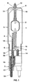
- Figure 1 shows a metal halide lamp, partly in section
- FIG. 1 shows the structure of a socket on one side according to the invention High pressure discharge lamp shown.
- High-pressure discharge lamp is a metal halide lamp for photo-optical Purposes with a power consumption of 6 kW.
- the high-pressure discharge lamp has a discharge vessel that is closed on both sides 1 made of quartz glass, in which an ionizable filling gas and two electrodes 2 are enclosed are.
- the discharge vessel 1 is evacuated by means of a two-part frame 3, 4 (or also filled with nitrogen), outer bulb sealed on one side 5 supported.
- the outer bulb 5 is essentially axially symmetrical. Its close to the base End 6 is cemented in a ceramic base 7.
- the base 7 has one High voltage strength of more than 70 kV.
- a long frame bracket 3 runs along the discharge vessel 1 to the base, dome-shaped end 8 of the outer bulb and is there with a power supply 9, which is led axially out of the discharge vessel by means of two turns 10 connected. In the area of the turns, the power supply and the bracket are included Nickel solder 11 soldered. This power supply 9 remote from the base is in a pump connection 12 fixed in the dome 8 of the outer bulb.
- the long bracket 3 is partially from a quartz glass tube 13 encased in an extension tube 20 near the base End 6 of the outer bulb 5 is inserted.
- a short frame bracket 4, which is parallel to the long bracket, is similar 3 is arranged, surrounded by a quartz glass tube 14 and in the end near the base 6 supported.
- the bracket 4 is with the end 6 near the base of the discharge vessel led out power supply 15 connected by the wire here of the bracket 4 is wound around the power supply 15.
- Nickel solder 16 soldered in the area of the connection point.
- the brackets 3, 4 made of molybdenum are each with solid strands 17 with contact pins 18 connected at the end of the base.
- the cavities inside the base are covered with a high-voltage resistant ceramic potting compound 19 filled.
- This lamp achieved in comparison to an identical lamp with spot welding as a connection between power supply and frame bracket more than 300% longer lifespan. Instead of 150 hours, more than 600 hours are achieved.
Landscapes
- Vessels And Coating Films For Discharge Lamps (AREA)
Abstract
Description
Claims (9)
- Hochdruckentladungslampe mit elektrischen Leitungen und mit einem Außenkolben (5), in dem ein Entladungsgefäß (1) mittels Gestellteilen (3,4) gehaltert ist, wobei an den Enden des Entladungsgefäßes Stromzuführungen (9,15) herausgeführt sind, dadurch gekennzeichnet, daß eine Verbindung zwischen zwei Leitungen, im folgenden als erste und zweite elektrisch leitende Zuführung bezeichnet, durch eine Lötverbindung (11;16), die Nickel und/oder Zirkon als Lot verwendet, hergestellt ist.
- Hochdruckentladungslampe nach Anspruch 1, dadurch gekennzeichnet, daß die erste Zuführung ein Gestellteil (3;4) und die zweite Zuführung eine Stromzuführung (9;15) ist.
- Hochdruckentladungslampe nach Anspruch 1, dadurch gekennzeichnet, daß die Zuführungen (3;4;9;15) Drähte mit einem Durchmesser bis 7 mm sind.
- Hochdruckentladungslampe nach Anspruch 1, dadurch gekennzeichnet, daß mindestens eine, bevorzugt beide Zuführungen aus Molybdän gefertigt sind.
- Hochdruckentladungslampe nach Anspruch 1, dadurch gekennzeichnet, daß der Betriebsstrom der Lampe mehr als 20 A beträgt.
- Hochdruckentladungslampe nach Anspruch 1, dadurch gekennzeichnet, daß die Lampe ein zweiseitig verschlossenes Entladungsgefäß (1) in einem einseitig verschlossenen Außenkolben (5) enthält.
- Hochdruckentladungslampe nach Anspruch 1, dadurch gekennzeichnet, daß eine großflächige Verbindung zwischen den beiden zu verbindenden Teilen hergestellt wird.
- Hochdruckentladungslampe nach Anspruch 7, dadurch gekennzeichnet, daß die eine der beiden Zuführungen (3;4) um die andere Zuführung (9;15) herumgewickelt ist.
- Hochdruckentladungslampe nach Anspruch 1, dadurch gekennzeichnet, daß die Lötverbindung mittels Induktion hergestellt ist.
Applications Claiming Priority (2)
| Application Number | Priority Date | Filing Date | Title |
|---|---|---|---|
| DE1999113297 DE19913297C1 (de) | 1999-03-24 | 1999-03-24 | Hochdruckentladungslampe |
| DE19913297 | 1999-03-24 |
Publications (1)
| Publication Number | Publication Date |
|---|---|
| EP1039505A1 true EP1039505A1 (de) | 2000-09-27 |
Family
ID=7902220
Family Applications (1)
| Application Number | Title | Priority Date | Filing Date |
|---|---|---|---|
| EP00103111A Withdrawn EP1039505A1 (de) | 1999-03-24 | 2000-02-16 | Hochdruckentladungslampe |
Country Status (7)
| Country | Link |
|---|---|
| EP (1) | EP1039505A1 (de) |
| JP (1) | JP2000277055A (de) |
| CN (1) | CN1269596A (de) |
| BR (1) | BR0001406A (de) |
| CA (1) | CA2300741A1 (de) |
| DE (1) | DE19913297C1 (de) |
| TW (1) | TW446989B (de) |
Families Citing this family (2)
| Publication number | Priority date | Publication date | Assignee | Title |
|---|---|---|---|---|
| DE102007015483A1 (de) | 2007-03-30 | 2008-10-02 | Osram Gesellschaft mit beschränkter Haftung | Baueinheit für eine elektrische Lampe mit Außenkolben |
| DE102010002397A1 (de) | 2010-02-26 | 2011-09-01 | Osram Gesellschaft mit beschränkter Haftung | Hochdruckentladungslampe |
Citations (5)
| Publication number | Priority date | Publication date | Assignee | Title |
|---|---|---|---|---|
| US3751577A (en) * | 1972-06-12 | 1973-08-07 | Us Army | Seal for a high pressure, short arc gas lamp |
| US4987341A (en) * | 1987-01-23 | 1991-01-22 | Heimann Gmbh | Flash lamp with metal coating on an outer end of an electrode thereof |
| EP0566975A1 (de) * | 1992-04-23 | 1993-10-27 | Patent-Treuhand-Gesellschaft für elektrische Glühlampen mbH | Einseitig gesockelte Hochdruckentladungslampe |
| US5654606A (en) * | 1994-11-08 | 1997-08-05 | U.S. Philips Corporation | Low-pressure discharge lamp having metal and ceramic electrodes |
| US5821681A (en) * | 1995-09-29 | 1998-10-13 | Wedgewood Technology, Inc. | Low pressure discharge lamp assembly |
-
1999
- 1999-03-24 DE DE1999113297 patent/DE19913297C1/de not_active Expired - Fee Related
-
2000
- 2000-02-16 EP EP00103111A patent/EP1039505A1/de not_active Withdrawn
- 2000-03-15 CA CA 2300741 patent/CA2300741A1/en not_active Abandoned
- 2000-03-15 TW TW89104752A patent/TW446989B/zh not_active IP Right Cessation
- 2000-03-21 JP JP2000078477A patent/JP2000277055A/ja active Pending
- 2000-03-23 BR BR0001406A patent/BR0001406A/pt not_active Application Discontinuation
- 2000-03-24 CN CN 00104821 patent/CN1269596A/zh active Pending
Patent Citations (5)
| Publication number | Priority date | Publication date | Assignee | Title |
|---|---|---|---|---|
| US3751577A (en) * | 1972-06-12 | 1973-08-07 | Us Army | Seal for a high pressure, short arc gas lamp |
| US4987341A (en) * | 1987-01-23 | 1991-01-22 | Heimann Gmbh | Flash lamp with metal coating on an outer end of an electrode thereof |
| EP0566975A1 (de) * | 1992-04-23 | 1993-10-27 | Patent-Treuhand-Gesellschaft für elektrische Glühlampen mbH | Einseitig gesockelte Hochdruckentladungslampe |
| US5654606A (en) * | 1994-11-08 | 1997-08-05 | U.S. Philips Corporation | Low-pressure discharge lamp having metal and ceramic electrodes |
| US5821681A (en) * | 1995-09-29 | 1998-10-13 | Wedgewood Technology, Inc. | Low pressure discharge lamp assembly |
Also Published As
| Publication number | Publication date |
|---|---|
| BR0001406A (pt) | 2000-10-17 |
| DE19913297C1 (de) | 2000-04-20 |
| CN1269596A (zh) | 2000-10-11 |
| TW446989B (en) | 2001-07-21 |
| CA2300741A1 (en) | 2000-09-24 |
| JP2000277055A (ja) | 2000-10-06 |
Similar Documents
| Publication | Publication Date | Title |
|---|---|---|
| EP0602529B1 (de) | Hochdruckentladungslampe mit einem keramischen Entladungsgefäss | |
| DE69403176T2 (de) | Elektrische Lampe | |
| DE69405181T2 (de) | Hochdruck-Entladungslampe | |
| DE3739008A1 (de) | Hochdruckentladungslampe | |
| DE69301872T2 (de) | Gesockelte elektrische Lampe | |
| DE69404926T2 (de) | Hochdruck-Entladungslampe | |
| EP0566975B1 (de) | Einseitig gesockelte Hochdruckentladungslampe | |
| DE69401445T2 (de) | Doppelgasentladungslampe mit vereinfachtem Lampenrahmen | |
| DE2358188A1 (de) | Hochleistungslampe mit einem sockel zur bogenloeschung | |
| EP0034113A1 (de) | Elektrische Entladungslampe | |
| DE19913297C1 (de) | Hochdruckentladungslampe | |
| EP1138057A1 (de) | Hochdruckentladungslampe | |
| DE69016942T2 (de) | Verbesserte Aufbauzuordnung für Doppelendlampe. | |
| EP0321867B1 (de) | Hochdruckentladungslampe | |
| DE69020465T2 (de) | Einseitig gequetschte elektrische Metalldampfentladungslampe. | |
| EP0588201B1 (de) | Hochdruckentladungslampe und Herstellungsverfahren für eine Hochdruckentladungslampe | |
| DE2611634C2 (de) | Elektrische Lampe | |
| DE69016468T2 (de) | Natriumdampflampe für Schallpulsebetrieb. | |
| EP1351278B1 (de) | Metallhalogenidlampe mit keramischem Entladungsgefäss | |
| DE69408787T2 (de) | Entladungslampe mit einem bimetallischen Schalter versehen und zu einer Lampe passender bimetallischen Schalter | |
| DE68913229T2 (de) | Metalldampfentladungslampe. | |
| DE1067930B (de) | ||
| WO2007000141A1 (de) | Elektrodensystem für eine lampe | |
| DE2535031C3 (de) | Zündelektrode für Hochdruck-Entladungslampen | |
| DE4202971A1 (de) | Hochdruckgasentladungslampe fuer gleichstrombetrieb |
Legal Events
| Date | Code | Title | Description |
|---|---|---|---|
| PUAI | Public reference made under article 153(3) epc to a published international application that has entered the european phase |
Free format text: ORIGINAL CODE: 0009012 |
|
| AK | Designated contracting states |
Kind code of ref document: A1 Designated state(s): AT BE CH CY DE DK ES FI FR GB GR IE IT LI LU MC NL PT SE |
|
| AX | Request for extension of the european patent |
Free format text: AL;LT;LV;MK;RO;SI |
|
| 17P | Request for examination filed |
Effective date: 20001106 |
|
| AKX | Designation fees paid |
Free format text: AT BE CH CY DE DK ES FI FR GB GR IE IT LI LU MC NL PT SE |
|
| GRAP | Despatch of communication of intention to grant a patent |
Free format text: ORIGINAL CODE: EPIDOSNIGR1 |
|
| STAA | Information on the status of an ep patent application or granted ep patent |
Free format text: STATUS: THE APPLICATION IS DEEMED TO BE WITHDRAWN |
|
| 18D | Application deemed to be withdrawn |
Effective date: 20030902 |