EP1039021A1 - Verfahren zum Nasssieben von Faserstoffsuspensionen in Drucksortierern und Drucksortierersieb - Google Patents
Verfahren zum Nasssieben von Faserstoffsuspensionen in Drucksortierern und Drucksortierersieb Download PDFInfo
- Publication number
- EP1039021A1 EP1039021A1 EP00103284A EP00103284A EP1039021A1 EP 1039021 A1 EP1039021 A1 EP 1039021A1 EP 00103284 A EP00103284 A EP 00103284A EP 00103284 A EP00103284 A EP 00103284A EP 1039021 A1 EP1039021 A1 EP 1039021A1
- Authority
- EP
- European Patent Office
- Prior art keywords
- sieve
- sorting
- pressure sorter
- screen according
- pressure
- Prior art date
- Legal status (The legal status is an assumption and is not a legal conclusion. Google has not performed a legal analysis and makes no representation as to the accuracy of the status listed.)
- Granted
Links
- 239000000725 suspension Substances 0.000 title claims abstract description 27
- 238000000034 method Methods 0.000 title claims description 12
- 238000012216 screening Methods 0.000 title claims description 9
- 239000000835 fiber Substances 0.000 claims abstract description 19
- 125000006850 spacer group Chemical group 0.000 claims abstract description 5
- 238000011010 flushing procedure Methods 0.000 claims abstract description 4
- 230000003014 reinforcing effect Effects 0.000 claims description 12
- 230000008569 process Effects 0.000 claims description 4
- 230000002787 reinforcement Effects 0.000 abstract 4
- 230000001788 irregular Effects 0.000 abstract 1
- 230000000694 effects Effects 0.000 description 5
- 230000004888 barrier function Effects 0.000 description 3
- 239000000356 contaminant Substances 0.000 description 3
- 238000004519 manufacturing process Methods 0.000 description 3
- 230000035508 accumulation Effects 0.000 description 2
- 238000009825 accumulation Methods 0.000 description 2
- 230000008901 benefit Effects 0.000 description 2
- 238000005516 engineering process Methods 0.000 description 2
- 239000002245 particle Substances 0.000 description 2
- 239000007787 solid Substances 0.000 description 2
- 238000011144 upstream manufacturing Methods 0.000 description 2
- 229910000851 Alloy steel Inorganic materials 0.000 description 1
- 229910000831 Steel Inorganic materials 0.000 description 1
- 230000008859 change Effects 0.000 description 1
- 238000004140 cleaning Methods 0.000 description 1
- 238000004090 dissolution Methods 0.000 description 1
- 230000029142 excretion Effects 0.000 description 1
- 230000002349 favourable effect Effects 0.000 description 1
- 238000005194 fractionation Methods 0.000 description 1
- 239000012528 membrane Substances 0.000 description 1
- 230000004048 modification Effects 0.000 description 1
- 238000012986 modification Methods 0.000 description 1
- 238000005457 optimization Methods 0.000 description 1
- 230000000717 retained effect Effects 0.000 description 1
- 238000000926 separation method Methods 0.000 description 1
- 239000010959 steel Substances 0.000 description 1
Images


Classifications
-
- D—TEXTILES; PAPER
- D21—PAPER-MAKING; PRODUCTION OF CELLULOSE
- D21D—TREATMENT OF THE MATERIALS BEFORE PASSING TO THE PAPER-MAKING MACHINE
- D21D5/00—Purification of the pulp suspension by mechanical means; Apparatus therefor
- D21D5/02—Straining or screening the pulp
- D21D5/16—Cylinders and plates for screens
Definitions
- the invention relates to a method according to the preamble of claims 1 and 2 and on a pressure sorter screen according to the preamble of claim 5.
- Strainers or strainer baskets are known from published patent application DE 33 27 422 A1, at which the sorting slots by essentially parallel, similar profiles that with transverse retaining ribs are connected, are formed.
- the profiles are like this designed and arranged so that the flow during operation of the screening device Surfaces of the profiles have an oblique contour and a tear-off edge behind them. This causes a deflection on the flowing suspension flow, which derives the suspension flow from the sorting slot so that eddies train which the clearing of the sorting slots and the sieve passage of the fibers favor.
- the invention is based on the object of a method or a screening device to create specified type, with which a better sieve clearance succeeds, at at the same time good cleaning effect and high sieve throughput.
- Slit-shaped sieve openings are particularly suitable for the process. With these is a possible advantage of the method can be achieved particularly effectively. Because it was found that the long fiber content in the sieve pass (accept) compared to conventional sieves is increased. Thus, a special problem of Slot sorting, namely the long fiber loss, easier to solve. But there are also other shapes, e.g. Round bores with deflection elements, one Can reverse vertebrae, conceivable.
- Cylindrical sieves of the type considered here are either centrifugal or flows through the centripetal region.
- the sieve has sorting slots 3 'formed between parallel bars 2' become.
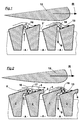
- the flow lines are in two different flow situations represented by freehand arrows.
- the sorting slot shown on the right is used by the Suspension from the inlet side of the sieve opening to the outlet side in the Flows through slot flow direction S.
- the sieve does the real thing, namely part of the suspension, which is fine enough is to be able to pass through the sorting slots 3 ', while in pass A another part is retained as an overflow. This is due to the Direction of flow and the profile shape of the sorting rods, right-handed demolition vortices 16 out.
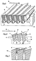
- FIG. 3 shows the part as an example of a pressure sorter screen according to the invention of such a sieve a little more detailed on average.
- This is again here around a bar screen, in which the sorting slots 3 are formed between bars 2, which in a reinforcing element 1 are used.
- the profile of the bars is simplified drawn, e.g. without the usual rounding off.
- the accepted part of the suspension as a sieve pass through the sorting 3 in the Slot flow direction S, in the example shown here from top to bottom.
- the screen surfaces 5 and 5 ' are the fictitious connecting surfaces of the rods 2 on the Inlet and outlet side of the sieve.
- the bars 2 have end faces on the inlet side 4 and end faces 4 'on the outlet side.
- the end faces 4 of the inlet side are with a front end 7 and a rear end 8 limited. After this Pass the inlet-side end face 4 in the inflow direction R, that is to say on its rear end 8, the suspension forms a vortex with an axis that is approximately in Longitudinal direction of the sorting slots 3 is. As a result, the clearance effect in Operation of the pressure sorter improved.
- the end faces 4 are at their rear end 8 Extensions 6 provided. These are designed in such a way that they are not just the only Sort slot 3, but also the front end 7 of the the sorting slot 3 following rod 2.
- the extension 6 has an underside 9 facing the front end 7 of the adjacent rod on. This underside 9 and the front end 7 of the end face 4 are in an angle ⁇ to each other, which is between 3 and 45 °, preferably between 8 ° and 25 °.
- the choice of the angle ⁇ also ensures that the flow cross-section, seen in the direction of the upstream, expanded. That is, in the In the opposite direction, i.e. the direction of the backflow, the suspension is accelerated, which is favorable for the dissolution and flushing of accumulations.
- the extensions 6 can e.g. by subsequent plastic deformation are formed so that they also the Cover sorting slot 3 and the adjacent area of the sieve body.
- the slot width w which is decisive for the sieve characteristic, is formed as on the second and third sorting rod shown, between the bottom 9 of the extension 6 and End face 4 of the adjacent rod.
- the end faces 4 are in here Flow direction R increases with an angle of inclination ⁇ relative to the screen surface 5 inclined, causing the inflowing suspension against the slot flow direction S is distracted.
- Flow direction R increases with an angle of inclination ⁇ relative to the screen surface 5 inclined, causing the inflowing suspension against the slot flow direction S is distracted.
- a difference h measured perpendicular to the screen surface 5 to the end face 4 of the adjacent rod. That formed by this difference h Volume promotes the desired vortex.
- the extensions 6 run evenly over the entire length of the rods, so that the flow conditions are the same everywhere. But it is also conceivable instead of a continuous extension, a large number of small extensions to attach, e.g. to create advantageous cross vortex. One more way is to make the overhang of the extensions different. Because in operation the pressure sorter along the rods different solids - in particular Contaminant concentrations occur, offers a change in the shape or size of the Extensions an additional optimization possibility.
- FIG. 4 can be cylindrical Strainer basket designed by a plurality of annular reinforcing elements 1 is held together.
- the illustration shows only a part of the existing bars 2 and without the extensions being recognizable.
- the part of a pressure sorter screen according to the invention is in perspective shown.
- the profile of the rods points in the reinforcing elements 1 used thickened side. This particular shape depends on the manufacture together.
- the depressions 10 in the reinforcing elements 1 are Insert the bars 2 'so that they can be easily inserted. A subsequent plastic deformation of the reinforcing elements 1 the depressions narrowed and the rods clamped. The finished sieve is then with properly fixed rods.
- the spacer lugs can be far apart, e.g. approx. 200 mm. In cases where, for reasons of screening technology, relatively short Slots, e.g. 0.5 to 2 mm, if desired, this solution also offers correspondingly many spacers.
- Fig. 7 shows an embodiment in which the pressure sorter screen 14 with round Screen openings 15 is provided. The direction of rotation of the vortex is reversed by the extensions 6 '.
- Fig. 8 the geometric conditions on the inflow side of the screen are somewhat presented in more detail. Similar to Fig. 6, the bottom 9 is here again Provide extensions 6 with an inclination angle ⁇ relative to the screen surface 5, So not parallel to it, with the inclination between 2 ° and 40 °. Also the The end face 4 itself is inclined with respect to the sieve face 5. This angle of inclination ⁇ should be between 5 and 50 °. An obliquely directed channel is thus formed an inclined end face 4, which also the desired flushing of the end faces unfavorable conditions guaranteed.
Landscapes
- Engineering & Computer Science (AREA)
- Mechanical Engineering (AREA)
- Paper (AREA)
- Combined Means For Separation Of Solids (AREA)
Abstract
Description
- Fig. 1
- Strömungsverhältnisse am Einlauf des Drucksortierersiebes gemäß dem Stand der Technik;
- Fig. 2
- Strömungsverhältnisse bei der Durchführung des erfindungsgemäßen Verfahrens;
- Fig. 3
- Teil eines erfindungsgemäßen Drucksortierersiebes im Schnitt;
- Fig. 4
- einen zylindrischen Siebkorb;
- Fig. 5
- Variante, perspektivisch gezeichnet;
- Fig. 6
- eine weitere Variante im Schnitt;
- Fig. 7
- eine Variante mit runden Sieböffnungen;
- Fig. 8
- Details des Einlaufbereiches;
- Fig. 9
- eine Variation der Strömungsverhältnisse.
Claims (21)
- Verfahren zum Nasssieben von Faserstoffsuspensionen in einem Drucksortierer,dadurch gekennzeichnet,bei dem diese entlang einem mit Sieböffnungen versehenen Sieb geführt wird, wodurch an der Einströmseite in das Sieb Abrisswirbel (16) entstehen,bei dem durch die Sieböffnungen ein Teil der Faserstoffsuspension als Durchlauf (A) hindurchtritt und der andere Teil als Überlauf abgewiesen wird, undbei dem mit Hilfe von relativ zum Sieb bewegten Räumern (12) Druck- oder Saugstöße an den Sieböffnungen derart erzeugt werden, dass darin Vor- und Rückströmungen entstehen,dass die Einströmseite des Siebes so gestaltet ist, dass durch die Rückströmung die Strömungsrichtung des Abrisswirbels (16) umgekehrt wird,
wobei die Rückströmung den Teil des Siebes spült, der zwischen der betreffenden Sieböffnung und der stromabwärtig folgenden liegt. - Verfahren zum Nasssieben von Faserstoffsuspensionen in einem Drucksortierer,dadurch gekennzeichnet,bei dem diese entlang einem mit Sieböffnungen versehenen Sieb geführt wird, wodurch an der Einströmseite in das Sieb Abrisswirbel (16) entstehen,bei dem durch die Sieböffnungen ein Teil der Faserstoffsuspension als Durchlauf (A) hindurchtritt und der andere Teil als Überlauf abgewiesen wird, undbei dem mit Hilfe von relativ zum Sieb bewegten Räumern (12) Druck- oder Saugstöße an den Sieböffnungen derart erzeugt werden, dass darin Vor- und Rückströmungen entstehen,dass die Rückströmung beim Austritt aus der Sieböffnung so umgelenkt wird, dass ihre Strömungsrichtung umgekehrt verläuft wie die Umfangsströmung des Abrisswirbels (16), und dass die Rückströmung den Teil des Siebes vollständig spült, der zwischen der betreffenden Sieböffnung und der stromabwärts folgenden Sieböffnung liegt.
- Verfahren nach Anspruch 1 oder 2,
dadurch gekennzeichnet,dass die Sieböffnungen als Sortierschlitze (3) ausgebildet sind, deren Längserstreckung sich im wesentlichen quer zur Bewegungsrichtung (R) des Räumers (12) erstreckt und dass die Achse der erzeugten Abrisswirbel etwa parallel zu den Sortierschlitzen (3) verläuft. - Verfahren nach Anspruch 1, 2 oder 3,
dadurch gekennzeichnet,dass die Spülung des Siebes auf der dem Räumer (12) zugewandten Seite des Siebes erfolgt. - Drucksortierersieb zum Nasssieben von Faserstoffsuspensionen mit einer Vielzahl von im wesentlichen parallel ausgerichteten Sortierschlitzen (3), durch die der beim Nasssieben akzeptierte Teil der Faserstoffsuspension hindurchtritt, welches zwischen den Sortierschlitzen (3) Stirnflächen (4, 4') aufweist mit jeweils einem vorderen Abschluss (7) und einem hinteren Abschluss (8),
dadurch gekennzeichnet,dass die Stirnflächen (4, 4') am hinteren Abschluss (8) mit Verlängerungen (6) versehen sind,welche jeweils einen benachbarten Sortierschlitz (3) und darüber hinaus einen Teil des vorderen Abschlusses (7) der diesem Sortierschlitz (3) benachbarten Stirnfläche (4) auf eine Länge (b) von mindestens 0,5 mm abdecken,
wobei die Stirnfläche (4) am vorderen Abschluss (7) und die diesem zugewandte Unterseite (9) der Verlängerung (6) in einem Winkel (α) zwischen 3° und 45°, vorzugsweise 5° bis 25° zueinanderstehen. - Drucksortierersieb nach Anspruch 5,
dadurch gekennzeichnet,dass die Länge (b) mindestens 1 mm beträgt. - Drucksortierersieb nach Anspruch 5 oder 6,
dadurch gekennzeichnet,dass die Verlängerungen (6) an den zulaufseitigen Stirnflächen (4) liegen, an denen bei Betrieb des Drucksortierers die Suspension in den Sortierschlitz einströmt. - Drucksortierersieb nach Anspruch 5, 6 oder 7,
dadurch gekennzeichnet,dass der hintere Abschluss (8) an der Seite der Stirnfläche (4) liegt, die bei Betrieb des Drucksortierers bezüglich der Anströmung (R) der Faserstoffsuspension an das Sieb stromabwärts liegt. - Drucksortierersieb nach Anspruch 5, 6, 7 oder 8,
dadurch gekennzeichnet,dass die Stirnflächen (4) gegen die Siebfläche (5) mit einem Neigungswinkel (β) zwischen 5° und 50°, vorzugsweise 10° bis 30°, geneigt sind. - Drucksortierersieb nach einem der Ansprüche 5 bis 9,
dadurch gekennzeichnet,dass die Stirnfläche (4) frei ist von Kanten, durch die sich im Betrieb zusätzliche Staupunkte bilden würden. - Drucksortierersieb nach einem der Ansprüche 5 bis 10,
dadurch gekennzeichnet,dass die zur Sieböffnung weisende Unterseite (9) der Verlängerung (6) zur Siebfläche (5) einen Neigungswinkel (γ) zwischen 2°, bis 40°, vorzugsweise 5° bis 25° aufweist. - Drucksortierersieb nach einem der Ansprüche 5 bis 11,
dadurch gekennzeichnet,dass Sortierschlitze (3) zwischen Stäben (2, 2', 2'') gebildet weden, die aus Profilen bestehen und in Verstärkungselementen (1) fixiert sind, wobei die Verstärkungselemente (1) Vertiefungen (10) zur Aufnahme der Stäbe (2, 2', 2'') aufweisen und mehrere oder alle an dem Sieb vorhandenen Stäbe (2, 2', 2'') verbinden. - Drucksortierersieb nach Anspruch 12,
dadurch gekennzeichnet,dass die Stäbe (2, 2', 2'') in den Verstärkungselementen (1) durch Spannungen infolge von plastischer Verformung der Verstärkungselemente (1) fixiert sind. - Drucksortierersieb nach Anspruch 12 oder 13,
dadurch gekennzeichnet,dass die Unterseiten (9) der Verlängerungen (6) mehrere über die Längserstreckung der Stäbe (2'') verteilte Distanznasen (11) aufweisen, die sich auf die jeweils benachbarten Stirnflächen (4) abstützen. - Drucksortierersieb nach Anspruch 12, 13 oder 14,
dadurch gekennzeichnet,dass die Verstärkungselemente (1) als Ringe ausgebildet sind, so dass das Sieb ein zylindrischer Siebkorb ist. - Drucksortierersieb nach Anspruch 15,
dadurch gekennzeichnet,dass Verstärkungselemente (1) und Stäbe (2, 2', 2'') in zueinander parallelen Ebenen angeordnet sind, so dass das Sieb ein Plansieb ist. - Drucksortierersieb nach einem der Ansprüche 5 bis 16,
dadurch gekennzeichnet,dass die Siebweite (w) zwischen 0,08 und 2 mm beträgt. - Drucksortierersieb nach einem der Ansprüche 5 bis 17,
dadurch gekennzeichnet,dass sich die Verlängerungen (6) im wesentlichen über die ganze Länge der Sortierschlitze (3) erstrecken. - Drucksortierersieb nach einem der Ansprüche 5 bis 17,
dadurch gekennzeichnet,dass die Verlängerungen (6) in Längsrichtung der Sortierschlitze (3) vielfach unterteilt sind. - Drucksortierersieb nach einem der Ansprüche 5 bis 19,
dadurch gekennzeichnet,dass die Form der Verlängerungen (6) längs der Sortierschlitze (3) uneinheitlich ist. - Drucksortierersieb nach einem der Ansprüche 5 bis 20,
dadurch gekennzeichnet,dass die Länge der Sortierschlitze (3) nicht größer als 10 mm ist.
Applications Claiming Priority (4)
| Application Number | Priority Date | Filing Date | Title |
|---|---|---|---|
| DE19913515 | 1999-03-25 | ||
| DE19913515 | 1999-03-25 | ||
| DE19916038A DE19916038A1 (de) | 1999-03-25 | 1999-04-09 | Verfahren zum Nasssieben von Faserstoffsuspensionen in Drucksortierern und Drucksortierersieb |
| DE19916038 | 1999-04-09 |
Publications (2)
| Publication Number | Publication Date |
|---|---|
| EP1039021A1 true EP1039021A1 (de) | 2000-09-27 |
| EP1039021B1 EP1039021B1 (de) | 2004-04-21 |
Family
ID=26052582
Family Applications (1)
| Application Number | Title | Priority Date | Filing Date |
|---|---|---|---|
| EP00103284A Expired - Lifetime EP1039021B1 (de) | 1999-03-25 | 2000-02-18 | Verfahren zum Nasssieben von Faserstoffsuspensionen in Drucksortierern und Drucksortierersieb |
Country Status (3)
| Country | Link |
|---|---|
| US (1) | US6273266B1 (de) |
| EP (1) | EP1039021B1 (de) |
| AT (1) | ATE264940T1 (de) |
Families Citing this family (5)
| Publication number | Priority date | Publication date | Assignee | Title |
|---|---|---|---|---|
| JP4376151B2 (ja) * | 2004-08-09 | 2009-12-02 | 相川鉄工株式会社 | スクリーン装置 |
| FI122697B (fi) * | 2005-11-02 | 2012-05-31 | Metso Paper Inc | Sihtisylinteri |
| TW200736458A (en) * | 2006-03-24 | 2007-10-01 | Slit And Hole Industry Co Ltd | A sieve (screen) can prevent sieve bars from falling off |
| CN116046154B (zh) * | 2022-12-21 | 2026-02-10 | 自然资源部第一海洋研究所 | 一种漂浮式海洋噪声监测设备 |
| CN120346975B (zh) * | 2025-05-28 | 2025-12-30 | 青岛农业大学 | 一种药物多级筛选方法及设备 |
Citations (2)
| Publication number | Priority date | Publication date | Assignee | Title |
|---|---|---|---|---|
| EP0286535A1 (de) * | 1987-04-06 | 1988-10-12 | E. et M. LAMORT | Siebe für Papierstoffreiniger |
| EP0499154A1 (de) * | 1991-02-15 | 1992-08-19 | J.M. Voith GmbH | Siebkorb |
Family Cites Families (2)
| Publication number | Priority date | Publication date | Assignee | Title |
|---|---|---|---|---|
| DE3327422C2 (de) | 1983-07-29 | 1995-03-16 | Voith Gmbh J M | Sieb, insbesondere für die Sortierung von auf der Grundlage von Altpapier hergestellten Fasersuspensionen |
| DE4435538C2 (de) | 1994-10-05 | 1996-10-02 | Voith Gmbh J M | Verfahren zur Herstellung eines Flachsiebes |
-
2000
- 2000-02-18 AT AT00103284T patent/ATE264940T1/de active
- 2000-02-18 EP EP00103284A patent/EP1039021B1/de not_active Expired - Lifetime
- 2000-03-24 US US09/534,329 patent/US6273266B1/en not_active Expired - Fee Related
Patent Citations (2)
| Publication number | Priority date | Publication date | Assignee | Title |
|---|---|---|---|---|
| EP0286535A1 (de) * | 1987-04-06 | 1988-10-12 | E. et M. LAMORT | Siebe für Papierstoffreiniger |
| EP0499154A1 (de) * | 1991-02-15 | 1992-08-19 | J.M. Voith GmbH | Siebkorb |
Also Published As
| Publication number | Publication date |
|---|---|
| US6273266B1 (en) | 2001-08-14 |
| EP1039021B1 (de) | 2004-04-21 |
| ATE264940T1 (de) | 2004-05-15 |
Similar Documents
| Publication | Publication Date | Title |
|---|---|---|
| DE102007020325B3 (de) | Verfahren zur Herstellung eines Siebes für die Behandlung von zur Papiererzeugung geeigneten Faserstoffsuspensionen | |
| DE69311898T3 (de) | Vorrichtung zur behandlung von fasersuspensionen | |
| DE3327422A1 (de) | Sieb, insbesondere fuer die sortierung von auf der grundlage von altpapier hergestellten fasersuspensionen | |
| DE1761600B2 (de) | Vorrichtung zum sichten von faserstoffaufschwemmungen | |
| DE1761930A1 (de) | Sichter von Faserstoffausschwemmungen,insbesondere von Zellstoff fuer Papier | |
| DE4214061C2 (de) | Siebvorrichtung | |
| EP1039021B1 (de) | Verfahren zum Nasssieben von Faserstoffsuspensionen in Drucksortierern und Drucksortierersieb | |
| EP1357222B1 (de) | Verfahren zum Nasssieben von Faserstoffsuspensionen | |
| DE69808945T2 (de) | Rakelanordnung für eine fasersiebvorrichtung | |
| DE102004047948B4 (de) | Sortierer | |
| EP2780505B1 (de) | Sieb | |
| DE19916038A1 (de) | Verfahren zum Nasssieben von Faserstoffsuspensionen in Drucksortierern und Drucksortierersieb | |
| DE19625726C1 (de) | Siebvorrichtung mit spaltförmigen Öffnungen | |
| DE19609316C2 (de) | Verfahren zur Herstellung einer Siebvorrichtung mit kontrolliert ungleichmäßigen Sortierschlitzen sowie Siebvorrichtung und deren Verwendung | |
| DE10065930B4 (de) | Verfahren zur Herstellung von Sieben, die zur Nasssiebung von Papierfasersuspensionen verwendbar sind | |
| DE4107905C2 (de) | Herstellverfahren zum Herstellen eines geschlitzten Siebkorbes | |
| DE10045454A1 (de) | Siebvorrichtung zum Nasssieben von Faserstoffsuspensionen in Drucksortierern | |
| DE20304303U1 (de) | Drucksortierer zum Sieben einer Papierfaserstoffsuspension und Siebräumer für einen solchen | |
| DE19747653C2 (de) | Sieb für Faserstoffsuspensionen | |
| DE202007014091U1 (de) | Sieb, insbesondere starres Sieb für die Behandlung von zur Papiererzeugung geeigneten Faserstoffsuspensionen | |
| DE10112478A1 (de) | Verfahren zum Sortieren einer Faserstoffsuspension | |
| DE212007000035U1 (de) | Siebflügel und Sieb zum Sieben von Stoff | |
| DE19736127A1 (de) | Verfahren und Siebvorrichtung zum Sortieren von nassen schmutzstoffhaltigen Faserstoffen | |
| DE102024108109A1 (de) | Profilstab für einen Siebkorb für die Faseraufbereitung | |
| DE19951711A1 (de) | Verfahren und Vorrichtung zum Fraktionieren einer papierfaserhaltigen Suspension |
Legal Events
| Date | Code | Title | Description |
|---|---|---|---|
| PUAI | Public reference made under article 153(3) epc to a published international application that has entered the european phase |
Free format text: ORIGINAL CODE: 0009012 |
|
| AK | Designated contracting states |
Kind code of ref document: A1 Designated state(s): AT DE FI FR IT SE |
|
| AX | Request for extension of the european patent |
Free format text: AL;LT;LV;MK;RO;SI |
|
| RAP1 | Party data changed (applicant data changed or rights of an application transferred) |
Owner name: VOITH PAPER PATENT GMBH |
|
| 17P | Request for examination filed |
Effective date: 20010327 |
|
| AKX | Designation fees paid |
Free format text: AT DE FI FR IT SE |
|
| 17Q | First examination report despatched |
Effective date: 20030109 |
|
| GRAP | Despatch of communication of intention to grant a patent |
Free format text: ORIGINAL CODE: EPIDOSNIGR1 |
|
| GRAS | Grant fee paid |
Free format text: ORIGINAL CODE: EPIDOSNIGR3 |
|
| GRAA | (expected) grant |
Free format text: ORIGINAL CODE: 0009210 |
|
| AK | Designated contracting states |
Kind code of ref document: B1 Designated state(s): AT DE FI FR IT SE |
|
| REF | Corresponds to: |
Ref document number: 50006113 Country of ref document: DE Date of ref document: 20040527 Kind code of ref document: P |
|
| REG | Reference to a national code |
Ref country code: SE Ref legal event code: TRGR |
|
| ET | Fr: translation filed | ||
| PLBE | No opposition filed within time limit |
Free format text: ORIGINAL CODE: 0009261 |
|
| STAA | Information on the status of an ep patent application or granted ep patent |
Free format text: STATUS: NO OPPOSITION FILED WITHIN TIME LIMIT |
|
| 26N | No opposition filed |
Effective date: 20050124 |
|
| PGFP | Annual fee paid to national office [announced via postgrant information from national office to epo] |
Ref country code: FR Payment date: 20110302 Year of fee payment: 12 Ref country code: DE Payment date: 20110218 Year of fee payment: 12 Ref country code: SE Payment date: 20110214 Year of fee payment: 12 Ref country code: IT Payment date: 20110221 Year of fee payment: 12 |
|
| PGFP | Annual fee paid to national office [announced via postgrant information from national office to epo] |
Ref country code: FI Payment date: 20120213 Year of fee payment: 13 |
|
| PG25 | Lapsed in a contracting state [announced via postgrant information from national office to epo] |
Ref country code: SE Free format text: LAPSE BECAUSE OF NON-PAYMENT OF DUE FEES Effective date: 20120219 |
|
| REG | Reference to a national code |
Ref country code: FR Ref legal event code: ST Effective date: 20121031 |
|
| PG25 | Lapsed in a contracting state [announced via postgrant information from national office to epo] |
Ref country code: IT Free format text: LAPSE BECAUSE OF NON-PAYMENT OF DUE FEES Effective date: 20120218 |
|
| REG | Reference to a national code |
Ref country code: DE Ref legal event code: R119 Ref document number: 50006113 Country of ref document: DE Effective date: 20120901 |
|
| PG25 | Lapsed in a contracting state [announced via postgrant information from national office to epo] |
Ref country code: FR Free format text: LAPSE BECAUSE OF NON-PAYMENT OF DUE FEES Effective date: 20120229 |
|
| PGFP | Annual fee paid to national office [announced via postgrant information from national office to epo] |
Ref country code: AT Payment date: 20120213 Year of fee payment: 13 |
|
| PG25 | Lapsed in a contracting state [announced via postgrant information from national office to epo] |
Ref country code: DE Free format text: LAPSE BECAUSE OF NON-PAYMENT OF DUE FEES Effective date: 20120901 |
|
| REG | Reference to a national code |
Ref country code: AT Ref legal event code: MM01 Ref document number: 264940 Country of ref document: AT Kind code of ref document: T Effective date: 20130228 |
|
| PG25 | Lapsed in a contracting state [announced via postgrant information from national office to epo] |
Ref country code: AT Free format text: LAPSE BECAUSE OF NON-PAYMENT OF DUE FEES Effective date: 20130228 Ref country code: FI Free format text: LAPSE BECAUSE OF NON-PAYMENT OF DUE FEES Effective date: 20130218 |