EP1038757A2 - Einrichtung zur Lenkung eines Fahrzeugs und Fahrzeug - Google Patents
Einrichtung zur Lenkung eines Fahrzeugs und Fahrzeug Download PDFInfo
- Publication number
- EP1038757A2 EP1038757A2 EP00106001A EP00106001A EP1038757A2 EP 1038757 A2 EP1038757 A2 EP 1038757A2 EP 00106001 A EP00106001 A EP 00106001A EP 00106001 A EP00106001 A EP 00106001A EP 1038757 A2 EP1038757 A2 EP 1038757A2
- Authority
- EP
- European Patent Office
- Prior art keywords
- steering
- vehicle
- drive
- gears
- operator
- Prior art date
- Legal status (The legal status is an assumption and is not a legal conclusion. Google has not performed a legal analysis and makes no representation as to the accuracy of the status listed.)
- Withdrawn
Links
Images



Classifications
-
- B—PERFORMING OPERATIONS; TRANSPORTING
- B62—LAND VEHICLES FOR TRAVELLING OTHERWISE THAN ON RAILS
- B62D—MOTOR VEHICLES; TRAILERS
- B62D11/00—Steering non-deflectable wheels; Steering endless tracks or the like
- B62D11/02—Steering non-deflectable wheels; Steering endless tracks or the like by differentially driving ground-engaging elements on opposite vehicle sides
- B62D11/06—Steering non-deflectable wheels; Steering endless tracks or the like by differentially driving ground-engaging elements on opposite vehicle sides by means of a single main power source
- B62D11/10—Steering non-deflectable wheels; Steering endless tracks or the like by differentially driving ground-engaging elements on opposite vehicle sides by means of a single main power source using gearings with differential power outputs on opposite sides, e.g. twin-differential or epicyclic gears
- B62D11/14—Steering non-deflectable wheels; Steering endless tracks or the like by differentially driving ground-engaging elements on opposite vehicle sides by means of a single main power source using gearings with differential power outputs on opposite sides, e.g. twin-differential or epicyclic gears differential power outputs being effected by additional power supply to one side, e.g. power originating from secondary power source
- B62D11/18—Steering non-deflectable wheels; Steering endless tracks or the like by differentially driving ground-engaging elements on opposite vehicle sides by means of a single main power source using gearings with differential power outputs on opposite sides, e.g. twin-differential or epicyclic gears differential power outputs being effected by additional power supply to one side, e.g. power originating from secondary power source the additional power supply being supplied hydraulically
-
- B—PERFORMING OPERATIONS; TRANSPORTING
- B62—LAND VEHICLES FOR TRAVELLING OTHERWISE THAN ON RAILS
- B62D—MOTOR VEHICLES; TRAILERS
- B62D11/00—Steering non-deflectable wheels; Steering endless tracks or the like
- B62D11/02—Steering non-deflectable wheels; Steering endless tracks or the like by differentially driving ground-engaging elements on opposite vehicle sides
- B62D11/06—Steering non-deflectable wheels; Steering endless tracks or the like by differentially driving ground-engaging elements on opposite vehicle sides by means of a single main power source
- B62D11/10—Steering non-deflectable wheels; Steering endless tracks or the like by differentially driving ground-engaging elements on opposite vehicle sides by means of a single main power source using gearings with differential power outputs on opposite sides, e.g. twin-differential or epicyclic gears
- B62D11/14—Steering non-deflectable wheels; Steering endless tracks or the like by differentially driving ground-engaging elements on opposite vehicle sides by means of a single main power source using gearings with differential power outputs on opposite sides, e.g. twin-differential or epicyclic gears differential power outputs being effected by additional power supply to one side, e.g. power originating from secondary power source
- B62D11/18—Steering non-deflectable wheels; Steering endless tracks or the like by differentially driving ground-engaging elements on opposite vehicle sides by means of a single main power source using gearings with differential power outputs on opposite sides, e.g. twin-differential or epicyclic gears differential power outputs being effected by additional power supply to one side, e.g. power originating from secondary power source the additional power supply being supplied hydraulically
- B62D11/183—Control systems therefor
Definitions
- the invention relates to a device for steering a Vehicle with at least two drivable wheels, with at least a steering means and a direction selection means, and a Vehicle.
- Such types of drive and steering gears are described in the articles Tanks and dozers turn on a dime with new all-gear steering ", Popular Science, July 1985, pp. 60-62 and Tank Steering Mechanisms ", The Engineer”, March 3, 1967, pp. 337-340.
- These transmissions have a drive unit with a drive differential that receives drive energy from a vehicle power source that drives the vehicle during operation.
- the drive unit has a drive input controller that is controlled by an operator can be engaged to vary the speed and the forward and backward direction of the vehicle.
- the transmission further comprises a steering unit with a steering differential.
- the steering unit has a steering input control that can be activated by an operator to
- the steering unit engages the drive unit such that when the steering input control is engaged to perform a turn that increases the speed of the chain on one side of the vehicle and proportional to the speed of the chain on the other side of the vehicle is reduced. In this way, the vehicle turns.
- the operator can engage the steering input control, causing the chain on one side of the vehicle to drive forward and the chain on the other side of the vehicle backward at corresponding speeds.
- a transmission with a planetary gear arrangement functions in a similar manner to a drive and steering gear with differentials as described above.
- This type of transmission also has a drive unit with a drive input control and a steering unit with a steering input control.
- the steering unit interacts with the drive unit to increase the speed of the chains on one side of the vehicle and to reduce the speed of the chains on the other side of the vehicle accordingly.
- drive and steering gears allow the vehicle to be highly maneuverable and they allow the vehicle to corner Zero "radius and rotation to be performed on the spot.
- These drive and steering gears are typically provided on heavy duty vehicles such as tanks, bulldozers and other large caterpillars.
- the steering means is preferably a steering wheel, with the handling of which most Operators are familiar. But it is also the use a joystick / steering lever or other steering means, such as for example a touchpad, conceivable.
- the steering means is preferably attached to the vehicle and is by a operator sitting or standing the vehicle operated.
- the direction selection means can usually by pedals are formed that are selective for the forward or Reverse drive can be operated.
- the use of only one Pedals are conceivable, for example, they are pivoted and forward and backward Reverse direction of travel is pressed backwards.
- a selection the direction of travel can also be selected using the selector lever or Switches etc. can be made.
- the steering information, as well the output of the direction selection means can be in the form of a Movement, for example a rotary movement of a steering wheel, which via a form of gear or lever arrangement to the Means can be transferred, or one through one electrical element generated electrical signal that over Lines is transmitted, may be provided.
- the means can have a cam element, which is preferably around a shaft provided stationary on the vehicle, for example in the manner of storage on a frame of the Vehicle, is pivotable.
- a cam element can be in Dependence on the mediated by the steering means Steering information can be pivoted. In the usual way this can happen that a steering movement via a steering spindle via a pinion in a sliding movement of a steering linkage is implemented, which is then directly or indirectly on the Cam element attacks.
- the introduced steering information to a transmission device be passed on. If it is provided that the Position of the cam element and the transmission device is mutually changeable, so that by the cam element steering information passed on to the transmission device to be changed.
- the position of the cam element can for example depending on the speed of the vehicle be so that, for example, at high speed Dampening violent steering movement is possible.
- the position of the cam element but at least from the output dependent on the direction of travel so that over the Connection of the transmission device to the cam element one Inverting the steering information is possible.
- a reversal of the pivoting of the cam member Steering information introduced can, for example, thereby take place that the transmission device on the cam element is movable or generally slidably attached.
- Around limit the range of motion of the transmission device can, at least two stops are provided. Is the Rotary shaft of the cam element between the stops arranged, causes a displacement of the Transfer device from one stop to another and one Hold in that position with respect to the cam element that the direction of those passed through the cam member Steering information is reversed.
- Transmission device in the direction of a neutral position strain.
- a neutral position can consist in that the transmission device is not at one of the stops is applied and within its preferably movable Storage can move so that one through the cam member passed steering movement not to a movement or Displacement of the transmission device leads. This can be beneficial to ensure that no steering movement is passed on if no edition of the Direction selector is available for what for example, if the vehicle is stationary or none Operator has taken a seat on the vehicle.
- the position of the transmission device based on the Cam element can be pivoted by a preferably Lever element can be determined, for example the Transmission device depending on the output of the Direction selector with one of the stops to the system brings.
- a lever element one or several actuators may be provided for example, can be attached to the cam member to adjust the actuator in relation to this.
- Various shapes can be used under one actuator of actuators, for example in the manner of a solenoid with a depending on the state of excitation of the solenoid retracted or extended mandrel, or a hydraulic or pneumatic motor can be understood.
- the control can ever electrical, pneumatic or hydraulic, depending on the shape of the actuator respectively.
- the transmission device gives the steering movement to one Drive further, the one by receiving steering information Speed difference between the driven wheels generated. This is preferably done by the a drive unit generated drive speed of the wheels at a speed generated by the steering unit is superimposed.
- the drive is preferably provided as a hydrostatic drive, wherein the transmission device directly or indirectly to a pump of the drive or on a swash plate of the pump can.
- a hydrostatic drive enables stepless Transmission.
- Such a device can preferably be attached to vehicles Vehicles for lawn, garden or property maintenance be used. On such vehicles, drive and Steering gear used to get the best possible To ensure maneuverability, for example, in order to to be able to turn in the tightest of spaces or to to be able to execute small radii.
- vehicles can lawn tractors, ride-on mowers, sweepers or also deal with snow blowers or snow clearers that are also available in narrow property area or on difficult terrain must be usable. But it is also a stake such a facility on small construction machines such as Skid steer loaders or on work and Harvesters conceivable to improve their manageability.
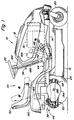
- Figure 1 shows a lawn and garden tractor or a vehicle 10 according to the present invention.
- a mower 12 On this vehicle 10 a mower 12 is attached, which is below a Vehicle frame 14 is arranged.
- a power source or a drive 16 is below a hood 18 in a front Area of the vehicle 10 is arranged and is effective with the Mower 12 connected to rotational energy in the mower 12 arranged mower blades to transmit.
- the cutting blades rotate in the mower 12 to cut grass when the vehicle 10 moved across the surface.
- the vehicle 10 has a pair front freewheels or wheels 20 and 22 on the Touch and swivel the ground when the vehicle 10 is one Turns.
- the vehicle 10 has a rear pair from the ground-contacting wheels 24 and 26, which are effective with the drive 16 are connected to the vehicle 10 via the Moving floor.
- An operator can operate a steering wheel 28 operate to cause the left and right rear wheel 24 and 26 with a different Rotate speed to cause the Vehicle 10 takes a turn as detailed below is described.
- An operator platform 30 which has a seat 32 on which an operator during a Vehicle ride sits.
- a plurality of control levers 34 are shown in FIG the operator platform 30 arranged and can by the Operator be operated to operate the vehicle 10 to control.
- the steering wheel 28 is provided, which by the operator can be operated to cause that the vehicle 10 takes a turn.
- a linkage 36 is effectively connected to the steering wheel 28, the gear 38 in following is described in more detail.
- a forward pedal 40 is provided and can be depressed by the operator to drive the vehicle 10 in the forward direction. Each further the operator presses the forward pedal 40, each vehicle 10 will move faster in forward operation.
- a reverse pedal 42 is also provided which causes that the vehicle 10 is traveling in the reverse direction when the Operator depresses the reverse pedal 42. The farther the operator presses the reverse pedal 42 the faster the vehicle 10 will move in reverse.
- On Linkage 44 which is between the pedals 40 and 42 and the Transmission 38 extends is described in more detail below separately.
- the vehicle 10 has a transmission 38, which serves a dual function regarding the transfer of rotational energy from the drive 16 to the wheels 24 and 26 to the vehicle 10 over the Moving underground, and changing the Speed of rotation of the left and right wheels 24 and 26, so that the wheels 24 and 26 with different Rotate speed to thereby turn vehicle applications execute and to be able to steer the vehicle 10.
- Two types of gears are described here, which for Use in accordance with the present invention are adapted for driving and steering the vehicle 10. On the first is here as a two-type gearbox Differentials referenced and the second is referred to taken as a planetary gear.
- the Two-differential transmission is described first.
- FIG. 2 a diagram of a Gear 46 with two differentials for use in the present invention is shown.
- the gear 46 has one Drive unit 48 and a steering unit 50, each of which have a differential 52, 54.
- the drive unit 48 receives rotational energy from the drive 16.
- a belt 56 which is effectively connected to and through the drive 16 is driven, extends backwards and attacks a drive pulley 58.
- the drive pulley 58 is with a drive input shaft 60 of a drive range a hydrostatic drive 62 connected.
- Rotational energy, which was shown by the drive 16 is the Belt system to the drive pulley 58 and in the Transfer drive area of the hydrostatic drive 62.
- the Swashplate of the drive pump 64 is controllable to the Delivery line of the pump 64 can vary, and is with a linkage 44 connected to the forward pedal 40th and the reverse pedal 42 extends.
- the operator operates the forward pedal 40 and the reverse pedal 42.
- one To pivot drive control input shaft 66 which in turn controls the delivery rate of the pump 64 and thereby the amount of rotational energy of the drive 16 increased or decreased, the transmitted to the wheels 24, 26 by the drive unit 48 becomes.
- the speed of the vehicle 10 is thereby controlled.
- Depressing the forward pedal 40 causes that the drive control input shaft 66 in a first direction which rotates the transmission 46, the wheels 24th and 26 drive in a forward direction
- a Depressing the reverse pedal 42 causes the Drive control input shaft 66 into a second opposite Pivots direction, which causes the transmission 46, the Drive wheels 24 and 26 in a reverse direction.
- the Linkage 44 which is between the pedals 40, 42 and Drive control input shaft 66 extends below described.
- the motor 68 of the drive unit 48 has one Output shaft 70 with a gear 72.
- the gear 72 drives a series of gears 74, which in turn Ring gear 76 of the differential 52 of the drive unit 48 drive.
- the differential 52 has a housing 78, Planet gears 80 and a pair of side gears 82, which on respective left and right drive shafts 84, 86 are arranged, which extends from the housing 78 to the outside extend. With the left and right drive shafts 84, 86 Left and right first gears 88, 90 are connected, respectively.
- the steering wheel 28 has a linkage 36 that is extends backward to on a steering control input shaft 92 of a steering area of the hydrostatic drive 94 to attack and control them.
- the steering linkage 36 is described in more detail below.
- the steering pump 96 receives Rotational energy from the drive 16 via the belt system.
- a Steering unit pulley 98 engages a belt 100, which engages a second pulley 102 which with the drive control input shaft 60 is fixedly connected.
- Rotational energy from the drive 16 is transferred to the hydrostatic Steering pump 92 via the belt 56, the pulley 58, the Drive control input shaft 60, second pulley 102, belt 100, steering pulley 98 and Steering control input shaft 92 transmitted.
- the steering pump 96 has a swashplate with a variable capacity, which by the steering control input shaft 92 is controlled.
- the Steering control input shaft 92 is connected to steering linkage 36 connected and controlled by the operator, the steering wheel 18 is actuated. When the operator turns the steering wheel 28 turns slightly to the right, the steering linkage 36 causes the steering control input shaft 104 in a first direction pivots, which corresponds to a right turn.
- the steering linkage 36 causes the Steering control input shaft 92 continues in the first direction pivots, causing the steering pump 96 to deliver more fluid and the steering motor 106 rotates faster in the first direction. If the operator removes the steering wheel 28 from its neutral Turns position to the left, the steering linkage 36 causes the Steering control input shaft 92 pivots in the second direction corresponds to a left turn.
- the steering motor 106 has an output shaft 108 with a Gear 110, which over a series of gears 112, a ring gear 114 of the steering differential 54 drives.
- the differential 54 has a housing 118, Planet gears 120 and a pair of side gears 122, which attached to left and right steering shafts 124, 126, respectively are.
- Second gears 128, 130 are on outer ends of the Steering shafts 124, 126 are provided.
- the second gears 128, 130 comb each effectively with a corresponding first Gear 88, 90 on the same side of the vehicle 10 to the rotating movement of the second gears 128, 130 on the first gears 88, 90 during turning transfer.
- the first gear 88 on the left side of the Vehicle engages the corresponding second gear 128 directly so that the left first gear 88 in the second Gear 128 with which it meshes, opposite direction turns.
- the first gear 90 on the right side of the vehicle 10 engages with the corresponding second gear 128 a freewheel gear 132 so that the right first gear 90th rotates in the same direction as the second gear 130 the right side of the vehicle 10.
- the operation of the transmission 46 will be more precise to be discribed.
- the first thing is going straight ahead described.
- the operator becomes the straight ahead Hold the steering wheel 28 in its central position and that Press forward pedal 40 down.
- Depressing the Forward pedal 40 forces the steering linkage 36 to Steering control input shaft 66 of the drive pump 64 in one Panning position with the forward drive corresponds.
- the Drive differential or differential 52 is called a unit rotate so that the planet gears 80 are not about their shaft will rotate, but will rotate in the ring gear 76, and thereby cause the side gears 82 to be the same Rotate speed like ring gear 76.
- the drive shafts 84, 86 will therefore rotate at the same speed, resulting in driving the vehicle straight ahead.
- the steering unit 50 ensure that the Drive shafts 84, 86 at the same speed rotate by rotating the differential 52 of the drive unit 48 effectively sets.
- the output shaft 108 of the steering motor 106 can do not rotate without the steering pump 96 steering motor 106 forces to rotate.
- the steering motor 106 do not drive the steering pump 96 and the output shaft 108 of the Steering motor 106 is held when the steering pump 96 the Steering motor 106 does not drive.
- the output shaft 108 remains stationary when the steering wheel 28 is in its central, neutral Position remains. Therefore, the gear 110, the series of Gears 112, the ring gear 114 and the housing 118 not rotate because the output shaft 108 is fixed and not will rotate, and therefore the planet gears 120 can only rotate their own shaft, causing the side gears 122 which Steering shafts 124, 126 and the second gears 128, 130 with turn at the same speed in the opposite direction.
- the first gears 88, 90 must match those with the second Gears 128, 130 are operatively connected, also with rotate at the same speed, causing the Drive shafts 84, 86 and the rear driven wheels 24, 26 on each side of vehicle 10 with identical Rotate speeds. And since the first gears 88, 90 Rotate at identical speeds, that moves Vehicle 10 in a straight line when the steering wheel 28 in its central position is maintained.
- the drive motor 106 does not reverse the steering pump 96 can drive, the output shaft 108, the gear 110, the series of gears 112 and the ring gear 114 in one held stationary position when the steering wheel 28 in its neutral, central position.
- This serves the differential 52 of the drive unit 48 effectively To block.
- the second gears 128, 130 inevitably with rotate at identical but opposite speeds, rotate the first gears 88, 90 inevitably identical speeds when the steering wheel 28 in its neutral, central position is maintained, which makes the wheels 24, 26 also rotate at identical speeds.
- the driven wheels 24, 26 with identical Must rotate speeds when the steering wheel 28 in is in its central position, the differential 52nd the drive unit 48 prevented energy from one of the To transfer wheels 24, 26 to the other, for example if with a wheel 24, 26 the grip is lost. Therefore the steering unit operates the differential 25 of the drive unit 48 block when the steering wheel 28 is in its central position is held.
- the operator pivots the steering wheel 28 in the usual manner in the direction in which he wants the vehicle 10 turns.
- Rotating the steering wheel 28 causes that Steering linkage 36 pivots the steering control input shaft 92, whereby the steering pump 96 fluid to the steering motor 106 pumps.
- This causes the output shaft 108 to rotate.
- the Gear 110 rotates with the output shaft 108, whereby the Series of gears 112 and the ring gear 114 of the steering unit 50 rotate.
- This causes the differential case 118 to rotate and the planet gears 120 in the differential case 118 move.
- the planet gears 120 of the steering unit 50 with the Rotate housing 188 around a shaft passing through the steering shafts 124, 126 is determined, the planet gears will apply 120 forces the side gears 122, which the side gear 122, which in the Rotates in the direction of the housing 118 and the ring gear 114, accelerate and the other side gear 122, which is in the housing 118 and the ring gear 114 rotates in the opposite direction slow down the same amount.
- the slowed second gear 128 or 130 becomes the first Slow down gear 88 or 90 to which it is connected, whereby the driven wheels 24 or 26 on this side of the Vehicle 10 are slowed down.
- the differential 52 of the Drive unit 48 allows power to be transferred to the driven wheels 24, 26 on each side of the vehicle 10 even if the driven wheels 24, 26 are not with the turn at the same speed. If the wheels 24, 26 with rotate at different speeds as above has been described, the vehicle 10 will make a turn.
- Figure 1 shows front idler wheels 20, 22 which pivot to allow the freewheels 20 to be in contact with the Slightly swivel the surface when the front end of the Vehicle 10 while making a turn swings around.
- front wheels are provided, which are not free swing.
- This type of gear 46 allows a very narrow design Twists and turns.
- the operator can use the steering wheel turn to make a turn on the spot when the Operator does not use the forward or reverse pedal 40, 42 operated. If the operator does neither the forward nor the reverse pedal 40, 42 depresses, the vehicle remains 10 stationary and is neither in a forward nor Driven in reverse direction. Therefore, the drive pump 62 pumps no hydraulic fluid to the drive motor 68 and the Output shaft 70, gear 72, series of gears 74, the ring gear 76, the planet gears 80, the side gears 82, the Drive shafts 84 and 86 and the first gears 88 and 90 are stationary.
- the steering linkage 36 will cause the steering pump 96th Liquid to the steering motor 106 which pumps the Output shaft 108 and gear 100 will rotate. this will the series of gears 112, the ring gear 114 and the housing 118 rotate, whereby the planet gears 120 with the housing 118th will rotate about the shaft of the steering shafts 124, 128. This causes the steering shafts 124, 126 and the second gears 128, 130 at the same speed and in the same Will turn direction.
- the rotating movement of the second Gears 128, 130 become the corresponding first ones Gears 88, 90 transmitted, whereby the first gears 88, 90 at the same speed in opposite directions will rotate because the idler gear 132 between a set of first and second gears 88, 90, 128 130 is present. If the first gears 88, 90 and the wheels 24, 26 with same speeds in opposite directions turn, the vehicle will turn one position Shaft that runs directly between the two wheels 24, 26 along the Center line of the vehicle 10 is arranged to run. If the operator continues to turn the steering wheel 28 while you Foot is taken from the forward and reverse pedal 40, 42 the wheels 24, 26 are faster in opposite Turn directions, causing the vehicle 10 to turn faster becomes.
- the embodiment shown in the drawing represents a Drive unit 48 available, which is a commercial available hydrostatic drive and a shaft with Gearbox with a usual gearbox 248 with the first Gears 88, 90 on left and right drive shafts 84, 86 are attached, includes.
- the Steering unit 50 the same model of a commercial available hydrostatic drive with a shaft in one usual gear housing 248 with second gears 128, 130, which are attached to the steering shafts 124, 126.
- the two Transmission housings 248 are on the frame 14 of the vehicle 10 in close neighborhood so that the left first and second gears 88 and 128 can comb and the right first and second gears 90, 130 by means of Freewheel gear 130 can cooperate.
- the corresponding first gears 88, 90, second gears 128, 130 and freewheel gear 132 are generally shown in separate housings 134 housed.
- a second type of drive-steering gear on the here as type Planetary gear 136 of the gear 38 can be referred to likewise with the lawn tractor or vehicle 10, which in the Drawing shown is used.
- Planetary gear 136 can be provided with a drive unit that Transmits drive energy to the driven wheels 24, 26.
- a hydrostatic drive can work effectively with the Drive unit connected to drive power to the Transfer drive unit.
- a variable swashplate can in the pump of the drive unit, which is a drive control has to be provided by an operator can be pivoted to change the output of the pump and thereby affect the speed of the vehicle.
- Planetary gears 136 also have a steering unit that effective the relative speeds of the wheels opposite sides of the vehicle changed to do this a vehicle turn towards the decelerated wheel to execute.
- the steering unit can be a hydrostatic pump and a hydrostatic motor with a steering control input shaft have which is pivotable to the position of a To change the swash plate of a pump, thereby a Vehicle turning.
- FIGS. 3, 4 and 5, in which the pedal linkage 44 is shown, which is adapted with the vehicle 10 according to the present invention to become.
- a bracket 138 is on the frame 14 of the vehicle 10 attached and pivotally carries the forward and reverse pedals 40, 42.
- the reversing pedal 42 is driven by a reversing shaft 140 carried, which extends laterally through the holder 138.
- a first lever 142 is one at an inner end Forward shaft 148 attached to the same as the forward pedal 40 is attached.
- a drive control rod 144 is pivotable connected to the first lever 142 and extends to backwards to a drive control lever 146, which with the Drive control input shaft 66 of the transmission 46 firmly connected is.
- the forward shaft 148 pivots, causing the first lever 142 and the steering control rod 44 move forward.
- the outer end of the Forward shaft 148 has a second lever 150, which with a lower end of the reverse pedal via a connection 152 connected is.
- the connection 152 When the operator depresses the reverse pedal 42 pushes down, the connection 152 and move second lever 150 upwards.
- the second lever 150 is with the Forward shaft 148 firmly connected, which therefore with the second Lever 150 as an effect of depressing the Reverse pedal pivots.
- Panning forward shaft 148 in this direction causes the first lever 142 to follow pivots backwards and the drive control rod 144 after pushes backwards. This causes the drive control lever 146 and the drive control input shaft 66 into a second Swivel direction, causing the swashplate of the Drive unit 48 in a backward travel of the vehicle 10 assigned mode switches.
- FIG. 3 a steering wheel 28 and a steering linkage 36 are shown to be used are adapted with a vehicle 10.
- the steering wheel 28 is in the Operator platform 30 arranged directly in front of the operator seat 32.
- a steering shaft 154 is connected to the steering wheel 28 and on Pinion 156 is fixed to the lower end of the steering shaft 154 connected.
- a sector gear 158 engages the teeth of the Pinion 156.
- a sector shaft 160 is fixed to that Sector gear 158 connected to this during a Swivel steering operation.
- the sector wave 160 will pivotable through the frame 14 and a steering bracket 162 carried. With the lower end of the sector shaft 160 is one Sector lever 164 firmly connected to the sector shaft 160 and the sector gear 158 pivots when the steering wheel 28 is rotated becomes.
- a steering control rod 166 is pivotable with an outer one Area of the sector lever 164 via a ball joint 168 connected.
- the steering control rod 166 extends to backwards to the transmission 46, as shown in Figure 3 and is pivotable with a steering control lever 170 connected to the steering control input shaft 92 connected is.
- the steering control input shaft 92 is made of a neutral position swiveling in any direction with corresponds to a straight travel of the vehicle 10. On Swiveling the steering control input shaft 92 from a neutral Position causes the swash plate in the pump 96 of the Steering unit 50 pivots into a new position, whereby the Output of the pump 96 for steering the vehicle 10 changed becomes.
- Stop elements 172 are on the sector holder 162 attached and extend from this up to the To abut edges of the sector gear 158, thereby the Range of movement of the sector gear 158 in each direction limit.
- the steering control input shaft 92 has a range of motion of a certain number of degrees from their neutral position in every direction. This range of motion is in generally through the range of motion of the swashplate determines which is inside the steering unit 50 of the transmission 46 is located.
- the present invention provides a steering linkage 36 that is adjustable and that can be adjusted to a range of motion of the steering wheel 28 of approximately 135 degrees from a neutral position in every direction.
- the Steering linkage 36 also dictates that the range of motion of the Steering wheel 28 generally with the range of motion Steering control input shaft 92 corresponds.
- the steering control input shaft 92 has one Movement range in any direction from a neutral position on that with a straight travel of the vehicle 10 corresponds.
- the steering control lever 170 extends from the Steering control input shaft 92 upward and within Swiveling range of motion that corresponds to the range of motion of the Steering control input shaft 92 corresponds.
- the upper end area of the steering control lever 170 therefore pivots in an arc a length that is determined by the number of degrees of the range of movement of the Steering control input shaft 92 and by the length of the steering lever 170 is determined.
- the rear area of the steering control rod 166 is connected to the steering control lever 170 and moves therefore in a range of motion that is generally associated with that of the upper portion of the steering control lever 170 is identical.
- the steering control rod 166 is a rigid member and therefore the front end area of the Steering control rod 166 in that of the rear portion of the Steering control rod 166 similar range of motion. It is obvious that the length of the arc in which the top Area of the steering control lever 170 can pivot, in general corresponds to the length of the arc in which the ball joint 168 is pivotable because the steering control rod 166 is rigid and itself between the steering control lever 170 and the ball joint 168 extends.
- the proximity of the ball joint 168 to the sector shaft 160 is important when determining the range of motion of the steering wheel 28.
- the maximum arc length of the movement of the upper area of the steering control lever 170 is equal to the maximum arc length the movement of the ball joint 168.
- the ball joint 168 by one pivot a relatively large radius around the sector shaft 160, when the steering wheel 28 is turned. Because of this relatively large radius, it is only necessary that the Ball joint 168 over a relatively small number of degrees strokes to achieve the arc length needed to the upper area of the steering control lever 170 by its to move the entire range of motion. The low number of degrees corresponds to a relatively small Range of movement of the steering wheel 28.
- the sector lever 164 has a plurality of openings 174 formed therein are, which are adapted to the inclusion of the ball joint.
- the first opening 176 is closest to the sector shaft 160 arranged and corresponds to a range of movement of the Steering wheel 28 of approximately 180 degrees in each direction from the neutral position of the steering wheel 28.
- the second opening 178 away from sector shaft 160 than that first opening 176 and corresponds to a range of movement the steering wheel 28 of about 135 degrees.
- the third opening 180 is located farther from the sector shaft 160 than that first and second openings 176 or 178 and correspond with a range of motion of the steering wheel 28 of approximately 90 Degree.
- An operator positions the ball joint 168 in the appropriate opening to thereby the steering linkage 36th adjust to a range of movement of the steering wheel 28 for To be made available for that particular operator most convenient and desirable.
- Other openings could be can also be provided, which with other areas of movement of the steering wheel 28 correspond, for example an opening which is closer to the sector shaft 160 and which with a steering wheel movement of 270 degrees from the Straight ahead mode corresponds.
- the determined ranges of movement of the steering wheel 28 accordingly of the present invention are for the device desirable handling properties and productivity in Connection to a garden tractor with front arranged Drive or a vehicle 10 favoring.
- the Movement areas are large enough for landowners to get involved with the response of the steering feel comfortable, since small turns of the Steering wheel 28 does not make vehicle 10 undesirable make sharp turns.
- the turning of the vehicle 10 is relatively gradually when the steering wheel 28 through the Operator is rotated. Whatever it is Movement range of the steering wheel 28 is not so large that it for the Operator is necessary to turn the steering wheel 28 a very to turn a large amount to make a tight turn. If it is necessary for the operator to turn the steering wheel 28 several revolutions around its shaft before that Vehicle 10 performs a tight turn, suffers Maneuverability.
- the steering unit 50 of the transmission 46 shown in the drawing provides a steering control input shaft 92 That have a range of motion of approximately 17 degrees in in any direction from the neutral position.
- the range of the steering control rod 166 is 10.01 cm (3.94 inches).
- the distance between the sector shaft 160 and the first, second and third openings 176, 178, 170 is respectively approximately 4.22 cm, 6.30 cm, 8.41 cm (1.66 inch, 2.48 inch, 3.31 inch).
- An opening with a steering wheel movement of 270 degrees would correspond to being 2.79 cm (1.1 inch) from the Steering shaft 160 are removed.
- the sector gear 158 and that Pinions 156 are designed so that rotation of the steering wheel 28 by 1 degree in a rotation of the sector shaft 160 of 0.193 degrees results.
- stops 172 are on the holder 162 provided to the edges of the sector gear 172 to lie, thereby the range of motion of the Sector gear 158 while making a turn limit.
- the stops 172 absorb the force caused by the system with the sector gear 158 occurs and transmitted the force on the vehicle frame 14. Without these stops 172 the steering wheel 28 could be rotated until the internal structure in the swashplate of the steering unit 50 the limits of their Range of motion reached.
- the forces involved in the structure would be introduced into the swash plate mechanism relatively high; therefore the stops 172 are provided, to abut the sector gear 158 when these points are closer move. Therefore, the forces through the stops 172 and Frame 14 and generally not by the internal structure the pump 96 of the steering unit 50 absorbed.
- the stops 172 prevent the linkage 36 from reaching the extreme limits of the To reach the swashplate's range of motion.
- a majority of openings 182 may be provided in the holder 162 to the stops 172 in different positions according to the A plurality of openings 174 formed in the steering lever 164 are introduced to the ball joint 168 in different To arrange positions, to position. If the ball joint 168 moves to another opening 174 in the steering lever 164 the sector gear 158 becomes a different range of motion exhibit. Repositioning of stops 172 may therefore occur be desirable if the ball joint 168 to another Opening 174 is moved.
- each of the second gears 128, 130 a smaller diameter than that corresponding first gear 88, 90 on which it is effective attacks on.
- the first gears 88, 90 each have one Diameter that is between three and five times larger than the circumference of the associated second gear 128, 130. More specifically said first gears 88, 90 are in the preferred one Embodiment four times larger than the associated second Gear wheels 128, 130. This gear wheel size deviation is justified a gear reduction 38 that is desirable Handling and steering properties of the vehicle 10 result.
- the reduction according to the present invention causes the steering unit 50 of the transmission 38 to be able to is a proportionally lower drive wheel speed effect than being able to produce the drive unit 48 is. Except that the first gears 88, 90 are larger than the second gears 128, 130 are the Drive unit 48 and steering unit 50 in general identical. If the first gears 88, 90 and the corresponding second gears 128, 130 the same size would have the drive unit 48 and the steering unit 50 the same translation between the drive 16 and the have driven wheels 24, 26.
- the pulleys are all of the same size, pumps 64, 96 and motors 68, 106 the drive unit 48 and the steering unit 50 are the same Size and each gear in the drive unit 48 has the same size as a corresponding gear in the Steering unit 50 except that the first gears 88, 90 of the Drive unit 48 are larger than the second gear wheels 128, 130 of the steering unit 50.
- the drive unit 48 could be one Reach maximum speed while the steering wheel 28 is in its neutral straight-ahead position, which the Maximum speed of the driven wheels 24, 26 would correspond to that by turning the steering wheel 28 to would cause its limits while the pedals 40, 42 are not be operated.
- the maximum Speed of rotation of the wheels when driving straight ahead maximum rotational speed of the driven wheels 24, 26 while performing a turn on the spot while the steering wheel 28 would be turned to its maximum limits without an operation of the pedals 40, 42 correspond.
- This translation feature by the size difference between corresponding first and second gear wheels 88, 90, 128, 130 causes several properties that useful or desirable in connection with a Garden tractor with a drive or a front Vehicle 10 are.
- One of these gains is that the Radius of the closest possible turns that are performed can, increases with the speed of the vehicle 10.
- the vehicle 10 can operate at low Speeds very tight turns around a vertical shaft, which is arranged between the rear wheels 24, 26, To run. At higher speeds, these can become narrow Twists cannot be achieved and the radius of the narrowest Turns increase with the speed of the vehicle 10.
- the forward pedal 40 rotate both wheels 24, 26 forward in the same direction as this also do the first gears 88, 90.
- first gears 88, 90 are of the same size as the corresponding second Gears 128, 130 could be pump 96 and motor 106 cause ring gear 114 and differential case 118 rotate at a speed large enough to cause one of the second gears 128, 130 to independent of the speed of the vehicle 10 becomes stationary.
- second gears 128, 130 are smaller than the first Gears 88, 90, whereby the second gears 128, 130 at rotate straight ahead at higher speeds.
- pump 96 and motor 106 of the same size and capacity as the pump 64 and the Motor 68 of drive unit 48; and there are the second gears 128, 130 are smaller than the corresponding first gear wheels 88, 90, pump 96 and motor 106 cannot be as high Speeds cause a second gear 128, 130 on a Stop the side of the vehicle 10 to rotate with a Execute zero radius as soon as the vehicle 10 is over a certain speed moves.
- the wheels 24, 26 in rotate in opposite directions to make a rotation on the Job.
- the maximum speed of the wheels 24, 26 in opposite directions in this mode is a quarter of the maximum speed of the wheels 24, 26, the full effect of the pump 64 and the motor 68 Straight ahead is justified. In a sense, it is maximum effective output to the wheels 24, 26 by the Drive unit 48 can be effected four times larger than that which are justified by the steering unit 50 of the transmission 38 can. At higher forward speeds the Steering unit 50 will not be able to adjust the wheel speed which is justified by the drive unit 48, completely counteract.
- the Steering unit will not be able to turn the wheels 24, 26 to stop completely, and therefore at these Speeds no rotations with a zero radius possible his. In fact, the radius will be the closest possible Turn that is executable with increasing speed of the vehicle 10 enlarge.
- the transmission 38 is included a garden tractor with a drive or connected to a vehicle 10. Since the drive 16 near the Front of vehicle 10 and in front of operator platform 30 is arranged, a relatively large amount of Weight carried by the front of the vehicle 10.
- the transmission 38 acts to steer the vehicle 10 by the rear, driven wheels 24, 26 with different Speeds are driven, and the vehicle 10 a Turn in the direction of the slower wheel 24 or 26 executes. Steering is therefore performed by the rear wheels 24, 26 causes and the front wheels are pivotable attached that they are free from side to side in turns can pivot.
- the rear wheels 24, 26 must front portion of the vehicle 10 swivel to the side to perform a turn in this way.
- the translation and the size difference between the second gears 128, 130 and the corresponding first gears 88, 90 justify one greater steering torque than if there were no translation.
- This higher steering torque is advantageous when swiveling of the front portion of the vehicle 10 to one side to one To perform the turn.
- the relatively high torque that by the steering unit 50 while making a turn is produced, which is justified by the translation, allows relatively small pumps 96 and motors 106 can act in the steering unit 50 of the transmission.
- This feature is advantageous when used with a garden tractor with a drive arranged at the front or a vehicle 10 because the response of the steering that by translation according to the present invention is effected with the response of the steering conventional lawn tractors is comparable to those Operators in general are familiar with them are comfortable.
- the effective gear reduction could be achieved through a number of gears can be effected in the transmission 38.
- the ring gear 114 of the steering unit 50 can be made four times larger, as the ring gear 76 of the drive unit 48 of the transmission 38.
- a comparable size difference between a number of various gears or bevel gears in the steering unit 50 and the corresponding gear in the drive unit 48 would be an effective gear reduction to that described above is similar.
- Hydraulic pumps 64, 96 and Drives 68, 106 could also have different sizes or Have grants that have an effective gear ratio according to the present invention would.
- the preferred embodiment is a single one Power source or a drive 16 available, both drives the drive unit 48 and the steering unit 50; but also alternative embodiments, the two power sources with different delivery rates for each individual drive or have drive units and steering units effective reductions.
- the embodiment shown in the drawing represents a Drive unit 48, consisting of commercially available hydrostatic gears and shafts in a usual Gearbox housing 248, with first gears 88, 90, which on the left and right drive shafts 84, 86 are attached for Available.
- steering unit 50 is on commercially available hydrostatic transmission and one Shaft with a gear in a conventional gear housing 248, with second gears 128, 130, which on the steering shafts 124, 126 are attached.
- the two gear housings 248 are on the Frame 14 of the vehicle 10 mounted in close proximity, so that the first gears 88, 90 and the second gears 128, 130 work together.
- the corresponding first gears 88, 90, second gears 128, 130 and the freewheel 132 are in generally enclosed in separate housings 134.
- the second gears 128, 130 can easily a different size than the first gears 88, 90 without that special changes to the usual internal mechanisms must be made in the gearbox 248. On Providing the reduction between the first gears 88, 90 and the second gears 128, 130 therefore allows in generally use commercially available hydrostatic transmission with a minimum of changes.
- a planetary gear type transmission could also be provided to to provide an effective reduction that some or has all of the features and advantages described above.
- Effective gear reduction could be achieved through a planetary gear can be achieved in any number of different ways For the sake of brevity not described here, but for are sufficiently apparent to the expert.
- FIG. 1 a side view of the vehicle 10 is shown, which corresponds to the present invention a certain arrangement of several Vehicle assemblies represents.
- the arrangement of the Vehicle assemblies in accordance with the present invention differs from the usual arrangement of such Assemblies on standard Deere & Company products Lawn tractors, the usual gears and mechanical Have steering mechanisms.
- the definite arrangement of several Vehicle assemblies in accordance with the present invention allows the effective use of a gear 38 from Drive and steering type on a vehicle 10 with the front arranged drive, and brings about several advantages that the Vehicle behavior, handling and stability of a Riding lawn tractor or vehicle 10 with a front arranged drive 16 and a gear 38 concern how it will be described in more detail below.
- the drive 16 according to the present invention is before the operator platform 30 arranged.
- the drive 16 is by a front portion of the frame 14 behind the front Wheels 20 worn.
- the drive 16 corresponding to the present invention is further down on frame 14 arranged than many typical, common Lawn tractors with front drive are the case. This causes a larger part of the weight of the drive 16 is carried by the rear wheels 24, 26.
- the Wheelbase of the vehicle 10 is approximately 1175.5 mm and that The center of gravity of the drive 16 is approximately 841.6 mm in front of the shaft 186 of the rear driven wheels 24, 26 arranged. Therefore, there is approximately 71.5% of the length of the wheelbase behind the center of gravity of the drive 16.
- the vehicle 10 provides also a battery available with the internal combustion engine or the drive 16 is connected in the usual way via cable.
- the battery 184 can be in close proximity to that in the engine compartment Drive 16 or behind operator platform 30, generally behind the shaft 186 of the rear driven wheels 24, 26 be arranged. If they are behind the shaft 186 of the rear wheels 24, 26 is arranged, the weight of the Battery 184 completely through rear wheels 24, 26 carried. No part of the weight of the battery 184 would go through supports the front wheels 20.
- the arrangement of the operator platform 30 according to the present invention lies further to the rear of vehicle 10 than the operator platform many common lawn tractors.
- the seat 32 on which the Operator during operation of the vehicle 10 according to the present invention takes place is further arranged rearward than the seat of many common vehicles.
- the position of the seat 32 is adjustable in the longitudinal direction.
- the range of motion 32 of the seat 32 is such that only the foremost position of the seat 32 will result in that the focus of a seated operator in front of the Shaft 186 of the rear wheels 24, 26 is arranged.
- the Most of the range of motion of the seat 32 is in it result in the center of gravity of the seated operator directly above or behind the rear wheel shaft 186 24, 26 is arranged.
- the transmission 38 which is in accordance with the present invention is used is also aligned in such a way and arranged to cause the rear wheels 24, 26 carry a greater weight than the front wheels 20.
- the Drive unit 48 of transmission 46 is generally direct between the rear driven wheels 24, 26 and generally along the shaft 186 which is between the rear wheels 24, 26 extends arranged.
- the Steering unit 50 of the transmission 46 is the reverse Drive unit 48 is positioned and is therefore behind the shaft 186 of the rear wheels 24, 26 arranged.
- the position of the Steering unit 50 behind the shaft 186 of the rear wheels 24, 26 serves a greater weight on the rear wheels 24, 26 to place, and tends no weight on the add front wheels.
- the fuel tank is 190 according to the preferred embodiment at the rear of the Vehicle 10 behind shaft 186 of rear wheels 24, 26 arranged.
- Many common garden tractors position the Fuel tank in front of the operator platform in the immediate vicinity of the drive and inside the engine compartment or a hood.
- the Position of the fuel tank 190 according to the present Embodiment behind the operator platform 30 and the shaft 186 of the rear wheels 24, 26 serves to reduce the weight of the Fuel and the fuel tank 190 to the rear Wheels 24, 26 and not to be distributed to the front wheels 20. This increases the proportion of vehicle weight caused by the rear wheels 24, 26 is worn.
- Vehicle assemblies that reverse the rear shaft 186 are arranged serve the purpose of the whole amount of their Align the weight so that it is through the rear wheels 24, 26 is worn.
- Weight that behind the rear wheels 24, 26 tends to front end around shaft 186 of rear wheels 24, 26 raise effectively.
- the front wheels are through this Effect does not really stand out from the ground, it is only some of the weight that is otherwise due to the front Wheels 20 is carried by the rear wheels 24, 26 added.
- Vehicle assemblies such as the fuel tank 190, the battery 184, the drive 16, the mower 12, the operator platform 30 and the seat 32 serves the purpose of distributing the weight an operator and the vehicle between the front and the rear pair of wheels 20, 22 and 24, 26 optimize. More specifically, the arrangement of the Vehicle assemblies, a weight distribution of approximately 75% of vehicle and operator weight on the couple rear wheels 24, 26 and about 25% of the vehicle and Operator weight on the front pair of wheels 20, 22 to achieve. This type of weight distribution improves the manageability and stability of the vehicle 10 and allows the vehicle 10 to function well while on Gear 38 of the drive and steering type is used.
- the Gear 38 which is used in the preferred embodiment requires a large amount of weight to be attached to the driven wheels 24, 26 is created so that the appropriate Traction between the driven wheels 24, 26 and the Underground is reached. If there is insufficient traction driven wheels 24, 26, the driven could Spin wheels 24, 26, causing movement of vehicle 10 could affect. In addition, a Loss of traction of the driven wheels 24, 26 the steering of the Vehicle 10 deteriorate as the vehicle 10 by one Driving the rear, driven wheels 24, 26 with different, effective speeds is steered. This is why the different assemblies are arranged according to the preferred embodiment such that a relatively large percentage of vehicle and Operator weight on the rear pair driven wheels 24, 26 is placed.
- An appropriate amount of weight must also come from the front pair be carried by wheels 20, 22 so that the vehicle 10 is good works. If very little weight by the front pair is carried by wheels 20, 22, the front part of the Vehicle 10 very light, causing the vehicle 10 after tilt backward about shaft 186 of rear wheels 24, 26 can, for example, when driving up a slope. If the front of the vehicle 10 is too light, it could Vehicle 10 become unstable. A larger amount of weight on the front wheels 20, 22 is generally the Increase vehicle stability in this regard. But when too much weight is placed on the front wheels 20, 22 it could be difficult for the rear wheels 24, 26 to pivot the front of the vehicle 10 around one To perform the turn.
- the vehicle 10 is described above with assemblies that are arranged so that this is in a desired Weight distribution between the front wheels 20 and rear wheels 24, 26 results. We could also use weights to be added to certain areas of the vehicle 10 to help find the right weight distribution between the front wheels 20, 22 and rear wheels 24, 26 too achieve. To the rear area of the frame 14 of the Vehicle 10 added weight behind the rear Shaft 186 would have weight on the rear wheels 24, 26 add through the front of the vehicle 10 Reduce carried weight.
- the preferred embodiment provides vehicle components Available, which are arranged in certain areas by the arrangement of these assemblies on many common Lawn tractors differ.
- the arrangement and placement of the Vehicle assemblies based on many common lawn tractors a relatively large weight on the front of the Vehicle because of the drive, the battery and the fuel tank on the front of the vehicle, in front of the operator platform are attached.
- the arrangement of the mower and also the Arrangement of the operator seat which is the focus of the Operator in front of the rear wheel shaft 186 orders, contributes to a relatively large portion of the Weight on the front wheels of conventional lawn tractors to apply.
- the arrangement of vehicle assemblies on many Common lawn tractors are reasonably proportionate heavy front and a relatively light rear what generally with conventional steering systems, the swiveling front wheels is appropriate, but when using a Transmission of the drive and steering type, which the vehicle through Driving the rear wheels with different ones Relative speeds steers, is not suitable.
- the certain arrangement and placement of the vehicle assemblies in accordance with the present invention Weight distribution between the front pair of wheels 20 and the rear pair of wheels 24, 26 that allow a transmission 38 of the drive and steering type effective on one Vehicle 10 with rear driven wheels and one front mounted drive 16, which by a frame 14 in front of Operator platform 30 is worn, is used.
- the aforementioned weight distribution by the arrangement and Placement of the assemblies as described above allows a ride-on lawn tractor or a vehicle 10 with a front-mounted drive 16, effective by the drive the rear wheels 24, 26 with different Relative speeds to be steered.
- Front-mounted tractors Drive with conventional gears and vehicles 10 with gears 38 of the drive and steering type according to the present Invention will have common and / or similar parts.
- a match of parts between usual Front-mounted lawn tractors and vehicles 10 according to the present invention is in a convenient Profitability result, which is generally the Manufacturing costs of both types of front lawn tractors attached drive or vehicles will reduce.
- Consumers are generally up front on lawn tractors installed drives or know how to use them, and many consumers feel that lawn tractors are up front installed drives the most desirable type of Lawn tractor that is commercially available.
- An making available a lawn tractor with front mounted Drive with increased maneuverability in connection with a Many consumers will find drive and steering gears allow the type of tractor with a larger one Maneuverability than buying from conventional lawn tractors, because they find the most desirable.
- the steering unit 50 of the Gear 38 with the drive unit 48 of the gear 38 together to control the speed of the drive wheel 24 or 26 on one side of the vehicle 10 and to increase the Speed of the drive wheel 24 or 26 on the other Side of the vehicle 10 to decrease thereby Perform vehicle turn to the side of the vehicle 10 that the slower wheel 24 or 26.
- that is Forward pedal 40 depressed when driving forward whereby the swash plate of the drive unit 48 pivots and power is transmitted to engine 68, which in turn effective the ring gear 76, the housing 78 and the drive shafts 84, 86 of the drive unit 48 drives. This causes the driven wheels 24, 26 rotate in a forward direction.
- the sector arm 164 pivots as the steering wheel 28 pivots, which in turn the Swashplate of the steering unit 50 pivots and power to the Motor 106 of the steering unit 50 transmits. Rotational movement will transmitted from motor 106 to ring gear 114.
- the steering shafts 124, 126 are already rotated in opposite directions, since they are effective with the rotating first gears 88, 90 connected via the gear teeth and the freewheel gear 132 are.
- the planet gears 120 rotate in the housing 118.
- the rotation of the housing 118 and the planet gears 120 becomes speed add to the steering shaft 124 or 126 of the steering unit 50, the in the same direction as the housing 118 and the Planet gears 120 rotates, and the speed of the Steering shaft 124 or 126 decrease that in the opposite Direction as the housing 118 and the planet gears 120 rotates.
- These increases and decreases in the rotational energy of the Steering shafts 124, 126 are transferred to the drive shafts 84, 86 the second gears 128, 130 and the first gears 88, 90, that effectively comb together.
- the steering linkage and the transmission 46 which in Figures 1-6 are designed so that when the steering wheel 28th is turned to the left during a forward drive, the Steering unit 50 of the transmission 46 causes the left driven wheel 26 slows down and the right driven wheel 24 is accelerated, which in a turn to the left in the Direction in which the steering wheel 28 is pivoted when in Driving in the forward direction results. It is similar for steering a motor vehicle. However, the vehicle 10, when the vehicle 10, as shown in Figures 1-6 in Reverse direction, not in a way steer a motor vehicle or a conventional steered Lawn tractor is similar.
- the steering shafts 124, 126 already rotate in opposite directions since the right one second gear 130 meshes with the freewheel gear 132 and that left second gear 128 directly with the right first gear 90 combs that in the opposite direction of travel Direction rotates. They rotate in the opposite direction Steering shafts 124, 126 in the directions in which they rotate, when the vehicle 10 is traveling in the forward direction, opposite directions.
- the speed of the steering shafts 124, 126 which in the same Direction rotates like housing 118, its speed in Increase reverse direction, and speed of Steering shaft 124, 126, the opposite in the housing 118 Rotating direction, their speed will be in Reduce the reverse direction.
- the vehicle 10 thereby becomes a Make a turn around slowed wheel 24 or 26.
- the steering shafts 124, 126 rotate in a direction that the direction in which they are during a forward drive, is opposite the wheel 24 or 26, which is accelerated in the forward direction, when the steering wheel 28 is turned in a certain direction, reduce its speed when the vehicle 10 in Reverse direction. Therefore, when the vehicle 10 is in Reverses direction and the steering wheel 28 rotated to the left the speed of the right wheel 24 backwards be slowed down, and the speed of the left wheel 26 can be increased backwards, causing the vehicle 10 in Turn backward to the right side of the operator becomes.
- Vehicle 10 When the vehicle 10 is traveling in the reverse direction and that Steering wheel 28 is turned to the right, the speed of the right wheel 24 decreased in the reverse direction and the Speed of the left wheel 26 increased backwards, whereby the vehicle 10 reverses to the left the operator turns.
- the one shown in Figures 1-6 Vehicle 10 therefore does not steer in a rearward direction and way that a motor vehicle or one in the usual way steered lawn tractor resembles a turn to the left Execute side of the operator when the steering wheel at Reverse drive is turned to the left, and which is a turn to the right of the operator if that Steering wheel is turned to the right during a reverse drive.
- FIGS. 7-11 in which a device is shown, which on a vehicle 10, such as it is shown in Figures 1-6, can be used to to change the steering logic when reversing in such a way that Vehicle 10 turns in reverse in a manner that a motor vehicle or a steered in the usual way Lawn tractor resembles.
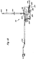
- FIGS 7-11 show part of the steering linkage or a steering device 192 that is effective from the steering means or the steering wheel 28 to the steering control input shaft 104 of the Steering unit 50 of the transmission 46 extends.
- a steering lever 194 is operatively connected to the steering lever 164 in response to to pivot a pivoting movement of the steering wheel 28.
- On Rod member 196 is attached to the steering lever 194 and is firmly connected to a cam element 198.
- the cam element 198 is pivotable about a pivot axis 200, which by the Rod element 196 is determined.
- the cam member 198 defines an arcuate slot 202 in which an end region 204 one of the transmission means mentioned in the claims, elongated element 206 is included.
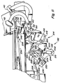
- the elongated element 206 extends from slot 202 in cam member 198 backwards and has a rear end that is pivotally connected to a lever 208 which is connected to the Steering input control shaft 104 of steering unit 50 of transmission 46 connected is. This is elongated when driving forward Element 206 in an upper end region 210 of slot 202 arranged as shown in Figure 11. If that Steering wheel 28 is rotated by the operator, pivot the steering lever 194, the rod member 196 and the cam member 198 about the pivot axis 200 through the axis of the Rod member 196 in a position as shown in Figure 11 is represented, is determined.
- a swiveling of the Cam member 198 causes elongated member 206 in Longitudinal direction generally pressed along its longitudinal shaft or is pulled, whereby the arm 208 pivots and the Steering control input shaft 104 moves. This causes the Steering unit 50 is engaged, causing a vehicle turn is performed.
- a vehicle trip in the reverse Direction is the front end portion 204 of the elongated member 206 in a lower end region 212 of the slot 202 in the Cam element 198 arranged.
- the device shown in Figures 7-11 also provides one Actuator 214 is available, which serves to the front end portion 204 of the elongated member 206 between different arrangements in slot 202 of the To shift cam element 198.
- An actuator 216 is effective with the bottom of the forward pedal 40 connected, which forms part of the pedal linkage.
- the Actuating means 216 has a curved surface or one Slot 218, on which a curve follower 220 rests.
- the Curve follower 220 is connected to a lever element 222, which is pivotally provided on the vehicle 10. With the Lever element 222, a connecting element 224 is connected, which is pivotally held by a switching element 226.
- the switching element 226 becomes pivotable through the cam element 198 worn and has a slot 228 through which the End portion 204 of the elongated member 206 is received.
- a spring mechanism 230 which is a torsion spring 232 has, is attached to the switching element 226 to the Switching element 226 and the elongated element 206 in the direction a neutral position with respect to cam member 198 and to load the slot 202, as shown in Figure 9, which generally elongate member 206 directly with the Pivots axis 200 of cam member 198 aligned.
- a drive linkage 234 provided that extends from the pedals 40, 42 backwards extends.
- the drive linkage 234 has a rod element 236 with a rear end portion on one arm attacks, which is connected to the drive control input shaft 66 is.
- the front area or drive lever 238 of the Bar member 236 is received through a slot 240, which is determined in the first lever 142 of the pedal system.
- a Tension spring 242 extends between the first lever 142 and a portion of the bar member 236 around the bar member 236 toward the rear end of slot 240 strain.
- the steering linkage 192 is located in that shown in FIG Arrangement.
- the front end portion 204 of the elongated member 206 is in a central area 244 of slot 202 of the Cam member 198, and generally with the shaft of the Cam element 198 aligned, arranged. If the Operator in this mode would turn the steering wheel would the steering lever 194, the rod member 196 and that Swing cam member 198 but elongate member 206 would not move in the longitudinal direction since it is with the Pivot axis 200 of the cam element 198 is aligned.
- This feature is advantageous to an operator of it is held to steer the vehicle 10 while beside the vehicle 10 stands. Without this feature, a Operator stand next to the vehicle 10 and the steering wheel 28 rotate, causing the front of the vehicle 10 to do so could be brought to pivot around a turn on to perform the job.
- the steering lever pivot 194, the rod member 196 and the cam member 198 around the Pivot axis 200 of the cam member 198 This causes the upper end of the cam member 198 in the longitudinal direction corresponding to the direction in which the steering wheel 28 is rotated was moved, which in turn caused the elongated element 206 in the longitudinal direction with the upper end of the cam element 198 shifts. Moving the elongated member 206 in Longitudinally swings the arm 208 and the Steering control input shaft 104, which causes the Vehicle 10 takes a turn.
- Reverse mode is elongated member 206 in the lower one Area 212 of slot 202 arranged and the elongated Element 206 will move in the opposite direction to that Move in the direction it would move if the elongated member 206 in the upper region 210 of the Slot 202 would be located when operating in Forward direction took place.
- the steering linkage 192 cause the cam member 198 against the Pivots clockwise, as can be seen from Figure 9, whereby the elongated element 206 is in the upper region 210 of slot 202 pushes backward and arm 208 and the steering control input shaft 104 counterclockwise swing. If the steering wheel 28 while reversing turned to the right, the steering linkage 192 will cause that the cam member 198 pivots counterclockwise whereby the elongated element 206 is in the lower region 212 of slot 202 pushes forward and arm 208 and pivot the steering control input shaft 104 clockwise.
- the steering linkage cause that Cam member 198 pivots clockwise, causing the elongate member 206 in the top portion 210 of the slot 202 moves forward and the arm 208 and the Swivel steering control input shaft 104 clockwise. If the steering wheel 28 rotated to the left during a reverse drive the steering linkage 192 will cause the cam member 198 swiveled clockwise, causing the elongated Element 206 in the lower region 212 of the slot moves backwards and the arm 208 and the Steering control input shaft 204 counterclockwise swivel.
- the steering linkage 192 shown in Figures 7-11 therefore allows the vehicle 10 during a reverse drive to be directed in a way that is similar to that in which a motor vehicle or one steered in the usual way Steers the lawn tractor backwards. If the operator does that Steering wheel 28 to the right either during a forward or reverses, the vehicle 10 turns to turn the operator's right side. If the Operator left the steering wheel 28 either during a forward or reverse drive turns, it will Turn vehicle 10 to the left side of the operator.
- This slot 240 establishes a game in the Drive linkage 234, which requires the forward pedal 40 must be pressed lightly before the drive unit 48 of the gear 46 is engaged.
- the actuator will attack and cause that the elongated member 206 is up in the top End portion 210 of slot 202 is slid before the Drive lever 238 the end of slot 204 in the first Lever 142 reached.
- the steering wheel 28 in the desired direction of Rotation will turn on the spot, but since the forward pedal 40 is not yet pressed, the elongated member 206 is in the central region 244 of the slot 202 in the Cam element 198 is arranged and therefore a pivoting of the Cam member 198 does not displace elongated member 206. The vehicle 10 will therefore not begin to turn.
- the Operator must also press forward pedal 40 to to make a turn. When she starts the forward pedal 40, the actuator 214 begins to press elongate member 206 toward upper end portion 210 the slot 202 to move.
- the Slot 240 in the first lever 142 allows the vehicle make a turn on the spot when the Operator presses forward pedal 40 without doing so Vehicle 10 is driven forward. If the Operator continues to advance pedal 40 further press, then the drive lever 238 is finally on the front end of the slot 240 in the first lever 142 abut, and the rod member 236 will begin after to move backwards at what time the drive unit 48 of the transmission 46 will begin, the vehicle 10 after to propel forward.
- the Pivot axis 200 of cam member 198 generally directly in the center of the slot 202 of the cam member 198 aligned. If the pivot axis 200 of this in Figure 9 position shown forward or backward would be arranged, the range of motion of the steering wheel 28 in be smaller in one direction than the range of motion in the other direction from the straight-ahead driving position. Through a Position the shaft generally directly between the upper and lower end portions of the slot 202 and in generally with a central portion 244 of the slot is aligned the steering wheel 28 by a same range of motion in any direction related to one Straight position to be adjusted.
- the cam member 198 is generally C-shaped when viewed from above, as best seen in Figure 10, which makes it the pivot axis 200 is allowed to be effectively aligned be, that is, in alignment with or generally with one Cutting area of slot 202.
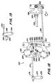
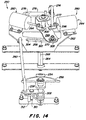
- FIGS. 12-14 in which an alternative embodiment 250 of the Reverse steering mechanism according to the present Invention is presented.
- the alternative embodiment has a steering shaft 252 that extends down from the steering wheel extends, and a steering pinion 254 on one end of the Steering spindle 252.
- the steering pinion 254 meshes with one Sector gear 256 attached to a steering arm 258.
- On C-shaped cam member 262 is pivotable with a front one elongated element 260 connected and is connected to a pivot shaft 264 connected to around the vertically extending shaft 266, which is determined by the pivot shaft 264 to pivot.
- the cam element 262 defines an arcuate slot 268, through which the front end portion 270 of a rod or one rear elongated member 272, which in the claims as Transmission device is called, is recorded.
- the rear portion 274 of the rear elongate member 272 is connected to a steering arm 276, which in turn with the steering control input shaft 278 of the steering unit of the transmission connected is.
- An actuator 280 has forward and Reverse switching devices or electrical solenoids 283, 284 attached to the cam member 262 and be supported by this.
- the solenoids 282, 284 are electrically connected to a switch 286 that is nearby an arm 288 is arranged, which with a Drive control input shaft 290 of the drive unit of the Gearbox is connected.
- Switch 286 has one Actuating pin 292, which is pressed by the arm 288, when the drive input control shaft 290 from a neutral Position pivots backward in response to the Operator presses the reverse pedal 42.
- the switch 286 is actuated when arm 288 is reversed through a small initial range of motion from its neutral position pivots.
- the actuating pin continues into the Switch pushed in.
- the mandrels 294, 296 of the solenoids 282, 284 are connected to a switching element 298 which is pivotable is attached to the cam member 262 via a pin 300.
- the switching element 298 has an opening 302 which the front end portion 270 of the rear elongated member 272 records.
- the reverse solenoid 284 remains de-energized and the forward solenoid 282 is energized, causing the spine 294 of the forward solenoid 282 is forced into the solenoid 282 withdraw, causing the switching element 298 related to the Forward driving direction is pushed to the right. If that Shifting element 298 moves to the right, the front End portion 270 of the rear elongated member 272 in the Slot 268 shifted to the right. The front end portion 270 of the rear elongated member 272 shifts to the right of the shaft 265 and to a right end portion 304 of slot 268 formed in cam member 262.
- the cam member 262 pivot, whereby the rear elongated member 272 also pushes in the direction in which the front elongated Element 260 shifts.
- This activates the steering unit 50 of the transmission 38, and since the operator controls the pedals 40, 42 does not press, the drive unit 48 of the vehicle 10 leads a turn on the spot. If the operator does that Steering wheel 28 continues to rotate, vehicle 10 becomes faster Carry out rotation on the spot.
- the steering unit 50 of the transmission 38 to activate even if the pedals 40, 42 are not depressed, an operator allows the vehicle 10 easy to steer in operating situations when the pedals 40, 42 are not pressed when driving downhill.
- a pretensioner 314 which a tension spring 316 and a set of first and second pins 318, 310 as they are connected to the steering mechanism, operatively connected to the switching element 298.
- the Load spring 316 and the set of pins 318, 320 are used to switch element 298 to a neutral position in which the front end portion 270 of the rear elongated element 272 in the central region 322 of the Slot 268 in the cam member 262 and generally direct is arranged above the shaft 266.
- This embodiment does not allow vehicle 10 to have one Perform rotation on the spot without the Operator presses one of the pedals 40 or 42. This generally prevents an operator from standing next to the Vehicle 10 stands by the fact that steering wheel 28 of vehicle 10 is too rotate and thereby cause the vehicle 10 a Executes rotation on the spot.
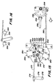
- FIGS. 17 and Fig. 18 shows a cam member 262 with a single solenoid 284 and a loader or a load spring 334 show.
- the spring 334 forces the front end portion 270 of the rear elongated member 272 to the right end portion 304 of the slot 268, thereby establishes correct steering logic in a forward drive mode becomes.
- Invert switch 326 is adjacent arm 288 arranged and engaged when the arm 288 during a Reverse vehicle travel as shown in Figure 18 swings backwards. This energizes the solenoid 284, causing the mandrel 296 is pulled into the solenoid 284, causing the Switching element 298 extends to the left end region 328 of the Slot 268 pivots as shown in Figure 17. This switches the linkage to an operating mode that uses a correct control logic in the reverse direction corresponds.
- FIG. 12-18 represent Switching devices available through electrical actuatable solenoids are formed. However, can Switching device deviating from electrically operated Solenoids can be provided in the spirit of the present invention.
Landscapes
- Engineering & Computer Science (AREA)
- Chemical & Material Sciences (AREA)
- Combustion & Propulsion (AREA)
- Transportation (AREA)
- Mechanical Engineering (AREA)
- Automation & Control Theory (AREA)
- Non-Deflectable Wheels, Steering Of Trailers, Or Other Steering (AREA)
- Steering Control In Accordance With Driving Conditions (AREA)
Abstract
Description

- Fig. 1
- eine Seitenansicht eines als Gartentraktor ausgeführten Fahrzeugs,
- Fig. 2
- eine schematische Ansicht eines Getriebes mit zwei Differentialen,
- Fig. 3
- eine perspektivische Teilansicht von verschiedenen Bereichen des Fahrzeugs aus Figur 1, wobei ein Rahmen, ein Lenkgestänge, ein Pedalgestänge wie auch eine Antriebs- und eine Lenkeinheit des Getriebes dargestellt ist,
- Fig. 4
- eine perspektivische Teilansicht des Fahrzeugs von unten, wobei wiederum der Rahmen, das Lenkgestänge, das Pedalgestänge wie auch die Antriebs- und Lenkeinheit des Getriebes dargestellt ist,
- Fig. 5
- eine perspektivische Ansicht des Fahrzeugs von unten, in der das Pedalgestänge genauer dargestellt ist,
- Fig. 6
- eine perspektivische Ansicht eines Sektorzahnrads, einer Sektorwelle und eines Sektorhebels,
- Fig. 7
- eine perspektivische Ansicht einer alternativen Ausführungsform des in den Figuren 3 - 6 dargestellten Lenkgestänges,
- Fig. 8
- eine perspektivische Ansicht des Lenkgestänges aus Fig. 7 von links in einer neutralen Stellung,
- Fig. 9
- eine Seitenansicht des Lenkgestänges aus Fig. 7 von rechts in einer neutralen Stellung,
- Fig. 10
- eine weitere Ansicht des Lenkgestänges aus Figur 7,
- Fig. 11
- eine Seitenansicht des in den Figuren 7 - 10 gezeigten Lenkgestänges von rechts, wobei das Pedal herunter gedrückt ist,
- Fig. 12
- eine ebene Ansicht einer alternativen Ausführungsform eines Lenkgestänges entsprechend der vorliegenden Erfindung, wobei sich das Gestänge in einer dem herunter gedrückten Pedal zugeordneten Stellung befindet,
- Fig. 13
- eine Seitenansicht eines Umschaltmechanismus, der an die in Figur 12 gezeigte Ausführungsform angepaßt ist,
- Fig. 14
- eine perspektivische Teilansicht des in Figur 12 gezeigten Lenkgestänges,
- Fig. 15
- eine Ansicht einer weiteren alternativen Ausführungsform eines Lenkgestänges entsprechend der vorliegenden Erfindung,
- Fig. 16
- eine Seitenansicht eines Umschaltmechanismus, der an die in Fig. 15 gezeigte Ausführungsform angepaßt ist,
- Fig. 17
- eine Ansicht einer weiteren Ausführungsform eines Lenkgestänges entsprechend der vorliegenden Erfindung,
- Fig. 18
- eine Seitenansicht eines Umschaltmechanismus, der an die in Figur 17 gezeigte Ausführungsform angepaßt ist.
Claims (7)
- Einrichtung zur Lenkung eines Fahrzeugs (10) mit zumindest zwei antreibbaren Rädern (24, 26), mit zumindest einem Lenkmittel, einem Fahrtrichtungswählmittel sowie wenigstens einer Lenkeinheit (50), die mit zumindest einer rechten und einer linken Antriebswelle (84, 86) des Fahrzeugs (10) derart wirksam verbindbar ist, daß die Antriebswellen (84, 86) zur Lenkung des Fahrzeugs (10) mit unterschiedlichen Geschwindigkeiten rotieren, und mit Mitteln zur Invertierung der durch das Lenkmittel eingebrachten Lenkinformation in Abhängigkeit von einer Ausgabe des Fahrtrichtungswählmittels.
- Einrichtung nach Anspruch 1, dadurch gekennzeichnet, daß die Mittel ein verschwenkbares Nockenelement (198) und eine mit dem Nockenelement (198) wirksam verbundene Übertragungseinrichtung aufweisen, wobei die Stellung der Übertragungseinrichtung bezogen auf das Nockenelement (198) vorzugsweise in Abhängigkeit von der Ausgabe des Fahrtrichtungswählmittels veränderbar ist.
- Einrichtung nach Anspruch 2, dadurch gekennzeichnet, daß die Übertragungseinrichtung an dem Nockenelement (198) beweglich vorzugsweise verschieblich angebracht ist und daß Mittel, vorzugsweise in der Art von Anschlägen, zur Begrenzung des Bewegungsbereichs der Übertragungseinrichtung vorgesehen sind, wobei die Drehwelle des Nockenelements (198) vorzugsweise zwischen den Anschlägen und von diesen zumindest im wesentlichen gleich beabstandet angeordnet ist.
- Einrichtung nach Anspruch 2 oder 3, gekennzeichnet durch Mittel, die die Übertragungseinrichtung in Richtung einer Neutralstellung belasten.
- Einrichtung nach einem oder mehreren der Ansprüche 2 bis 4, dadurch gekennzeichnet, daß die Stellung der Übertragungseinrichtung bezogen auf das Nockenelement (198) mittels eines durch das Fahrtrichtungswählmittel direkt oder indirekt verstell- vorzugsweise verschwenkbaren Hebelelements (222) und/oder einer oder mehrerer durch das Fahrtrichtungswählmittel ansteuerbaren Betätigungseinrichtung(en), die beispielsweise in der Art von Aktoren, wie Solenoiden, Hydraulik- bzw. Pneumatikmotoren, ausgeführt sind, bestimmbar ist.
- Einrichtung nach einem oder mehreren der vorherigen Ansprüche, dadurch gekennzeichnet, daß wenigstens die Lenkeinheit (50) einen hydrostatischen Antrieb (62, 94) aufweist und daß die Übertragungseinrichtung vorzugsweise direkt oder indirekt auf eine Pumpe (64, 96) des hydrostatischen Antriebs (62, 94) wirkt.
- Fahrzeug (10) vorzugsweise zur Rasen-, Garten- bzw. Grundstückspflege mit einer Einrichtung nach einem oder mehreren der vorherigen Ansprüche.
Applications Claiming Priority (4)
| Application Number | Priority Date | Filing Date | Title |
|---|---|---|---|
| US09/277,346 US6129164A (en) | 1999-03-26 | 1999-03-26 | Mechanism for correct steering in reverse |
| US277346 | 1999-03-26 | ||
| US09/412,924 US6196342B1 (en) | 1999-03-26 | 1999-10-05 | Mechanism for correct steering in reverse |
| US412924 | 2003-04-14 |
Publications (2)
| Publication Number | Publication Date |
|---|---|
| EP1038757A2 true EP1038757A2 (de) | 2000-09-27 |
| EP1038757A3 EP1038757A3 (de) | 2004-02-04 |
Family
ID=26958430
Family Applications (1)
| Application Number | Title | Priority Date | Filing Date |
|---|---|---|---|
| EP00106001A Withdrawn EP1038757A3 (de) | 1999-03-26 | 2000-03-27 | Einrichtung zur Lenkung eines Fahrzeugs und Fahrzeug |
Country Status (1)
| Country | Link |
|---|---|
| EP (1) | EP1038757A3 (de) |
Cited By (2)
| Publication number | Priority date | Publication date | Assignee | Title |
|---|---|---|---|---|
| DE102007001943B4 (de) * | 2006-01-17 | 2012-05-31 | General Motors Corp. | Lenkverfahren für ein Kettenfahrzeug |
| RU208122U1 (ru) * | 2021-03-18 | 2021-12-03 | Общество С Ограниченной Ответственностью Научно-Производственное Объединение "Транспорт" | Двухпоточная трансмиссия гусеничной машины |
Family Cites Families (8)
| Publication number | Priority date | Publication date | Assignee | Title |
|---|---|---|---|---|
| US1247725A (en) * | 1915-12-28 | 1917-11-27 | Eugene Schneider | Power-transmitting and steering mechanism for caterpillar-tractors. |
| DE2948214A1 (de) * | 1979-11-30 | 1981-06-04 | Dr.Ing.H.C. F. Porsche Ag, 7000 Stuttgart | Vorrichtung zum steuern einer lenkung fuer gleiskettenfahrzeuge |
| CA1325955C (en) * | 1988-09-17 | 1994-01-11 | Jerry Richard Duncan | System for controlling the ground speed and direction of travel of an off-road vehicle |
| JP3017576B2 (ja) * | 1991-10-04 | 2000-03-13 | 株式会社クボタ | 歩行型作業機 |
| JP3160751B2 (ja) * | 1995-07-20 | 2001-04-25 | 本田技研工業株式会社 | 無段変速駆動車両における操舵制御装置 |
| GB2303829A (en) * | 1995-08-03 | 1997-03-05 | Environmental Engineering Grou | Vehicle skid-steer control system |
| DE69738924D1 (de) * | 1997-01-23 | 2008-10-02 | Yanmar Agricult Equip | Mobile landbaumaschine |
| EP1129310A4 (de) * | 1998-09-25 | 2007-05-02 | Tuff Torq Corp | Getriebe zur geschwindigkeitsveränderung und steuerung eines fahrzeugs |
-
2000
- 2000-03-27 EP EP00106001A patent/EP1038757A3/de not_active Withdrawn
Cited By (2)
| Publication number | Priority date | Publication date | Assignee | Title |
|---|---|---|---|---|
| DE102007001943B4 (de) * | 2006-01-17 | 2012-05-31 | General Motors Corp. | Lenkverfahren für ein Kettenfahrzeug |
| RU208122U1 (ru) * | 2021-03-18 | 2021-12-03 | Общество С Ограниченной Ответственностью Научно-Производственное Объединение "Транспорт" | Двухпоточная трансмиссия гусеничной машины |
Also Published As
| Publication number | Publication date |
|---|---|
| EP1038757A3 (de) | 2004-02-04 |
Similar Documents
| Publication | Publication Date | Title |
|---|---|---|
| EP1038759A2 (de) | Einrichtung zur Lenkung eines Fahrzeugs und Fahrzeug | |
| EP1038762A2 (de) | Fahrzeug, insbesondere Rasenmäher, mit günstiger Gewichtsverteilung | |
| DE69611208T2 (de) | Lenkeinrichtung für ein Fahrzeug mit stufenlosem Getriebe | |
| DE19522877B4 (de) | Antriebsgetriebe für Arbeitsfahrzeuge | |
| EP1038756A2 (de) | Getriebe zum Antreiben von Rädern mit unterschiedlichen Geschwindigkeiten | |
| EP1038758A2 (de) | Fahrzeug, bei dem die Räder mit unterschiedlichen Geschwindigkeiten angetrieben werden | |
| DE2361786A1 (de) | Traktor bzw. motorschlepper mit unterrahmen zum hantieren von material | |
| DE60316528T2 (de) | Hydraulische Vierradantriebsvorrichtung | |
| DE2425777A1 (de) | Fahrzeug mit eigenem antrieb, insbesondere frontlader oder gabelstapler | |
| DE3020956A1 (de) | Schlepper | |
| CH652666A5 (de) | Hydraulikmotor-angetriebenes, zweiteiliges, gelaendegaengiges fahrzeug. | |
| DE3532830A1 (de) | Motorrasenmaeher | |
| DE2314882A1 (de) | Antriebsmechanismus | |
| DE2652823A1 (de) | Bremsgelenktes fahrzeug, insbesondere zugmaschine, mit lenkhebel und einer hilfssteuerung mit selbstzentriervorrichtung | |
| DE2025607A1 (de) | Vorrichtung zur Änderung der Drehzahl oder der Drehrichtung der Antriebsvorrichtung eines Kraftfahrzeuges. | |
| CH619897A5 (de) | ||
| DE69524803T2 (de) | Arbeitswagen | |
| DE69418951T2 (de) | Arbeitsfahrzeug | |
| DE69103873T2 (de) | Fahrzeug mit Mischlenkung. | |
| DE69527572T2 (de) | Betätigungsvorrichtung in einem Fahrzeug mit zwei stufenlosen Getrieben | |
| DE1581066B1 (de) | Schaufellader mit einem die hydraulischen Betaetigungszylinder und die beidseitigen Fahr- und Lenkantriebe des Traegerfahrzeuges schaltenden,durch Mehrfunktionshebel gebildeten Handsteuergestaenge | |
| DE69635839T2 (de) | Ansteuervorrichtung für arbeitsfahrzeug | |
| DE2345622C3 (de) | Antriebs- und Lenkgetriebe einer Zugmaschine für Erdbewegungsarbeiten o.dgl | |
| DE3928670A1 (de) | Geschwindigkeitsregeleinrichtung fuer fahrzeuge | |
| DE3142786A1 (de) | Wechselgetriebe fuer einen traktor |
Legal Events
| Date | Code | Title | Description |
|---|---|---|---|
| PUAI | Public reference made under article 153(3) epc to a published international application that has entered the european phase |
Free format text: ORIGINAL CODE: 0009012 |
|
| AK | Designated contracting states |
Kind code of ref document: A2 Designated state(s): AT BE CH CY DE DK ES FI FR GB GR IE IT LI LU MC NL PT SE |
|
| AX | Request for extension of the european patent |
Free format text: AL;LT;LV;MK;RO;SI |
|
| PUAL | Search report despatched |
Free format text: ORIGINAL CODE: 0009013 |
|
| AK | Designated contracting states |
Kind code of ref document: A3 Designated state(s): AT BE CH CY DE DK ES FI FR GB GR IE IT LI LU MC NL PT SE |
|
| AX | Request for extension of the european patent |
Extension state: AL LT LV MK RO SI |
|
| AKX | Designation fees paid | ||
| REG | Reference to a national code |
Ref country code: DE Ref legal event code: 8566 |
|
| STAA | Information on the status of an ep patent application or granted ep patent |
Free format text: STATUS: THE APPLICATION IS DEEMED TO BE WITHDRAWN |
|
| 18D | Application deemed to be withdrawn |
Effective date: 20040805 |