EP1038592B1 - Vorrichtung zur dosierten Abgabe von strömenden Medien - Google Patents
Vorrichtung zur dosierten Abgabe von strömenden Medien Download PDFInfo
- Publication number
- EP1038592B1 EP1038592B1 EP00104621A EP00104621A EP1038592B1 EP 1038592 B1 EP1038592 B1 EP 1038592B1 EP 00104621 A EP00104621 A EP 00104621A EP 00104621 A EP00104621 A EP 00104621A EP 1038592 B1 EP1038592 B1 EP 1038592B1
- Authority
- EP
- European Patent Office
- Prior art keywords
- intermediate plate
- applicator head
- plate
- channel
- applicator
- Prior art date
- Legal status (The legal status is an assumption and is not a legal conclusion. Google has not performed a legal analysis and makes no representation as to the accuracy of the status listed.)
- Expired - Lifetime
Links
- 239000012530 fluid Substances 0.000 title 1
- 239000000758 substrate Substances 0.000 claims description 8
- 239000000853 adhesive Substances 0.000 claims description 6
- 230000001070 adhesive effect Effects 0.000 claims description 6
- 239000004831 Hot glue Substances 0.000 claims description 2
- 238000003780 insertion Methods 0.000 claims description 2
- 230000037431 insertion Effects 0.000 claims description 2
- 239000000314 lubricant Substances 0.000 claims description 2
- 239000007921 spray Substances 0.000 claims description 2
- 239000003973 paint Substances 0.000 claims 1
- 239000003292 glue Substances 0.000 description 13
- 240000006829 Ficus sundaica Species 0.000 description 1
- 239000003086 colorant Substances 0.000 description 1
- 230000001419 dependent effect Effects 0.000 description 1
- 238000006073 displacement reaction Methods 0.000 description 1
- 239000007788 liquid Substances 0.000 description 1
- 238000000034 method Methods 0.000 description 1
- 238000007789 sealing Methods 0.000 description 1
Images


Classifications
-
- B—PERFORMING OPERATIONS; TRANSPORTING
- B05—SPRAYING OR ATOMISING IN GENERAL; APPLYING FLUENT MATERIALS TO SURFACES, IN GENERAL
- B05C—APPARATUS FOR APPLYING FLUENT MATERIALS TO SURFACES, IN GENERAL
- B05C5/00—Apparatus in which liquid or other fluent material is projected, poured or allowed to flow on to the surface of the work
- B05C5/02—Apparatus in which liquid or other fluent material is projected, poured or allowed to flow on to the surface of the work the liquid or other fluent material being discharged through an outlet orifice by pressure, e.g. from an outlet device in contact or almost in contact, with the work
- B05C5/027—Coating heads with several outlets, e.g. aligned transversally to the moving direction of a web to be coated
- B05C5/0275—Coating heads with several outlets, e.g. aligned transversally to the moving direction of a web to be coated flow controlled, e.g. by a valve
- B05C5/0279—Coating heads with several outlets, e.g. aligned transversally to the moving direction of a web to be coated flow controlled, e.g. by a valve independently, e.g. individually, flow controlled
-
- B—PERFORMING OPERATIONS; TRANSPORTING
- B05—SPRAYING OR ATOMISING IN GENERAL; APPLYING FLUENT MATERIALS TO SURFACES, IN GENERAL
- B05B—SPRAYING APPARATUS; ATOMISING APPARATUS; NOZZLES
- B05B15/00—Details of spraying plant or spraying apparatus not otherwise provided for; Accessories
- B05B15/60—Arrangements for mounting, supporting or holding spraying apparatus
- B05B15/65—Mounting arrangements for fluid connection of the spraying apparatus or its outlets to flow conduits
-
- B—PERFORMING OPERATIONS; TRANSPORTING
- B05—SPRAYING OR ATOMISING IN GENERAL; APPLYING FLUENT MATERIALS TO SURFACES, IN GENERAL
- B05B—SPRAYING APPARATUS; ATOMISING APPARATUS; NOZZLES
- B05B15/00—Details of spraying plant or spraying apparatus not otherwise provided for; Accessories
- B05B15/60—Arrangements for mounting, supporting or holding spraying apparatus
- B05B15/68—Arrangements for adjusting the position of spray heads
-
- B—PERFORMING OPERATIONS; TRANSPORTING
- B05—SPRAYING OR ATOMISING IN GENERAL; APPLYING FLUENT MATERIALS TO SURFACES, IN GENERAL
- B05C—APPARATUS FOR APPLYING FLUENT MATERIALS TO SURFACES, IN GENERAL
- B05C11/00—Component parts, details or accessories not specifically provided for in groups B05C1/00 - B05C9/00
- B05C11/10—Storage, supply or control of liquid or other fluent material; Recovery of excess liquid or other fluent material
-
- B—PERFORMING OPERATIONS; TRANSPORTING
- B05—SPRAYING OR ATOMISING IN GENERAL; APPLYING FLUENT MATERIALS TO SURFACES, IN GENERAL
- B05C—APPARATUS FOR APPLYING FLUENT MATERIALS TO SURFACES, IN GENERAL
- B05C5/00—Apparatus in which liquid or other fluent material is projected, poured or allowed to flow on to the surface of the work
- B05C5/001—Apparatus in which liquid or other fluent material is projected, poured or allowed to flow on to the surface of the work incorporating means for heating or cooling the liquid or other fluent material
Definitions
- the invention relates to a device for metered delivery of flowing media, in particular hot melt adhesive, cold glue, lubricants, Colors od.
- a device for metered delivery of flowing media in particular hot melt adhesive, cold glue, lubricants, Colors od.
- the boundary surface having, in the numerous spaced, arranged in a row, for a flowing medium provided feed channels open, of which at least one by means of an intermediate plate with a job module connected, which with a nozzle head for applying adhesive dots, Glue lines or adhesive areas on a moving past substrate is provided, wherein each intermediate plate a the distance at least two supply channels bridging channel and a mounting position for the job module.
- the object of the invention is a device for metered Provision of flowing media to create the order modules with least effort can be attached in any position.
- the applicator head a running parallel to the feed channels guide groove in the at least one sliding block is arranged with the intermediate plate is connected to movement.
- this technical solution can by Partial release of the connection between the intermediate plate and the sliding block only by a lateral displacement of the intermediate plate including Order module to be made a new positioning.
- a further advantageous embodiment of the invention is the directed to the applicator head surface of the intermediate plate with a groove for Insertion of a flat gasket having the bypass channel Mistake.
- the top said groove incorporated in the direction of the applicator head surface be, wherein in the unloaded state slightly protruding from the groove, also easy to produce flat gasket only in the groove must be inserted.
- the groove on both sides, each having a on a side surface of the Intermediate plate arranged closure plate be limited, so that a accurate positioning of the gasket in the groove is achievable.
- the aforementioned embodiment can be varied in that in the order of the head facing surface of the intermediate plate only one Countersink is incorporated, in the one with a bypass channel provided flat gasket is used.
- a further preferred embodiment of the invention has the intermediate plate via an intregr convinced air connection, which over a Directional valve and a flexible hose and a pneumatic connector to a parallel to the boundary surface of the gun extending compressed air pipe is connected. Because of this easily convertible and flexible compressed air infrastructure will change the position of the intermediate plate and thus further simplifies one or more order modules and finally the possibility of movement of the intermediate plate clearly extended.
- a device for metered delivery of flowing media designated overall by the reference numeral 10.
- Such a device 10 has an applicator head 11, at least an intermediate plate 12 and an order module 13, which with a Nozzle head 14 is provided.
- Fig. 1 is a perspective view of such a device 10th shown.
- One recognizes a boundary surface 15 of the application head 11, which is provided with a horizontally extending T-shaped sliding groove 16.
- the intermediate plate 12 described below Way is attached to the boundary surface 15, the order module 13th merely connected by screws S to the intermediate plate 12.
- a plate 19 can be seen on a lower surface 18, which, among other things, as a guide for an unrepresented, below the Nozzle head through migrating substrate, e.g. a blank of a folding carton, is provided.
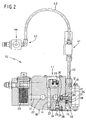
- Fig. 2 the device 10 is shown in detail, with only those elements to be described below, the one Reference to the invention.
- Feeding the via the order module 13 controlled quantities to be dispensed first takes place via a filter block 20 and a connection channel 21 to the pressure distribution channel 22, the again via a further channel 23 with a main distribution channel 24th connected is.
- From the main distribution channel 24 go numerous glue supply channels 25, which - as shown in Fig. 1 - arranged in series in the Open the boundary surface 15.
- each feed channel 25 via a with an O-ring provided screw plug 26 can be blocked.
- the Closure screw 26 is seated in a vertically in the lower surface 18th arranged bore 27 adjacent to the lower surface 18 is the plate 19th fastened with screws 28.
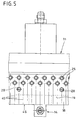
- the plate 19 has holes 29 which with arranged in series holes 27 for the screw plugs 26 (s. Fig. 5) are aligned and compared to the screw plugs 26 undersize exhibit. This has the technical meaning that the plate 19 an additional Has function as a backup plate for the screw plug 26.
- a socket wrench it is namely possible, as a hexagon socket screw trained closure screw 26 depending on the position of To bring intermediate plate 12 in a closed or in an open position. When you open the screw plug 26 is the undersize having Bore 27 as an opening stop for the screw plug 26, wherein this attack at the same time the loss of screw plugs 26th prevented.
- the intermediate plate 12 is attached.
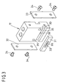
- the Intermediate plate 12 is shown in detail in Fig. 3.
- the bypass channel 32 is connected to a Provision channel 39 provided after the use of the gasket 31 in the Groove 30 is aligned with a channel 38 in the intermediate plate 12.
- After Positioning of the gasket 31 in the groove 30 may be lateral Locking plates 33 with respective screws 34 on the intermediate plate 12th be attached.
- the intermediate plate 12 By attaching the intermediate plate 12 to the boundary surface 15 creates an extension of the feed channel 25th in that the bridging channel 32 is provided with the branch channel 39 which is a connection to the channel section 38 in the hiss plate 12th creates. Since the order module 13 in a manner not shown a likewise Having corresponding glue supply channel, is thus the Glue supply secured to the nozzle head 14.
- FIG. 4 In the front view of FIG. 4 it can be seen that after Attachment of the intermediate plate 12 including job module 13 on the in the flat gasket 31 arranged bridging channel 32 a Glue feed into the order module 13 and the nozzle head 14th is possible. There is dashed the bypass channel 32 is shown, the extends over three glue supply channels 25 in this case. By Opening one of the channels 25 by means of an associated hexagon screw 26th then results in a continuous channel for the supply of glue up in the nozzle head 14.
- the intermediate plate 12 and Order module 13 formed unit to the left or right in each to move the desired position, in each case always two supply channels 25 for the glue supply of the nozzle head 14 available stand.
- the device 10 is fragmentary in the See bottom view.
- These markings 45 now make it possible to easy way to recognize which screw plug 26 and thus which supply channel 25 must be opened so that the supply of the Assured at a certain position order module 13 ensured is.
Landscapes
- Coating Apparatus (AREA)
- Reciprocating Pumps (AREA)
- Application Of Or Painting With Fluid Materials (AREA)
- Nozzles (AREA)
Description
Claims (11)
- Vorrichtung (10) zur dosierten Abgabe von strömenden Medien, insbesondere Schmelzkleber, Kaltleim, Schmierstoffe, Farben od. dgl., mit einem Auftragskopf (11), der eine Begrenzungsfläche (15) aufweist, in der zahlreiche beabstandete, in einer Reihe angeordnete, für ein strömendes Medium vorgesehene Zuführungskanäle (17, 25) münden, von denen mindestens einer mittels einer Zwischenplatte (12) mit einem Auftragsmodul (13) verbunden ist, welches mit einem Düsenkopf (14) zur Aufbringung von Klebepunkten, Klebelinien bzw. Klebebereiche auf ein vorbeibewegtes Substrat versehen ist, wobei jede Zwischenplatte (12) eine Montageposition für das Auftragsmodul (13) zur Verfügung stellt, dadurch gekennzeichnet, daß die Zwischenplatte (12) an der Begrenzungsfläche (15) entlang der Mündungen der Zuführkanäle (25) am Auftragskopf (11) stufenlos verstellbar angeordnet ist und dass die Zwischenplatte eines den Abstand mindestens zweier Zuführungskanäle (17, 25) überbrückenden Kanal (32) aufweist.
- Vorrichtung nach Anspruch 1, dadurch gekennzeichnet, daß der Auftragskopf (11) eine parallel zu den Zuführkanälen (25) verlaufende Führungsnut aufweist, in der mindestens ein Nutenstein (37) angeordnet ist, der mit der Zwischenplatte (12) bewegungsverbunden ist.
- Vorrichtung nach Anspruch 1 oder 2, dadurch gekennzeichnet, daß die zum Auftragskopf (11) gerichteten Fläche der Zwischenplatte (12) mit einer Nut (30) zum Einschub einer den Überbrückungskanal (32) aufweisenden Flachdichtung (31) versehen ist.
- Vorrichtung nach Anspruch 3, dadurch gekennzeichnet, daß die Nut (30) zur Aufnahme der Flachdichtung (31) beidseitig mit jeweils einer an einer Seitenfläche der Zwischenplatte (12) angeordneten Verschlußplatte (33) begrenzt ist.
- Vorrichtung nach Anspruch 1 oder 2, dadurch gekennzeichnet, daß in die zum Auftragskopf (11) weisende Fläche der Zwischenplatte (12) ein Überbrückungskanal (32) eingearbeitet ist, weicher lediglich durch die Befestigung der Zwischenplatte (12) am Auftragskopf (11) abdichtbar ist.
- Vorrichtung nach Anspruch 1 oder 2, dadurch gekennzeichnet, daß in die zum Auftragskopf (11) weisenden Fläche der Zwischenplatte (12) eine Einsenkung eingearbeitet ist, in die eine mit einem Überbrückungskanal (32) versehene Flachdichtung (31) einsetzbar ist.
- Vorrichtung nach einem der vorangehenden Ansprüche, dadurch gekennzeichnet, daß die Zwischenplatte (12) über einen integrierten Luftanschluß (40) verfügt, der über ein Wegeventil (41) und einen flexiblen Schlauch (42) sowie eine Pneumatiksteckverbindung (43) an ein parallel zur Begrenzungsfläche (15) des Auftragskopfes (11) verlaufendes Druckluftrohr (44) anschließbar ist.
- Vorrichtung nach einem der Ansprüche 1 bis 6, dadurch gekennzeichnet, daß die Zwischenplatte (12) über einen separaten Sprühluftanschluß gemäß Anspruch 7 verfügt.
- Vorrichtung nach einem der vorangehenden Ansprüche, dadurch gekennzeichnet, daß an einer Unterfläche (18) des Auftragskopfes (11) ein in Richtung des Auftragsmoduls (13) hervorragende Platte (19) angeordnet ist, die der Führung des Substrats dient.
- Vorrichtung nach Anspruch 9, dadurch gekennzeichnet, daß die Platte (19) zusätzlich Bohrungen (29) aufweist, die mit in der Unterfläche angeordneten Bohrungen (27) zur Aufnahme von Verschlußschrauben (26) für die Zuführkanäle (25) fluchten, jedoch gegenüber den Verschlußschrauben (26) Untermaß aufweisen.
- Vorrichtung nach Anspruch 9 oder 10, dadurch gekennzeichnet, daß die Platte (19) des weiteren an ihrer Unterseite (18) Hilfslinien (45) aufweist, die jeweils von der Mittelachse einer Verschlußschraube (26) eines Zuführungskanal (25) bis zu einer zur Düse (14) eines Auftragsmoduls (13) weisenden Begrenzungskante (46) verlaufen.
Applications Claiming Priority (2)
| Application Number | Priority Date | Filing Date | Title |
|---|---|---|---|
| DE19913159A DE19913159C1 (de) | 1999-03-24 | 1999-03-24 | Vorrichtung zur dosierten Abgabe von strömenden Medien |
| DE19913159 | 1999-03-24 |
Publications (3)
| Publication Number | Publication Date |
|---|---|
| EP1038592A2 EP1038592A2 (de) | 2000-09-27 |
| EP1038592A3 EP1038592A3 (de) | 2004-03-24 |
| EP1038592B1 true EP1038592B1 (de) | 2005-12-28 |
Family
ID=7902127
Family Applications (1)
| Application Number | Title | Priority Date | Filing Date |
|---|---|---|---|
| EP00104621A Expired - Lifetime EP1038592B1 (de) | 1999-03-24 | 2000-03-03 | Vorrichtung zur dosierten Abgabe von strömenden Medien |
Country Status (4)
| Country | Link |
|---|---|
| US (1) | US6358322B1 (de) |
| EP (1) | EP1038592B1 (de) |
| JP (1) | JP4607279B2 (de) |
| DE (1) | DE19913159C1 (de) |
Families Citing this family (16)
| Publication number | Priority date | Publication date | Assignee | Title |
|---|---|---|---|---|
| US6814315B2 (en) * | 2001-08-30 | 2004-11-09 | Nordson Corporation | Liquid dispensing manifold with adjustable slide plate |
| US20050015050A1 (en) * | 2003-07-15 | 2005-01-20 | Kimberly-Clark Worldwide, Inc. | Apparatus for depositing fluid material onto a substrate |
| DE10353916A1 (de) * | 2003-11-18 | 2005-06-09 | Wilhelm Schulte Gmbh | Verfahren zum Verkleben von Textilien |
| US7296706B2 (en) * | 2004-02-24 | 2007-11-20 | Nordson Corporation | Method and system for supporting and/or aligning components of a liquid dispensing system |
| USD536421S1 (en) | 2004-04-02 | 2007-02-06 | Nordson Corporation | Intake portion of a liquid dispensing valve |
| US7278550B2 (en) * | 2004-11-11 | 2007-10-09 | Nordson Corporation | Method and system for aligning components of a liquid dispensing system |
| USD552716S1 (en) | 2005-06-29 | 2007-10-09 | Nordson Corporation | Dispensing valve |
| DE202007002156U1 (de) * | 2007-02-09 | 2007-04-12 | Nordson Corp | Vorrichtung zum Auftragen von Fluiden wie Klebstoff |
| US8474660B2 (en) * | 2006-11-15 | 2013-07-02 | Nordson Corporation | Dispensing apparatus having a pivot actuator |
| US8061564B2 (en) * | 2006-11-15 | 2011-11-22 | Nordson Corporation | Liquid dispensing apparatus including an attachment member |
| DE102008001064A1 (de) | 2008-04-08 | 2009-10-15 | Voith Patent Gmbh | Bespannung und Verfahren zu deren Herstellung |
| DE202013100352U1 (de) * | 2013-01-25 | 2014-04-28 | Baumer Hhs Gmbh | Auftragseinrichtung zum Auftrag von fluidem Medium auf ein Substrat |
| CN107262331A (zh) * | 2017-05-31 | 2017-10-20 | 嘉善宝狐服饰有限公司 | 一种工件预固定装置 |
| CN109647663A (zh) * | 2019-02-14 | 2019-04-19 | 宁波高新区晖云电子科技有限公司 | 一种led灯自动化安装注胶装置 |
| CN111672709B (zh) * | 2020-07-03 | 2021-04-30 | 江西奥普照明有限公司 | 一种生产led灯管的双堵头自动上料打胶机 |
| USD1079896S1 (en) * | 2021-04-30 | 2025-06-17 | Nordson Corporation | Applicator module |
Family Cites Families (10)
| Publication number | Priority date | Publication date | Assignee | Title |
|---|---|---|---|---|
| US3570725A (en) * | 1968-11-15 | 1971-03-16 | Nordson Corp | Applicator having a fixed module with static parts and a removable module with moving parts |
| US4710399A (en) * | 1986-09-02 | 1987-12-01 | Dennis Richard K | Method and mechanism to deposit solder paste upon substrates |
| ATE168067T1 (de) * | 1992-02-13 | 1998-07-15 | Accurate Prod Co | Schmelzblasdüse mit voreinstellbaren luftspakt und rückstellung |
| US5265800A (en) * | 1993-01-25 | 1993-11-30 | Nordson Corporation | Adhesive spray gun with adjustable module and method of assembling |
| US5683037A (en) * | 1994-12-30 | 1997-11-04 | Nordson Corporation | Adhesive spray gun system with individually adjustable spray modules |
| DE19504119C2 (de) * | 1995-02-08 | 2000-07-13 | S Rockstedt Gmbh Maschf | Am Ausgang eines Extruders angebrachter Düsenkopf |
| US5720418A (en) * | 1995-08-14 | 1998-02-24 | Illinois Tool Works Inc. | Adjustable tool for dispensing viscous material, such as two-part adhesive |
| US5862986A (en) * | 1996-07-16 | 1999-01-26 | Illinois Tool Works, Inc. | Hot melt adhesive applicator with metering gear-driven head |
| US5823437A (en) * | 1996-07-16 | 1998-10-20 | Illinois Tool Works Inc. | Fluid flow control plates for hot melt adhesive applicator |
| US5806720A (en) * | 1996-07-19 | 1998-09-15 | Illinois Tool Works Inc. | Multi position palletizer head for adhesive supply unit |
-
1999
- 1999-03-24 DE DE19913159A patent/DE19913159C1/de not_active Expired - Lifetime
-
2000
- 2000-03-03 EP EP00104621A patent/EP1038592B1/de not_active Expired - Lifetime
- 2000-03-22 JP JP2000084711A patent/JP4607279B2/ja not_active Expired - Fee Related
- 2000-03-22 US US09/533,116 patent/US6358322B1/en not_active Expired - Fee Related
Also Published As
| Publication number | Publication date |
|---|---|
| EP1038592A3 (de) | 2004-03-24 |
| JP2000312852A (ja) | 2000-11-14 |
| JP4607279B2 (ja) | 2011-01-05 |
| EP1038592A2 (de) | 2000-09-27 |
| DE19913159C1 (de) | 2000-07-20 |
| US6358322B1 (en) | 2002-03-19 |
Similar Documents
| Publication | Publication Date | Title |
|---|---|---|
| DE19913159C1 (de) | Vorrichtung zur dosierten Abgabe von strömenden Medien | |
| DE69531724T2 (de) | Klebstoffspritzapparat mit einzeln einstellbaren Sprüheinheiten | |
| DE69329539T2 (de) | Spritzpistole für Substratbeschichtung | |
| DE19830728C2 (de) | Kleber-Auftragsvorrichtung | |
| WO2002087779A1 (de) | Spritzeinrichtung zum versprühen von flüssigkeiten, insbesondere für landwirtschaftliche zwecke | |
| DE202012008272U1 (de) | Vorrichtung zum Aufbringen eines Fluids | |
| DE202004007024U1 (de) | Auftragskopf, Auftragsdüsenanordnung, Adapterplatte sowie Montageplatte | |
| EP0224855A2 (de) | Schlitzdüse | |
| DE69327315T2 (de) | Verfahren und vorrichtung zum auftragen von fluid, insbesondere von hot melt, auf ein substrat durch ein sequentielles auftragegerät | |
| EP1886939A2 (de) | Abgabekopf für einen Druckbehälter | |
| EP0224916A1 (de) | Vorrichtung zum intermittierenden Auftragen von flüssigem Klebstoff | |
| DE102006005341B4 (de) | Lackiervorrichtung sowie Farbwechseleinrichtung für eine Lackiervorrichtung | |
| EP0744220B1 (de) | Schlitzdüse | |
| DE29907968U1 (de) | Vorrichtung zum Abgeben von Fluid, insbesondere Klebstoff | |
| EP0366962B1 (de) | Schlitzdüse | |
| DE10046326B4 (de) | Vorrichtung zum Auftragen von Fluid, insbesondere Heissschmelzklebstoff, auf ein relativ zu der Vorrichtung bewegbares Substrat | |
| EP2948382B1 (de) | Auftragseinrichtung zum auftrag von fluidem medium auf ein substrat | |
| DE29905345U1 (de) | Vorrichtung zur dosierten Abgabe von strömenden Medien | |
| EP1070551B1 (de) | Vorrichtung zur dosierten Abgabe von strömenden Medien | |
| DE19617479A1 (de) | Vorrichtung zur Erzeugung eines einstellbaren Flüssigkeitsstrahls | |
| DE19914040A1 (de) | Sprühpistolen-Roboter-Adapter | |
| DE9315652U1 (de) | Auftragskopf zum Aufbringen von Klebstoff auf ein Substrat, insbesondere für eine Verklebung eines Chips mit einer Karte | |
| DE1650371B2 (de) | Unmittelbar an einem druckmittelverbraucher befestigte ventileinheit | |
| DE3929503C2 (de) | ||
| DE9316085U1 (de) | Auftragskopf für das Aufbringen von Kaltleim auf ein Substrat |
Legal Events
| Date | Code | Title | Description |
|---|---|---|---|
| PUAI | Public reference made under article 153(3) epc to a published international application that has entered the european phase |
Free format text: ORIGINAL CODE: 0009012 |
|
| AK | Designated contracting states |
Kind code of ref document: A2 Designated state(s): AT BE CH CY DE DK ES FI FR GB GR IE IT LI LU MC NL PT SE |
|
| AX | Request for extension of the european patent |
Free format text: AL;LT;LV;MK;RO;SI |
|
| RAP1 | Party data changed (applicant data changed or rights of an application transferred) |
Owner name: ITW DYNATEC GMBH |
|
| PUAL | Search report despatched |
Free format text: ORIGINAL CODE: 0009013 |
|
| AK | Designated contracting states |
Kind code of ref document: A3 Designated state(s): AT BE CH CY DE DK ES FI FR GB GR IE IT LI LU MC NL PT SE |
|
| AX | Request for extension of the european patent |
Extension state: AL LT LV MK RO SI |
|
| RIC1 | Information provided on ipc code assigned before grant |
Ipc: 7B 05B 15/06 B Ipc: 7B 05C 5/02 A |
|
| 17P | Request for examination filed |
Effective date: 20040405 |
|
| REG | Reference to a national code |
Ref country code: DE Ref legal event code: 8566 |
|
| 17Q | First examination report despatched |
Effective date: 20040831 |
|
| AKX | Designation fees paid |
Designated state(s): CH FR GB LI NL SE |
|
| GRAP | Despatch of communication of intention to grant a patent |
Free format text: ORIGINAL CODE: EPIDOSNIGR1 |
|
| GRAC | Information related to communication of intention to grant a patent modified |
Free format text: ORIGINAL CODE: EPIDOSCIGR1 |
|
| GRAS | Grant fee paid |
Free format text: ORIGINAL CODE: EPIDOSNIGR3 |
|
| GRAA | (expected) grant |
Free format text: ORIGINAL CODE: 0009210 |
|
| AK | Designated contracting states |
Kind code of ref document: B1 Designated state(s): CH FR GB LI NL SE |
|
| REG | Reference to a national code |
Ref country code: GB Ref legal event code: FG4D Free format text: NOT ENGLISH |
|
| REG | Reference to a national code |
Ref country code: CH Ref legal event code: EP |
|
| REG | Reference to a national code |
Ref country code: SE Ref legal event code: TRGR |
|
| GBT | Gb: translation of ep patent filed (gb section 77(6)(a)/1977) |
Effective date: 20051229 |
|
| REG | Reference to a national code |
Ref country code: CH Ref legal event code: NV Representative=s name: E. BLUM & CO. PATENTANWAELTE |
|
| ET | Fr: translation filed | ||
| PLBE | No opposition filed within time limit |
Free format text: ORIGINAL CODE: 0009261 |
|
| STAA | Information on the status of an ep patent application or granted ep patent |
Free format text: STATUS: NO OPPOSITION FILED WITHIN TIME LIMIT |
|
| 26N | No opposition filed |
Effective date: 20060929 |
|
| REG | Reference to a national code |
Ref country code: CH Ref legal event code: PFA Owner name: ITW DYNATEC GMBH Free format text: ITW DYNATEC GMBH#INDUSTRIESTRASSE 28#40822 METTMANN (DE) -TRANSFER TO- ITW DYNATEC GMBH#INDUSTRIESTRASSE 28#40822 METTMANN (DE) |
|
| PGFP | Annual fee paid to national office [announced via postgrant information from national office to epo] |
Ref country code: FR Payment date: 20120406 Year of fee payment: 13 Ref country code: CH Payment date: 20120326 Year of fee payment: 13 |
|
| PGFP | Annual fee paid to national office [announced via postgrant information from national office to epo] |
Ref country code: GB Payment date: 20120326 Year of fee payment: 13 Ref country code: SE Payment date: 20120328 Year of fee payment: 13 |
|
| PGFP | Annual fee paid to national office [announced via postgrant information from national office to epo] |
Ref country code: NL Payment date: 20120329 Year of fee payment: 13 |
|
| REG | Reference to a national code |
Ref country code: NL Ref legal event code: V1 Effective date: 20131001 |
|
| REG | Reference to a national code |
Ref country code: SE Ref legal event code: EUG |
|
| PG25 | Lapsed in a contracting state [announced via postgrant information from national office to epo] |
Ref country code: SE Free format text: LAPSE BECAUSE OF NON-PAYMENT OF DUE FEES Effective date: 20130304 |
|
| REG | Reference to a national code |
Ref country code: CH Ref legal event code: PL |
|
| GBPC | Gb: european patent ceased through non-payment of renewal fee |
Effective date: 20130303 |
|
| REG | Reference to a national code |
Ref country code: FR Ref legal event code: ST Effective date: 20131129 |
|
| PG25 | Lapsed in a contracting state [announced via postgrant information from national office to epo] |
Ref country code: GB Free format text: LAPSE BECAUSE OF NON-PAYMENT OF DUE FEES Effective date: 20130303 Ref country code: FR Free format text: LAPSE BECAUSE OF NON-PAYMENT OF DUE FEES Effective date: 20130402 Ref country code: LI Free format text: LAPSE BECAUSE OF NON-PAYMENT OF DUE FEES Effective date: 20130331 Ref country code: CH Free format text: LAPSE BECAUSE OF NON-PAYMENT OF DUE FEES Effective date: 20130331 |
|
| PG25 | Lapsed in a contracting state [announced via postgrant information from national office to epo] |
Ref country code: NL Free format text: LAPSE BECAUSE OF NON-PAYMENT OF DUE FEES Effective date: 20131001 |