EP1037372A2 - Verfahren zur Regelung des Startens, des Anhaltens und der Geschwindigkeit eines Wechselstrominduktionsmotors - Google Patents
Verfahren zur Regelung des Startens, des Anhaltens und der Geschwindigkeit eines Wechselstrominduktionsmotors Download PDFInfo
- Publication number
- EP1037372A2 EP1037372A2 EP00301964A EP00301964A EP1037372A2 EP 1037372 A2 EP1037372 A2 EP 1037372A2 EP 00301964 A EP00301964 A EP 00301964A EP 00301964 A EP00301964 A EP 00301964A EP 1037372 A2 EP1037372 A2 EP 1037372A2
- Authority
- EP
- European Patent Office
- Prior art keywords
- motor
- induction motor
- voltage
- response
- microprocessor
- Prior art date
- Legal status (The legal status is an assumption and is not a legal conclusion. Google has not performed a legal analysis and makes no representation as to the accuracy of the status listed.)
- Granted
Links
Images


Classifications
-
- H—ELECTRICITY
- H02—GENERATION; CONVERSION OR DISTRIBUTION OF ELECTRIC POWER
- H02P—CONTROL OR REGULATION OF ELECTRIC MOTORS, ELECTRIC GENERATORS OR DYNAMO-ELECTRIC CONVERTERS; CONTROLLING TRANSFORMERS, REACTORS OR CHOKE COILS
- H02P3/00—Arrangements for stopping or slowing electric motors, generators, or dynamo-electric converters
- H02P3/06—Arrangements for stopping or slowing electric motors, generators, or dynamo-electric converters for stopping or slowing an individual dynamo-electric motor or dynamo-electric converter
- H02P3/18—Arrangements for stopping or slowing electric motors, generators, or dynamo-electric converters for stopping or slowing an individual dynamo-electric motor or dynamo-electric converter for stopping or slowing an ac motor
-
- H—ELECTRICITY
- H02—GENERATION; CONVERSION OR DISTRIBUTION OF ELECTRIC POWER
- H02P—CONTROL OR REGULATION OF ELECTRIC MOTORS, ELECTRIC GENERATORS OR DYNAMO-ELECTRIC CONVERTERS; CONTROLLING TRANSFORMERS, REACTORS OR CHOKE COILS
- H02P1/00—Arrangements for starting electric motors or dynamo-electric converters
- H02P1/16—Arrangements for starting electric motors or dynamo-electric converters for starting dynamo-electric motors or dynamo-electric converters
- H02P1/26—Arrangements for starting electric motors or dynamo-electric converters for starting dynamo-electric motors or dynamo-electric converters for starting an individual polyphase induction motor
-
- H—ELECTRICITY
- H02—GENERATION; CONVERSION OR DISTRIBUTION OF ELECTRIC POWER
- H02P—CONTROL OR REGULATION OF ELECTRIC MOTORS, ELECTRIC GENERATORS OR DYNAMO-ELECTRIC CONVERTERS; CONTROLLING TRANSFORMERS, REACTORS OR CHOKE COILS
- H02P27/00—Arrangements or methods for the control of AC motors characterised by the kind of supply voltage
- H02P27/02—Arrangements or methods for the control of AC motors characterised by the kind of supply voltage using supply voltage with constant frequency and variable amplitude
Definitions
- This invention relates to motor controls, and in particular, to a method of controlling the starting, stopping and speed of an AC induction motor with a soft starter.
- an adjustable frequency controller is interconnected to the AC induction motor.
- the adjustable frequency controller is comprised of an inverter which uses solid state switches to convert DC power to stepped waveform AC power.
- a waveform generator produces switching signals for the inverter under control of a microprocessor. While adjustable frequency controllers efficiently control the motor speed and the energy used by an AC induction motor, use of such types of controllers may be cost prohibitive. Further, since many applications of AC induction motors do not require sophisticated frequency and voltage control, an alternative to adjustable frequency controllers has been developed.
- Soft starters operate using the principal of phase control whereby the three phase main supply to the AC induction motor is controlled by means of anti-parallel thyristor switches in each supply line.
- phase control the thyristor switches in each supply line are fired to control the fraction of the half cycle over which current is conducted to the motor (known as the conduction period).
- the non-conducting period of each half cycle (known as the hold-off angle or the notch width) is visible as a notch in the voltage waveform at each motor terminal. During this period, no current flows to the motor terminals.
- the thyristor switches in the supply line to the motor terminals are fired to restart their conduction.
- the conduction through the thyristor switches continues until the current, once again, becomes zero at some point in the next half cycle and the thyristor switches reopen.
- phase control by varying the duration of the non-conducting period, the voltage and current supplied to the AC induction motor may be controlled.
- soft starters often incorporate a bypass contactor in parallel with a corresponding thyristor switch in the supply line. Once the AC induction motor reaches a predetermined operating speed, the bypass contactors are closed such that the AC induction motor is connected directly to the AC source through the bypass contactors. It has been found that, for a variety of reasons, one or more of the bypass contactors may fail during operation of the AC induction motor. In order to maintain the voltage and current to the AC induction motor during failure of a bypass contactor, the thyristor switches on each supply line are periodically fired every few seconds. However, due to the potential delay between the opening of the bypass contactor and the firing of the thyristor switch, arcing may occur between the contacts of the opening bypass contactor.
- bypass contactors used in soft starters are often rated for four to six times the full load amperes (FLA) of the AC induction motor.
- FLA full load amperes
- Use of such large bypass contactors not only increase the size of the soft starter, but the cost of manufacturing the same. Consequently, it is highly desirable to provide an improved method for firing the thyristor switch in response to the opening of a corresponding bypass contactor so as to allow for the use of a bypass contactor in a soft starter which is rated at approximately at the FLA of the AC induction motor to be started.
- a method for controlling a three phase, AC induction motor is provided.
- Each phase of the induction motor is interconnected to an AC source by a thyristor switch and a bypass contactor for providing voltage and current to the AC induction motor.
- the method includes the steps of sequentially firing pairs of thyristor switches to bring the AC induction motor to full operating speed.
- Each thyristor switch opens in response to a zero current supplied from the AC input source.
- the operating speed of the AC induction motor is monitored and the bypass contactors are closed in response to the AC induction motor rotating at a predetermined operating speed and/or the starting current having fallen below the FLA for the AC induction motor.
- the thyristor switches remain open unless a voltage drop is detected across one of them.
- the thyristor switch is immediately fired.
- the step of firing the pairs of thyristor switches may include the step of providing constant current to the AC induction motor or the step of increasing the current to the AC induction motor by each subsequent firing of the pairs of thyristor switches.
- the induction motor may be stopped in response to a user stop command.
- the step of stopping the induction motor includes the steps of opening the bypass contactors and reducing the current to the induction motor for a user selected time. Thereafter, the thyristor switches open such that the induction motor may stop under load.
- a method for controlling the voltage and current supplied to an AC motor is provided.
- the AC motor is connected to an AC input source through a thyristor switch and a bypass contactor connected in parallel.
- the method comprises the steps of determining an initial occurrence of zero supply voltage at a motor terminal and firing the thyristor switch at a predetermined firing angle after the initial occurrence of the zero supply voltage at the motor terminal
- the predetermined firing angle is provided as an initial firing angle.
- a subsequent occurrence of a zero supply voltage at the motor terminal and an initial occurrence of a zero supply current to the motor terminal from the AC source are determined.
- the delay between the subsequent occurrence of the zero supply voltage at the motor terminal and the initial occurrence of the zero supply current to the motor terminal is provided as an initial phase lag.
- the thyristor switch opens in response to the initial occurrence of the zero supply current, and thereafter, the thyristor switch is fired, once again, at the initial firing angle after the subsequent occurrence of the zero supply voltage at the motor terminal.
- a next, subsequent occurrence of a zero supply voltage at the motor terminal and a subsequent occurrence of a zero supply current to the motor terminal is determined.
- the delay between the next, subsequent occurrence of the zero supply voltage at the motor terminal and the subsequent occurrence of the zero supply current to the motor terminal is provided as a new phase lag.
- the thyristor switch reopens in response to the subsequent zero supply current therethrough.
- a new firing angle is calculated in response to the initial firing angle and the difference between the initial phase lag and the new phase lag.
- the thyristor switch is then refired at the new firing angle.
- the method may also include the additional steps of monitoring the operating speed of the motor and closing the bypass contactor in response to the AC motor rotating at a predetermined operating speed and the starting current being below the FLA of the AC motor. After the closing of the bypass contactor, the thyristor switch may be fired in response to a voltage drop thereacross.
- the AC motor may be stopped in response to a user command.
- the step of stopping the motor includes the steps of opening the bypass contactor and reducing the current supplied to the AC motor for a user selected time. Thereafter, AC induction motor is switched off by discontinuing any further firing of the thyristor switches.
- the method for controlling the voltage and current supplied to the AC motor may also include the steps of providing the new firing angle as the initial firing angle, providing the new phase lag as the initial phase lag, and returning to the step of determining a next, subsequent occurrence of a zero supply voltage at the motor terminal.
- a method for controlling an AC motor interconnected to a AC input source by a thyristor switch and a bypass contactor connected in parallel for providing voltage and current to the AC motor.
- the bypass contactor is closed when the AC motor is at full operating speed.
- the method includes the steps of operating the AC motor at full operating speed and firing the thyristor switch in response to a voltage drop thereacross.
- the step of operating the AC motor at full operating speed may include the steps of applying voltage and current to the AC motor and monitoring the operating speed of the AC motor.
- the bypass contactor is closed in response to the AC motor rotating at a predetermined operating speed.
- the step of applying voltage and current to the AC motor includes the steps of determining an initial occurrence of zero supply voltage at a motor terminal and firing the thyristor switch at a predetermined firing angle after the initial occurrence of the zero supply voltage at the motor terminal
- the predetermined firing angle is provided as an initial firing angle.
- a subsequent occurrence of a zero supply voltage at the motor terminal and an initial occurrence of a zero supply current to the motor terminal from the AC source are determined.
- the delay between the subsequent occurrence of the zero supply voltage at the motor terminal and the initial occurrence of the zero supply current to the motor terminal is provided as an initial phase lag.
- the thyristor switch opens in response to the initial occurrence of the zero supply current, and thereafter, the thyristor switch is fired, once again, at the initial firing angle after the subsequent occurrence of the zero supply voltage at the motor terminal.
- a next, subsequent occurrence of a zero supply voltage at the motor terminal and a subsequent occurrence of a zero supply current to the motor terminal is determined.
- the delay between the next, subsequent occurrence of the zero supply voltage at the motor terminal and the subsequent occurrence of the zero supply current to the motor terminal is provided as a new phase lag.
- the thyristor switch reopens in response to the subsequent zero supply current therethrough.
- a new firing angle is calculated in response to the initial firing angle and the difference between the initial phase lag and the new phase lag.
- the thyristor switch is then refired at the new firing angle.
- the method may also include the additional steps of providing a new firing angle as the initial firing angle, providing the new phase lag as the initial phase lag, and returning to the step of determining the subsequent occurrence of zero supply voltage to the AC motor.
- the method include the step of stopping the AC motor in response to a user command.
- the step of stopping the AC motor includes the steps of opening the bypass contactor; transferring current to the thyristor switch; and reducing the current supplied to the AC motor for a user selected time. Thereafter, the thyristor switch is left open to disconnect the AC motor.
- the method may also include the steps of monitoring the AC motor for a thermal overload condition thereon or a reduction in the voltage supplied to the AC motor by the AC source. In the event of such conditions, the AC motor is stopped.
- Motor control system 10 includes a predominant motor control such as soft starter 14, Figs. 2a-2b, which couples AC induction motor 16 to an AC source 18, as hereinafter described. As best seen in Figs. 1-2, soft starter 14 is interconnected to a network through a bus 20.
- Motor control system 10 may include a plurality of peripheral motor controls such as user input and display unit 22 which is interconnected to the network through a network interface 24. Similarly, a programmable input/output module 26 may be interconnected to the network through network interface 24. In addition, button module 28 may be interconnected to the network through network interface 24. It is contemplated that motor control system 10 include soft starter 14 and any combination of user input and display module 22, programmable input/output module 26 and/or button module 28 depending on the user determined considerations.
- a protocol must be selected to control the transmission of signals over the network to prevent the possible collision of packets of information. It is contemplated that the protocol be a serial protocol such that each motor control may be attached to the network using a conventional universal asynchronous receiver/transmitter and that the individual packets of information or signals may be transmitted serially.
- AC induction motor 16 has three windings. Each winding of AC induction motor 16 is operatively connected to a corresponding supply line 30, 32 and 34 from an AC source 18 at motor terminals 36, 38 and 40, respectively. Anti-parallel silicon controlled rectifiers (SCRs) or thyristor switches 42, 44, and 46 are also provided. Each thyristor switch 42, 44 and 46 consists of a pair of inversely connected SCRs used to control the voltage on, and the current through, an associated supply line 30, 32, and 34, respectively, which, in turn, alters the current supplied to and the voltage at motor terminals 36, 38, and 40, respectively, of AC induction motor 16. Alternatively, it is contemplated to place thyristor switches 42, 44, and 46 in series with corresponding windings of AC induction motor 16 within the delta loop thereof.
- terminal voltages at motor terminals 36, 38 and 40 of AC induction motor 16, the supply voltages V A , V B and V C , and the line currents I A , I B and I C are identical but for being 120° out of phase with each other.
- terminal voltage V T at motor terminal 36 is compared to the line current I A and the supply voltage V A from AC source 18.
- the waveform of supply voltage V A is sinusoidal.
- the terminal voltage V T is generally identical to the supply voltage V A except during a small non-conducting time or notch having a duration ⁇ which is introduced into each half cycle of supply voltage V A .
- Notch ⁇ is introduced into the supply voltage V A each time line current I A falls to zero.
- Line current I A remains at zero until the end of notch ⁇ at which time line current I A continues a pulsating waveform.
- the supply line current I A is controlled by the duration of notch ⁇ .
- thyristor switch 42 which interconnects motor terminal 36 to AC source 18 operates as an open circuit so that instead of observing sinusoidal supply voltage V A at motor terminal 36, an internal motor generated back EMF voltage may be seen.
- the back EMF voltage is generally equal to the source voltage V A minus the voltage drop V AD across thyristor switch 42.
- bypass contactors 50, 52, and 54 which are connected in parallel to corresponding thyristor switches 42, 44, and 46, respectively, are sequentially closed. With bypass contactors 50, 52 and 54 closed, motor terminal 36 of AC induction motor 16 is connected directly to AC source 18 through supply line 30, motor terminal 38 of AC induction motor 16 is connected directly AC source 18 through supply line 32, and motor terminal 40 of AC induction motor 16 is connected directly to AC source 18 through supply line 34.
- AC induction motor 16 may be brought to operating speed by providing constant current thereto.
- line current I A , I B and I C lags the supply voltage V A , V B and V C by an angle ⁇ corresponding to the power factor of AC induction motor 16.
- the line currents I A , I B and I C to AC induction motor 16 are maintained by maintaining the conduction period of thyristor switches 42, 44 and 46 such that the duration of notch ⁇ is maintained.
- the angle ⁇ of the power factor of AC induction motor 16 reduces as AC induction motor 16 accelerates and the back EMF voltages at motor terminals 36, 38 and 40 approaches corresponding source voltages V A , V B and V C , respectively.
- AC induction motor 16 In certain applications wherein AC induction motor 16 is used for powering various types of pumps for pumping various types of thick fluids, a special ramping of AC induction motor 16 is often desired in order limit variations in the torque provided by AC induction motor 16 as the motor speed is increased.
- a so-called "pump start” it is desirable to maintain the angle ⁇ of the power factor of AC induction motor 16.
- the initial duration of notch ⁇ is calculated from a user selected initial torque output T2 for AC induction motor 16. The angle ⁇ between the center point of notch ⁇ and the initial zero cross voltage of each supply voltage V A , V B and V C may be calculated.
- a "pump start” may by achieved by alpha control.
- alpha control thyristor switches 42, 44 and 46 are fired after a delay of a degrees after the occurrence of zero supply volts at corresponding motor terminals 36, 38 and 40, respectively. While adequate for most applications, alpha control causes a small minority of motors to become unstable.
- the firing angle ⁇ may be changed proportionally with changes in the phase lag angle (p which occurs from one cycle to the next. (One complete cycle equaling 360 degrees).
- Equation (4) shows the adjustment in notch ⁇ needed to produce smooth acceleration of AC induction motor 16 to avoid the large torque variations.
- ⁇ i is the change ( ⁇ i - ⁇ i -1 ) in phase lag angle of successive current zeros.
- ⁇ ref is progressively reduced over the acceleration period of AC induction motor 16.
- bypass contactors 50, 52 and 54 Once AC induction motor 16 is operating at full operating speed and bypass contactors 50, 52 and 54 are closed, it is contemplated to monitor bypass contactors 50, 52 and 54 such that if one or more of such bypass contactors drop out, the corresponding thyristor switch 42, 44 or 46 will fire and maintain the interconnection of AC induction motor 16 to AC source 18 through corresponding supply lines 30, 32 or 34.
- microprocessor 48 carries out a number of predetermined functions which are incorporated into computer executable instructions 60, Fig. 3. It should be understood that while these functions are described as being implemented in software, it is contemplated that the functions could be implemented in discreet solid state hardware, as well as, the combination of solid state hardware and software.
- microprocessor 48 is interconnected to network by transceiver 63.
- Transceiver 63 includes first and second inputs T XEN and T X from microprocessor 48 and has one output R X to microprocessor 48.
- Transceiver 63 allows microprocessor 48 to transmit and receive signals from the other motor controls of the motor control system 10 over the network. It is contemplated that transceiver 63 be a universal asynchronous receiver/transmitter such as a standard RS485 transceiver.
- Microprocessor 48 has a plurality of input signals corresponding to selected parameters heretofore described. These inputs include supply voltages V A , V B and V C and the associated line currents I A , I B and I C . The voltage drops V AD , V BD and V CD across thyristor switches 42, 44 and 46, respectively, are also inputted into microprocessor 48. In addition, the bus temperatures T A , T B and T C of supply lines 30, 32 and 34, respectively, are inputted into microprocessor 48. The voltages inputted into microprocessor 48 are passed through a voltage divider 64 to reduce the magnitude of the input signals provided to a value within the range of acceptable inputs without damage to the microprocessor 48. The line current signals and the temperature readings are passed through filters 65 to insure accurate readings thereof by the microprocessor 48 and to eliminate noise thereon.
- Microprocessor 48 may also include a plurality of programmable inputs 68a-68e and a plurality of outputs 70a-70b.
- input 68a is interconnected to a selection device (not shown) whereby actuation of the selection device enables AC induction motor to be started.
- Inputs 68b and 68c are interconnected to corresponding selection devices (not shown) whereby actuation of the selection devices starts and stops AC induction motor 16 as hereinafter described.
- Outputs 70a and 70b may by interconnected to signaling devises (not shown) to signal a fault on AC induction motor 16 or that AC induction motor 16 is up to full operating speed.
- microprocessor 48 on activation of microprocessor 48, microprocessor 48 is booted, block 74, and initialized, block 76, in order that microprocessor 48 to execute the computer executable instructions 60.
- the microprocessor 48 loads the software parameters, block 77, corresponding to AC induction motor 16 and the parameters received from the other motor controls on the network, as hereinafter described.
- Supply voltages V A , V B and V C on supply lines 30, 32 and 34, respectively, are monitored to determine if supply lines 30, 32 or 34 are incorrectly connected to AC induction motor 16 such that the phase sequence is reversed, block 78. If the phase sequence is not reversed, initialization is completed.
- microprocessor 48 terminates the start up of AC induction motor 16 and enables an indicator, block 84, at output 70a as heretofore described.
- microprocessor 48 executes the zero voltage cross process, block 86.
- microprocessor 48 determines the initial zero voltage cross of supply voltage V C , block 88. Thereafter, the period of V C is measured, block 90. Based on the measured period, the period of supply voltage V C is predicted, block 92. The actual period is monitored to determine any error between the actual period and the predicted period of supply voltage V C , block 94. The actual zero crossing point of supply voltage V C is compared to the predicted zero crossing point of supply voltage V C , block 94, and the error between the actual and predicted zero voltage cross value of supply voltage V C is determined.
- the value of the period for the supply voltage V C is adjusted in accordance with the previously determined error, block 96.
- the next zero voltage cross of supply voltage V C is predicted and the process is repeated.
- the predicted period of supply voltage V C is used to calculate the periods of supply voltages V A and V B which, in turn, is used to determine the proper firing angle for firing thyristor switches 42, 44 and 46.
- the periods of V A and V B are calculated by adding 120 degrees or subtracting 120 degrees, respectively, from the period of V C .
- microprocessor 48 determines whether an overload condition, block 98, is present on AC induction motor 16. Referring to Fig. 6, microprocessor 48 determines if a jam condition, block 100, is on AC induction motor 16. A jam condition exists on AC induction motor 16 if, at full operating position, the sum of the line currents I A , I B and I C exceeds a predetermined level over a predetermined period of time. If a jam condition is detected, AC induction motor 16 is stopped by microprocessor 48 as hereinafter described.
- microprocessor 48 determines if AC induction motor 16 has stalled, block 102.
- a stall condition occurs if, as AC induction motor 16 is accelerating, the sum of the line currents I A , I B and I C is above a predetermined level over the predetermined period of time. If a stall condition exists during acceleration of AC induction motor 16, microprocessor 48 stops AC indiction motor 16 as hereinafter described.
- bus temperatures T A , T B and T C of supply lines 30, 32 and 34, respectively, are monitored with microprocessor 48, block 104, such that if bus temperatures T A , T B or T C exceed a predetermined temperature over a predetermined period of time, microprocessor 48 stops AC induction motor 16 as hereinafter described.
- Microprocessor 48 further monitors for a thermal overload condition, block 106, on AC induction motor 16.
- a thermal overload occurs if the RMS values of the supply voltage or the line current on a single supply line 30, 32 or 34 exceeds a predetermined value over a predetermined period of time. If a microprocessor 48 depicts a thermal overload condition on AC induction motor 16, microprocessor 48 stops AC induction motor 16, as hereinafter described.
- microprocessor 48 also monitors if a phase imbalance has occurred on supply lines 30, 32 or 34, block 108. In order to determine whether a phase imbalance has occurred. the RMS values of the supply voltages V A , V B and V C are compared to a predetermined value such that a drop in a supply voltage V A , V B or V C of a predetermined percentage below the normal RMS line voltage results in a determination of a phase imbalance by microprocessor 48. If a phase imbalance is detected by microprocessor 48, AC induction motor 16 is stopped as hereinafter described.
- Microprocessor 48 also determines if the RMS voltage of supply voltages V A , V B or V C drops below a predetermined RMS line voltage, for example, below 50 percent of the normal RMS line voltage, block 110. If the RMS voltage of supply voltages V A , V B or V C drops below the predetermined RMS line voltage over a predetermined time, a phase loss has occurred. If a phase loss is detected by microprocessor 48, AC induction motor 16 is stopped by microprocessor 48 as hereinafter described.
- microprocessor 48 continues to monitor for overload conditions on motor 16 during operation of soft starter 14. If an overload condition, as heretofore described, is present on AC induction motor 16, microprocessor 48 enables output 70a to provide a signal to a user and may also provide signals to the other motor control over the network, as hereinafter described.
- microprocessor 48 repeatedly updates the analog measurements or inputs to microprocessor 48, block 112. Using these inputs, microprocessor 48 starts, stops and controls AC induction motor 16 in the Main subroutine 114 of computer executable instructions 60.
- a user selects a time t1 for application of voltage to and a torque T1 to be generated by AC induction motor 16.
- microprocessor 48 calculates a corresponding notch width ⁇ in order that AC induction motor 16 may provides the user selected torque T1 substantially throughout the predetermined time period t1.
- microprocessor 48 adjusts the notch width ⁇ to correspond to a user selected starting torque T2, block 118. Thereafter, microprocessor 48 starts AC induction motor 16 in accordance with a user select method in order to bring AC induction motor 16 to full operating speed.
- a user may select to start AC induction motor 16 by a normal ramp start, block 120, a pump start, block 122, or a constant current start, block 124.
- AC induction motor 16 is brought to full operating speed by gradually increasing line currents I A , I B and I C over a user selected period of time t2.
- microprocessor 48 calculates the initial line currents I A , I B and I C necessary for AC induction motor 16 to generate such a torque.
- the initial line currents I A , I B and I C correspond to an initial width of notch ⁇ .
- Microprocessor 48 generates firing signals S A , S B and S C to fire thyristor switches 42, 44 and 46, respectively, at appropriate times to generate notch ⁇ .
- the line currents I A , I B and I C are ramped up by gradually increasing the conduction period of thyristor switches 42, 44 and 46, respectively, by decreasing the duration of notches ⁇ in the terminal voltages seen at motor terminals 36, 38 and 40, respectively.
- Thyristor switches 42, 44, and 46 are fired in pairs, block 130, to provide a path for the line current into and out of AC induction motor 16. Thereafter, the back EMF voltage is monitored, block 132, as heretofore described, to determine if AC induction motor 16 is rotating at full operating speed. If AC induction motor 16 is not at full operating speed, block 134, and the user selected ramp time t2 has not expired, block 136, microprocessor 48 calculates the next firing angle ⁇ of thyristor switches 42, 44 and 46 in order to further reduce the duration of notch ⁇ and fires thyristor switches 42, 44 and 46, accordingly, as heretofore described. If the ramp time t2 has expired and the AC induction motor 16 is not at operating speed, AC induction motor 16 is stopped, block 137, as hereinafter described.
- microprocessor 48 expeditiously the reduction in the duration of notch ⁇ , block 138, while monitoring line currents I A , I B and I C , block 140. If line currents I A , I B and I C are below the full load amperes of AC induction motor 16, microprocessor 48 generates an output signal B A , B B and B C to close bypass contactors 50, 52 and 54, respectively, block 142. With bypass contactors 50,. 52 and 54 closed, the bypass subroutine, block 144, is executed.
- AC induction motor 16 may be started in the "pump start," block 122.
- AC induction motor 16 generates relatively constant or gradually increasing torque as it is gradually accelerated to full operating speed over a user selected period of time t2.
- microprocessor 48 Based on a user selected initial torque setting T2, microprocessor 48 calculates the initial line currents I A , I B and I C necessary for AC induction motor 16 to generate such a torque.
- the initial line currents I A , I B and I C correspond to an initial width of notch ⁇ .
- Microprocessor 48 generates firing signals S A , S B and S C to fire thyristor switches 42, 44 and 46, respectively, at appropriate times to generate notch ⁇ . Firing angle ⁇ of thyristor switches 42, 44 and 46 is calculated as heretofore described, block 146, by microprocessor 48 so as to maintain the torque generated by AC induction motor 16.
- thyristor switches 42, 44, and 46 must be fired in pairs, block 148, to provide a path for the line current into and out of AC induction motor 16. Thereafter, the back EMF voltage is monitored, block 150, as heretofore described, to determine if AC induction motor 16 is rotating at full operating speed. If AC induction motor 16 is not at full operating speed, block 152, and the user selected ramp time t2 has not expired, block 153, microprocessor 48 calculates the next firing angle ⁇ of thyristor switches 42, 44 and 46 as heretofore described, block 146, so as to maintain the torque generated by AC induction motor 16 and the process is repeated. If the ramp time t2 has expired and the AC induction motor 16 is not at operating speed, AC induction motor 16 is stopped, block 137, as hereinafter described.
- microprocessor 48 expeditiously reduces the duration of notch ⁇ , block 154, while monitoring line currents I A , I B and I C , block 156. If line currents I A , I B and I C are below the full load amperes of AC induction motor 16, microprocessor 48 generates an output signal B A , B B and B C to close bypass contactors 50, 52 and 54, respectively, block 158. With bypass contactors 50, 52 and 54 closed, the bypass subroutine, block 144, is executed.
- a user may select to start AC induction motor 16 by applying a constant current thereto, block 124.
- a constant current is supplied to AC induction motor 16 to accelerate the AC induction motor 16 to full operating speed over a user selected period of time t2.
- microprocessor 48 Based on a user selected initial torque setting T2, microprocessor 48 calculates the initial line currents I A , I B and I C .
- the conduction period of thyristor switches 42, 44 and 46 and hence, the duration of notch ⁇ must be maintained.
- the line currents I A , I B and I C correspond to a width of notch ⁇ .
- microprocessor 48 calculates the firing angle ⁇ to maintain the duration of notch ⁇ , block 160, and generates firing signals S A , S B and S C to fire thyristor switches 42, 44 and 46, respectively, at appropriate times to generate notch ⁇ , block 162.
- thyristor switches 42, 44, and 46 must be fired in pairs to provide a path for the line current into and out of AC induction motor 16. Thereafter, the back EMF voltage is monitored, block 164, as heretofore described, to determine if AC induction motor 16 is rotating at full operating speed. If AC induction motor 16 is not at full operating speed, block 166, and the user selected ramp time t2 has not expired, block 168, microprocessor 48 calculates the next firing angle ⁇ of thyristor switches 42, 44 and 46 as heretofore described, block 160, so as to maintain the supplied to AC induction motor 16 and the process is repeated. If the ramp time t2 has expired and the AC induction motor 16 is not at operating speed, AC induction motor 16 is stopped, block 137, as hereinafter described.
- microprocessor 48 expeditiously reduces the duration of notch ⁇ , block 170, while monitoring line currents I A , I B and I C , block 172. If line currents I A , I B and I C are below the full load amperes of AC induction motor 16, microprocessor 48 generates an output signal B A , B B and B C to close bypass contactors 50, 52 and 54, respectively, block 174. With bypass contactors 50, 52 and 54 closed, the bypass subroutine, block 144, is executed.
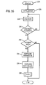
- microprocessor 48 monitors the back EMF voltages, block 176. If a voltage drop V AD , V BC or V CD is detected across thyristor switches 42, 44 or 46, respectively, a bypass contactor 50, 52 or 54, respectively has opened. By sensing the existence of a voltage V AD , V BC or V CD , across corresponding thyristor switch 42, 44 or 46, respectively, microprocessor 48 determines which contactor 50, 52 or 54 is opened, block 180.
- microprocessor 48 Immediately upon sensing the voltage drop, microprocessor 48 transmits a signal S A , S B or S C to fire the thyristor switch 42, 44 and/or 46, respectively, corresponding to the open bypass contactor 50, 52 or 54, respectively, block 182. Thereafter, microprocessor 48 transmits a signal B A , B B or B C to corresponding open bypass contactor 50, 52, or 54, respectively, attempting to reclose the open bypass contactor, block 184. If the open bypass contactor 50, 52, or 54 closes, block 186, AC induction motor 16 continues to rotate at full operating speed and microprocessor 48 returns to monitoring the back EMF voltage, block 176, in an attempt to determine if one of the bypass contactors opens.
- microprocessor 48 continues to fire the thyristor switch 42, 44, or 46 corresponding to the open bypass contactor 50, 52 or 54 in an attempt to reclose the same. If the open bypass contactor 50, 52 or 54 cannot be closed within a predetermined period of time, AC induction motor 16 is stopped, block 137.
- microprocessor 48 in order to stop AC induction motor 16 in response to a user command or a predetermined condition as heretofore described, microprocessor 48 initially determines whether the bypass contactors 50, 52 and 54 are closed, block 190, by sensing the existence of voltage drops V AD , V BD , and V CD across thyristor switches 42, 44 and 46, respectively. If bypass contactors 50, 52 and 54 are closed, microprocessor 48 transmits signals B A , B B and B C to open bypass contactors 50, 52 and 54, respectively, block 192, such that as soon as bypass contactors 50, 52 and 54 open, voltage drops V AD , V BD , and V CD are detected by microprocessor 48.
- microprocessor 48 immediately transmits signals S A , S B and S C to fire the thyristor switches 42, 44 and 46, respectively.
- AC induction motor 16 is gradually decelerated by opening notch ⁇ in supply voltages V A , V B and V C over a user selected period of time t3.
- block 196 such that no current or voltage is applied to AC induction motor 16.
- AC induction motor 16 stops under its load.
- microprocessor 48 of AC induction motor 16 to communicate with the other motor controls interconnected to the network for transmitting and receiving packets of information for reason hereinafter described.
- Microprocessor 48 periodically transmits output signals T XEN and T X onto the network through transceiver 63 and loads inputs signal R X received by transceiver 63 from the other motor control interconnected to the network, block 198.
- user input and display unit 22 includes a micro-controller 200 interconnected to an LCD display 210. It is contemplated that LCD display 210 be a standard four line by ten character display. User display input and display unit 22 further includes a serial EEPROM 212 interconnected to micro-controller 200 and a plurality of user input devices generally designated by the reference number 214. In the preferred embodiment, seen in Fig. 16, user input devices 214 include a shaft encoder 216 and four pushbutton switches 218-221.
- Micro-controller 200 is interconnected to the network by a transceiver 222. It is contemplated that transceiver 222 be a universal asynchronous receiver/transmitter such as a standard RS485 transceiver which allows micro-controller 200 to send and receive packets of information.
- transceiver 222 be a universal asynchronous receiver/transmitter such as a standard RS485 transceiver which allows micro-controller 200 to send and receive packets of information.
- micro-controller 200 initializes the items interconnected thereto and begins a discovery process, block 228, in order to transmit its identity to the other motor controls interconnected to the network and to discover the other motor controls interconnected to the network.
- Micro-controller 200 transmits a discovery signal onto the network through transceiver 222 and awaits a reply from the other motor controls. Thereafter, micro-controller 200 awaits until discovery is successful, block 230. If discovery is not successful, the process is repeated. However, if discovery is successful, micro-controller 200 will send a request for a parameter structure, block 232 from the predominant peer motor drive, e. g. self-starter 14, of motor control system 10.
- the parameter structure is a list of information defining software usage of a single motor drive parameter.
- the executable instructions on micro-controller 200 will end since there was no database match, block 232. However, if the database is matched, then the parameter structure information will be downloaded, block 234, by micro-controller 200 and stored in the serial EEPROM 212. Once the parameter structure information has been successfully downloaded, the data values associated with these parameters are also downloaded, block 236, and stored in RAM. After these steps have been completed, the executable instructions of micro-controller 200 vector to the Main subroutine.
- micro-controller 200 scans the input devices (shaft encoder 216 and pushbuttons 218-221) to determine if any user action has taken place, block 240. If a change is detected, block 242, micro-controller 200 executes the micro-controller executable instructions associated with each input device, Figs. 17-21.
- the Enter/Menu subroutine, block 243 is initiated by a user depressing the "enter/menu" pushbutton 219.
- the display on LCD display 210 is toggled between a main menu screen 246 and a parameter screen 248.
- the main menu screen 246 is displayed until the enter/menu pushbutton 219 is depressed.
- three parameters 250a, 250b and 250c are displayed.
- Arrow heads 252 are directed toward the middle displayed parameter 250b.
- the lower right hand corner of the main menu screen displays the word "enter," while the lower left hand comer of the screen displays the direction of AC induction motor 16.
- micro-controller 200 will perform the Increment/Decrement subroutine, block 251.
- the Increment/Decrement subroutine Fig. 19, if LCD is displaying the main menu screen, block 265, and shaft encoder 216 is rotated, the main menu screen 246 will scroll through the list of parameters stored in serial EEPROM 212, block 267.
- the LCD display 210 By depressing enter/menu pushbutton 219, the LCD display 210 will toggle to the parameter screen corresponding to the parameter 250b aligned with arrow heads 252.
- the top line 260 of the LCD display 210 displays a horizontal bar graph corresponding to the present value of parameter 248.
- the second line 262 displays the data value and the associated scale label of selected parameter 250b stored in the RAM.
- the third line displays the name of selected parameter 250b.
- the fourth line 264 will still display the motor direction in the lower left hand comer of LCD display 210, but the lower right hand comer will now read "main" since the new function of enter/menu 219 is to return the LCD display 210 to the main menu screen 246.
- the parameter data value shown on the second line 262 of the parameter screen 248 can be of two types, "changeable” or "meter” data values. If LCD display is displaying the parameter screen 248, block 265, and shaft encoder 216 is rotated, a user may modify the meter value of the displayed data value only if the data value is a "changeable” value, block 269. If the data value is not a "changeable” value, rotation of shaft encoder 216 will have no effect. If the data value is changed by the user, block 271, micro-controller 200 will transmit the user adjusted data value to microprocessor 48 of soft starter 14 upon the subsequent depression of enter/menu pushbutton 219 to toggle back to main menu screen 246. Thereafter, micro-controller 200 returns to the Main subroutine, block 273.
- micro-controller 200 upon depression of enter/menu pushbutton 219 to select a parameter 250b from main menu screen 246, micro-controller 200 sends a request through transceiver 222 over the network to the microprocessor 48 of the predominant peer motor control, self-starter 14, for the present value of the selected parameter 250b, which microprocessor 48 transmits back thereto.
- start pushbutton 220 work in conjunction with the motor direction pushbutton 218. Depression of motor direction pushbutton 218 by a user causes the lower left hand corner of LCD display 210 to toggle through a series of predetermined directional settings, e.g. forward, reverse, forward-jog, reverse-jog for AC induction motor 16, block 266. Referring Fig. 20, when the direction setting is in forward or reverse mode, the depression of the start pushbutton 220 causes micro-controller 200 to enter the Start subroutine, block 268, and send a command signal to the predominant motor control, self-starter 14, to start or stop AC induction motor 16, block 270, as heretofore described, in the user selected.
- start pushbutton 220 work in conjunction with the motor direction pushbutton 218. Depression of motor direction pushbutton 218 by a user causes the lower left hand corner of LCD display 210 to toggle through a series of predetermined directional settings, e.g. forward, reverse, forward-jog, reverse-jog for AC induction motor 16, block 2
- micro-controller 200 transmits a command signal, block 276, over the network to the predominant motor control, self-starter 14, upon release of the start pushbutton 220, block 274, to jog AC induction motor 16 in the user selected direction. Thereafter, the Start subroutine is ended, block 275.
- the micro-controller 200 upon depression of the stop pushbutton 221, the micro-controller 200 enters the Stop subroutine, block 276, and immediately sends a stop command, block 278, to the predominant motor control, soft starter 14, to stop AC induction motor 16.
- micro-controller 200 Upon release of stop pushbutton 220, block 279, micro-controller 200 sends a stop release command, block 281, to the predominant motor control, soft starter 14.
- the stop release command prevents soft starter 14 from being restarted until stop pushbutton 221 is released, regardless of whether or not a start command is received by microprocessor 48 at input 68b, or from another motor control on the network. Thereafter, the Stop subroutine ends, block 283.
- micro-controller updates the LCD display 210, block 285, and returns to the step of scanning the input devices thereto.
- motor control system 10 may include a programmable input/output module 26 having a micro-controller 280 interconnected to the network through transceiver 282.
- transceiver 282 be a universal asynchronous receiver/transmitter such as a standard RS485 transceiver.
- Transceiver 282 allows micro-controller 280 to transmit and receive signals from the other motor controls over the network.
- Programmable input/output module 26 further includes a plurality of user input/output devices generally designated by the reference number 284 and a plurality of LED's generally designated by the reference number 286 which are also interconnected to a micro-controller 280.
- the plurality of user input/output devices includes a first dip switch 290 movable between a first jam-on position and a second disabled position.
- micro-controller 280 transmits a control signal to microprocessor 48 of soft starter 14 over the network which instructs microprocessor 48 to monitor whether a jam condition is present on AC induction motor 16, as heretofore described.
- micro-controller 280 transmits a control signal to microprocessor 48 of soft starter 14 instructing microprocessor 48 to disable the microprocessor's 48 monitoring of a potential jam condition on AC induction motor 16.
- microprocessor 48 of soft starter 14 will transmit an alarm signal to micro-controller 280 of programmable input/output module 26 over the network such that micro-controller 280 of programmable input/output module 26 enables and illuminates LED 292.
- a second dip switch 294 is movable between a first stall-on position and a second disabled position.
- micro-controller 280 transmits a control signal to microprocessor 48 of soft starter 14 over the network which instructs microprocessor 48 to monitor whether a stall condition is present on AC induction motor 16 as heretofore described.
- micro-controller 280 transmits a control signal to microprocessor 48 of soft starter 14 instructing microprocessor 48 to disable the microprocessor's 48 monitoring of a potential stall condition on AC induction motor 16.
- microprocessor 48 of soft starter 14 will transmit an alarm signal to micro-controller 280 of programmable input/output module 26 over the network such that micro-controller 280 of programmable input/output module 26 enables and illuminates LED 296.
- a third dip switch 298 is movable between a first phase reversal position and a second disabled position.
- micro-controller 280 transmits a control signal to microprocessor 48 of soft starter 14 over the network which instructs microprocessor 48 to monitor whether the phases on AC induction motor 16 are reversed, as heretofore described.
- micro-controller 280 transmits a control signal to microprocessor 248 of soft starter 14 instructing microprocessor 48 to disable the microprocessor's 48 monitoring of a potential phase reversal on AC induction motor 16.
- microprocessor 48 of soft starter 14 will transmit an alarm signal to micro-controller 280 of programmable input/output module 26 over the network such that micro-controller 280 of programmable input/output module 26 enables and illuminates LED 300.
- Dip switch 302 is movable between a first manual reset position and a second auto reset position.
- micro-controller 280 transmits an instruction signal to microprocessor 48 of soft starter 14 instructing microprocessor 48 not to attempt to restart AC induction motor 16 after AC induction motor 16 has been stopped due to an overload or a fault, as heretofore described.
- micro-controller 280 transmits an instructions signal to microprocessor 48 of soft starter 14 such that soft starter 14 automatically attempts to restart AC induction motor 16 after a predetermined period of time after an overload or fault on AC induction motor 16 is determined.
- Dip switch 304 is movable between a first normal start position and a second pump start position. With dip switch 304 in a normal start position, micro-controller 280 transmits an instruction signal to microprocessor 48 of soft starter 14 to perform a normal ramp start, block 120, of AC induction motor 16, as heretofore described, upon receipt of a start command. With dip switch 304 in the pump start position, micro-controller 280 transmits an instruction signal to microprocessor 48 of soft starter 14 to perform a pump start, block 122, of AC induction motor 16 upon receipt of a start command.
- Dip switch 306 is movable between a first ramp start position and a second current limit position. With dip switch 306 in the ramp start position, micro-controller 280 transmits an instruction signal over the network to microprocessor 48 of soft starter 14 enabling microprocessor 48 to perform a normal ramp start, block 120, or a pump start, block 122, of AC induction motor 16 in response to receipt of a start command. With dip switch 306 in the current limit position, micro-controller 280 transmits an instruction signal to microprocessor 48 of soft starter 14 instructing soft starter 14 to perform a constant current start, block 124, of AC induction motor 16, as heretofore described, in response to a start command.
- Programmable input/output module 26 further includes a plurality of potentiometers for varying various time periods and torque values during start up of motor 16.
- Potentiometer 320 allows the user to set the time period t1 for a kick start of AC induction motor 16 by soft starter 14. By rotating potentiometer 320, the voltage drop across potentiometer 320 is varied such that the magnitude of the voltage drop corresponds to a predetermined time period t1 for the kick start of AC induction motor 16.
- potentiometer 320 is rotatable between t1 valve zero (0) seconds whereby no kick start of AC induction motor 16 is performed by soft starter 14 and two (2) seconds.
- micro-controller 280 transmits an instruction signal to microprocessor 48 of soft starter 14 to perform a kick start for the selected time period t1, as heretofore described.
- Potentiometer 322 allows the user to set the maximum torque value T1 for the kick start of AC induction motor 16 by soft starter 14. By rotating potentiometer 322, the voltage drop across potentiometer 322 is varied, such that the magnitude of the voltage drops corresponds to the user selected maximum torque T1 for the kick start of AC induction motor 16.
- potentiometer 322 is rotatable between a first value corresponding to zero (0) torque whereby no kick start of AC induction motor 16 is performed by soft starter 14 and ninety percent (90%) of the full, direct online starting torque of the AC induction motor.
- micro-controller 280 transmits an instruction signal to microprocessor 48 over the network to perform a kick start ramping the torque generated by AC induction motor 16 to the user selected value T1.
- Potentiometer 324 allows the user to set the time period t2 for soft starter 14 to ramp AC induction motor 16 to full operating speed. By rotating potentiometer 324, the voltage drop across potentiometer 324 is varied such that the magnitude of the voltage drop corresponds to the user selected time period t2 for the ramping of AC induction motor 16 from an initial user selected torque value T2 to a torque value corresponding to the operating of AC induction motor 16 at full voltage.
- potentiometer 324 is rotatable between a value corresponding to a ramp time of .5 seconds and a value corresponding to a ramp time of one hundred eighty (180) seconds.
- micro-controller 280 transmits an instruction signal to microprocessor 48 advising microprocessor 48 of the user selected time period t2 for bringing AC induction motor 16 to its full operating speed.
- Potentiometer 326 allows the user to set the initial torque value T2 after the kick start of AC induction motor 16. By rotating potentiometer 326, the voltage drop across potentiometer 326 is varied such that the magnitude of the voltage drop corresponds to a predetermined initial torque T2 generated by AC induction motor 16 after the kick start thereof.
- potentiometer 326 is rotatable between a value corresponding to zero (0) torque whereby the motor 16 generates no torque after kick start, and a value corresponding to an initial torque of one hundred percent (100%) of the torque value provided by operating AC induction motor 16 at full supply voltage.
- micro-controller 280 transmits an instruction signal to microprocessor 48 such that the initial torque will equal the user selected initial torque T2.
- Potentiometer 328 allows the user to set the time period t3 for gradually increasing the duration of notch ⁇ during the stopping of AC induction motor 16, as heretofore described. By rotating potentiometer 328, the voltage drop across potentiometer 328 is varied such that the magnitude of the voltage drop thereacross corresponds to a user selected time period t3 for gradually stopping AC induction motor 16.
- potentiometer 328 is rotatable between a value corresponding to zero (0) seconds whereby the AC induction motor 16 is not gradually stopped and a value corresponding to sixty (60) seconds.
- micro-controller 280 transmits an instruction signal to microprocessor 48 to gradually stop AC induction motor 16 after the opening bypass contactor 50, 52 and 54 and prior to opening thyristor switches 42, 44 and 46 for a time period t3 in a manner heretofore described.
- Potentiometer 330 allows a user to advise microprocessor 48 of the full load ampere rating for AC induction motor 16. By rotating potentiometer 330, the voltage drop thereacross is varied such that the magnitude of the voltage drop corresponds to a predetermined full load ampere rating for AC induction motor 16. In response to setting of potentiometer 320 and the voltage drop thereacross, micro-controller 280 transmits an instruction signal to microprocessor 48 advising microprocessor 48 of the full load ampere rating of AC induction motor 16.
- Programmable input/output module 26 further includes first and second trip class dip switches 332 and 334, respectively. Each trip class dip switch 332 and 334 is movable between first and second positions. The combination of positions of trip class dip switches 332 and 334 allows a user to set the trip class for microprocessor 48 to monitor for a thermal overload on AC induction motor 16. In response to the combination of settings of trip class switches 332 and 334, micro-controller 280 transmits an instruction signal to microprocessor 48 instructing microprocessor 48 as to the desired trip class when determining if the thermal overload has occurred on AC induction motor 16. Programmable input/output module 26 further includes an LED 336 for signaling to a user that a thermal overload condition exists on AC induction motor 16.
- microprocessor 48 transmits an instruction signal to micro-controller 280 advising micro-controller 280 of the thermal overload condition.
- micro-controller 280 enables overload LED 336 so as to advise a user accordingly.
- Programmable input/output module 26 further includes a thermal overload LED 337.
- microprocessor 48 further monitors for a thermal overload condition, block 106, on AC induction motor 16. If microprocessor 48 detects a thermal overload condition on AC induction motor 16, microprocessor 48 of soft starter 14 will transmit an alarm signal to micro-controller 280 of programmable input/output module 26 over the network such that micro-controller 280 of programmable input/output module 26 enables and illuminates thermal overload LED 337.
- micro-controller 280 is initialized, block 342. Thereafter, micro-controller 280 begins the discovery process, block 344, in order to transmits its identity to the other motor controls interconnected to the network and to discover the other motor controls interconnected to the network. Micro-controller 280 transmits a discovery signal onto the network through transceiver 282 and awaits a reply from the other motor controls, block 346. If discovery is not successful, the process is repeated. However, if discovery is successful, micro-controller 280 performs the Main subroutine, block 347, of its computer executable instructions.
- a flow chart for the Main subroutine of the computer executable instructions stored on micro-controller 280 is provided.
- the micro-controller 280 scans the dip switches, block 348, and updates the jam LED 292, the stall LED 296, the phase reversal LED 300, the overload LED 336, and the thermal overload LED 337, block 350, in response to an instruction or alarm signal received from microprocessor 48 of soft starter 14.
- micro-controller 280 receives a request for data over the network from microprocessor 48 of soft starter 14, block 352, micro-controller 280 processes the request from microprocessor 48, block 354, scans the potentiometers, block 356, and transmits the requested information regarding the position of the potentiometers and dip switches, block 358, to micro-controller 48 of soft starter 14, as heretofore described.
- button module 28 includes a housing 360 for supporting a plurality of dip switches 362a-362h and a plurality of pushbutton switches 364a-364f.
- An overlay 366 is provided to overlay upper surface 368 of housing 360.
- Overlay 366 includes six button portions 370a-370f which overlap and correspond to pushbutton switches 364a-364f, respectively.
- pushbuttons 364a-364f and dip switches 362a-362h are generally designated by the reference numeral 372.
- Input devices 372 are interconnected to a micro-controller 374 which, in turn, is interconnected the network by transceiver 376.
- transceiver 376 be a universal asynchronous receiver/transmitter such as a standard RS485 transceiver.
- a plurality of LEDs 378a-378f may be interconnected to micro-controller 374 to indicate the status of a various motor parameters, as hereinafter described.
- LEDs 378a-378f correspond to and are position adjacent pushbuttons 364a-364f, respectively.
- each combination of settings of dip switches 362a-362h corresponds to a unique combination of assignments for pushbuttons 364a-364f and LEDs 378a-378f.
- micro-controller 374 will transmit different pre-programed instruction signals to the other motor controls of the motor control system 10 in response to the depression of pushbuttons 364a-364f and will enable different LEDs 378a-378f in response to receipt of a command from one of the other motor controls of the motor control system 10.
- overlays 366a-366c are provided. Each overlay corresponds to a different settings of the dip switches 362a-362h and hence, different assignments for pushbuttons 364a-364f and LEDs 378a - 378f.
- pushbuttons 364a, 364c and 364d are unassigned, and hence, button portions 370a, 370c and 370d of overlay 366 are free of indicia.
- pushbutton 364b is also unassigned, but micro-controller 374 enables LED 378b if motor control system 10 is off.
- button portion 370b of overlay 366 has indicia indicating such an assignment.
- micro-controller 374 In response to depression of pushbutton 364e, micro-controller 374 transmits a start command to microprocessor 48 of soft starter 14. LED 378e is enabled by micro-controller 374 in response to depression of pushbutton 364e in order to alert a user to that the start command has been transmitted by micro-controller 374.
- Button portion 370e of overlay 366 is provided which indicia thereon identifying the function of pushbutton 364e.
- depression of pushbutton 364f causes the micro-controller 374 to transmit a stop command to microprocessor 48 of soft starter 14 in order to stop AC induction motor 16, as heretofore described.
- micro-controller 374 enables LED 378f in order to alert the user that the stop command has been transmitted by micro-controller 374.
- Button portion 370f of overlay 366 has indicia thereon to identify the function of pushbutton 364f.
- Figs. 27b and 27c correspond to various alternate assignments for pushbuttons 364a-364f and for LEDs 378a-378f based on the combination of settings of dip switches 362a-362h.
- the indicia on button portions 370a-370f correspond to the assignments of pushbuttons 364a-364f and LEDs 378a-378f.
- Figs. 27a-27c are provided as sample representations of the assignments for pushbuttons 364a-364f and LEDs 378a-378f, and are not intended to be limiting as to the possible assignments of pushbuttons 368a-368f and LEDs 378a-378f based upon the combination of settings of dip switches 362a-362h.
- micro-controller 374 is initialized, block 380.
- the banks of RAM of the micro-controller 374 are cleared; the input and output ports of micro-controller 374 and their data direction registers are set; and the communication variables and clock registers are initialized.
- micro-controller 374 After initialization, micro-controller 374 begins a discovery process, block 382, in order to transmit its identity to the other motor controls interconnected to the network and discover the other motor controls interconnected to the network. Micro-controller 374 transmits a discovery signal onto the network through transceiver 376 until such time that micro-controller 374 receives a response from each of the other motor controls interconnected to the network, block 384.
- micro-controller 374 While waiting for a response from the other motor controls interconnected to the network, micro-controller 374 will, at predetermined time intervals, block 386, scan pushbuttons 364a-364f to determine if one of the pushbuttons 364a-364f has been depressed. It is contemplated that micro-controller 374 may detect a stuck pushbutton 364a-364f if micro-controller 374 senses that a pushbutton 364a-364f is depressed for more than a predetermined number of consecutive scans.
- micro-controller 374 determines if such instruction signal requires enabling an LED 378a-378f. In response to receipt of such an instruction signal received from a peer motor control interconnected to the network, micro-controller 374 updates or enables the corresponding LED 378a-378f, block 392, as heretofore described.
- micro-controller 374 If micro-controller 374 is properly connected to the network through transceiver 376, block 394, and if one of the pushbuttons 364a-364f has been validly depressed, block 396, micro-controller 374 transmits an instruction signal to the appropriate motor control on the network, block 398, based upon the settings of dip switches 362a-362h so as to perform the user desired command. Similarly, if micro-controller 374 receives a valid signal from one of the other motor controls, block 400, interconnected to the network, the micro-controller 374 processes the received signal and interprets the same, block 402, to perform the command.
- Micro-controller 374 also may receive a discovery signal from one of the other motor controls interconnected to the network, block 404. If the micro-controller 374 is properly connected to the network by transceiver 376, block 406, micro-controller 374 transmits a response identifying itself to the corresponding motor control which transmitted the discovery signal, block 408.
Landscapes
- Engineering & Computer Science (AREA)
- Power Engineering (AREA)
- Motor And Converter Starters (AREA)
- Control Of Ac Motors In General (AREA)
Applications Claiming Priority (2)
| Application Number | Priority Date | Filing Date | Title |
|---|---|---|---|
| US266549 | 1999-03-11 | ||
| US09/266,549 US6163129A (en) | 1999-03-11 | 1999-03-11 | Method of controlling the starting, stopping and speed of an AC induction motor |
Publications (3)
| Publication Number | Publication Date |
|---|---|
| EP1037372A2 true EP1037372A2 (de) | 2000-09-20 |
| EP1037372A3 EP1037372A3 (de) | 2002-08-28 |
| EP1037372B1 EP1037372B1 (de) | 2006-05-24 |
Family
ID=23015036
Family Applications (1)
| Application Number | Title | Priority Date | Filing Date |
|---|---|---|---|
| EP00301964A Expired - Lifetime EP1037372B1 (de) | 1999-03-11 | 2000-03-10 | Verfahren zur Regelung des Startens, des Anhaltens und der Geschwindigkeit eines Wechselstrominduktionsmotors |
Country Status (6)
| Country | Link |
|---|---|
| US (1) | US6163129A (de) |
| EP (1) | EP1037372B1 (de) |
| JP (1) | JP4605414B2 (de) |
| CN (1) | CN1214513C (de) |
| BR (1) | BR0000948A (de) |
| DE (1) | DE60028110T2 (de) |
Cited By (7)
| Publication number | Priority date | Publication date | Assignee | Title |
|---|---|---|---|---|
| EP1168590A1 (de) * | 2000-06-28 | 2002-01-02 | Siemens Energy & Automation, Inc. | Automatisches Erkennen der Überbrückung eines Motoranlassers oder einer Motorsteuerung |
| WO2001089074A3 (en) * | 2000-05-19 | 2002-03-28 | Eaton Corp | Method for controlling the starting of an ac induction motor with closed loop current control |
| EP1986316A1 (de) * | 2007-04-26 | 2008-10-29 | Siemens Aktiengesellschaft | Entlastung des Bypasssystems von Sanftanlaufgeräten von Überströmen |
| FR2980315A1 (fr) * | 2011-09-21 | 2013-03-22 | Alstom Grid Sas | Procede d'ouverture d'interrupteur de derivation de reseau a courant continu haute tension |
| RU2510125C1 (ru) * | 2012-08-14 | 2014-03-20 | Юрий Иванович Доломанов | Устройство для управления пуском и остановом асинхронного электродвигателя |
| WO2016030098A1 (de) * | 2014-08-26 | 2016-03-03 | Ebm-Papst Mulfingen Gmbh & Co. Kg | Elektrischer antrieb |
| EP2293426B1 (de) * | 2009-09-02 | 2016-04-27 | Carlo Gavazzi Services AG | Soft Starter Vorrichtung und Verfahren für einen Elektromotor |
Families Citing this family (45)
| Publication number | Priority date | Publication date | Assignee | Title |
|---|---|---|---|---|
| US6445966B1 (en) * | 1999-03-11 | 2002-09-03 | Eaton Corporation | Data interface module for motor control system |
| US6529785B1 (en) * | 1999-09-27 | 2003-03-04 | Rockwell Automation Technologies, Inc. | Jog control for industrial control network |
| US6701462B1 (en) | 2000-05-19 | 2004-03-02 | Rockwell Automation Technologies, Inc. | Situational aware output configuration and execution |
| US6591311B1 (en) | 2000-04-27 | 2003-07-08 | Rockwell Automation Technologies, Inc. | Method and system for selecting controller output value source |
| US6745232B1 (en) | 2000-08-23 | 2004-06-01 | Rockwell Automation Technologies, Inc. | Strobed synchronization providing diagnostics in a distributed system |
| US6701214B1 (en) | 2000-04-27 | 2004-03-02 | Rockwell Automation Technologies, Inc. | Driver board control system for modular conveyer with address-based network for inter-conveyor communication |
| US6380708B1 (en) * | 2000-05-19 | 2002-04-30 | Eaton Corporation | Method for controlling the starting of an AC induction motor |
| US6407529B1 (en) * | 2000-05-19 | 2002-06-18 | Eaton Corporation | Method for controlling the starting of an induction motor utilizing closed loop alpha control |
| JP3775416B2 (ja) * | 2003-02-10 | 2006-05-17 | オムロン株式会社 | インバータ装置 |
| US7196491B2 (en) * | 2003-02-12 | 2007-03-27 | Siemens Energy & Automation, Inc. | System and method for stall detection of a motor |
| US7602128B2 (en) * | 2003-03-03 | 2009-10-13 | Abb Ab | Device and method to configure same |
| DE102004030130A1 (de) * | 2004-06-22 | 2006-01-19 | Robert Bosch Gmbh | Verfahren und Vorrichtung zur Blockiererkennung eines Gleichstrommotors |
| US7821220B2 (en) | 2006-09-29 | 2010-10-26 | Rockwell Automation Technologies, Inc. | Motor having integral programmable logic controller |
| US7440261B2 (en) * | 2006-10-19 | 2008-10-21 | Saul Lin | Power regulator with a bypass and splice capability |
| US7633260B2 (en) | 2007-10-31 | 2009-12-15 | Hilton Raymond Bacon | Apparatus and method for starting and stopping an AC induction motor |
| US8089735B2 (en) * | 2008-12-01 | 2012-01-03 | Custom Sensors & Technologies, Inc. | Hybrid power relay with thermal protection |
| US8084984B2 (en) * | 2008-12-22 | 2011-12-27 | Eaton Corporation | System and method for monitoring and controlling stator winding temperature in a de-energized AC motor |
| CN102301253B (zh) * | 2009-01-28 | 2014-08-13 | 大陆汽车有限责任公司 | 用于运行无刷电动机的方法 |
| DE102009007522B4 (de) * | 2009-02-05 | 2011-09-01 | Siemens Aktiengesellschaft | Steuerschaltung für einen Drehstromasynchronmotor |
| DE102011009689B4 (de) * | 2010-02-25 | 2012-09-13 | Sms Meer Gmbh | Strangpresse zum Herstellen von Profilen aus Nichteisenmetall |
| US8638059B2 (en) | 2010-08-11 | 2014-01-28 | Dayton-Phoenix Group, Inc. | Control for multi-phase induction motor |
| US8587240B2 (en) * | 2011-07-20 | 2013-11-19 | Eaton Corporation | Operationally dependent filtering for soft starter current measurements |
| DE102011081766A1 (de) * | 2011-08-30 | 2013-02-28 | Siemens Aktiengesellschaft | Netzüberwachungsvorrichtung |
| GB201200803D0 (en) * | 2012-01-18 | 2012-02-29 | Rolls Royce Goodrich Engine Control Systems Ltd | Fault tolerant electric drive system |
| DE102012205708A1 (de) * | 2012-04-05 | 2013-10-10 | Lenze Automation Gmbh | Verfahren zum Betreiben eines elektrischen Antriebssystems und Antriebssystem |
| CN104603899B (zh) * | 2012-08-30 | 2017-06-13 | 西门子公司 | 用于控制连接在下游的电机的能量供给的开关设备 |
| EP2898521B2 (de) * | 2012-11-19 | 2021-10-13 | Siemens Aktiengesellschaft | Schaltgerät zum steuern der energiezufuhr eines nachgeschalteten elektromotors |
| US9559628B2 (en) | 2013-10-25 | 2017-01-31 | Black & Decker Inc. | Handheld power tool with compact AC switch |
| RU2544004C1 (ru) * | 2013-11-28 | 2015-03-10 | Федеральное государственное бюджетное образовательное учреждение высшего профессионального образования "Кузбасский государственный технический университет имени Т.Ф. Горбачева" (КузГТУ) | Способ позиционирования асинхронного электропривода |
| US9160257B2 (en) * | 2013-12-23 | 2015-10-13 | Eaton Corporation | Soft starter system and method of operating same |
| US20170033720A1 (en) * | 2014-04-25 | 2017-02-02 | Kmt Waterjet System Inc. | Control system for an induction motor |
| US20160173008A1 (en) * | 2014-12-11 | 2016-06-16 | Solcon Industries Ltd. | System and method for soft starting and stopping of a motor |
| US9903060B2 (en) | 2015-01-13 | 2018-02-27 | Haier Us Appliance Solutions, Inc. | Induction motor temperature measurement using phase controlled alternating current |
| CN105991080B (zh) * | 2015-02-26 | 2021-09-10 | 伊顿智能动力有限公司 | 一种用于电机和供电网的连接装置 |
| CN105227000A (zh) * | 2015-09-15 | 2016-01-06 | 苏州艾克威尔科技有限公司 | 一种内置单相旁路的电机启动装置 |
| US9800188B2 (en) * | 2015-09-15 | 2017-10-24 | Regal Beloit America, Inc. | Hybrid drive circuit for variable speed induction motor |
| CN105226928A (zh) * | 2015-10-29 | 2016-01-06 | 佛山市和融数控软件有限公司 | 一种陶机设备上防止交流输入过压的软启动电路 |
| CN105811810A (zh) * | 2016-05-09 | 2016-07-27 | 李堂兴 | 风机软启动控制装置 |
| CN105871258A (zh) * | 2016-05-09 | 2016-08-17 | 李堂兴 | 风机软启动控制线路 |
| US10819254B2 (en) * | 2017-03-20 | 2020-10-27 | Regal Beloit America, Inc. | Drive circuit for electric motors |
| US11139649B2 (en) | 2017-12-26 | 2021-10-05 | Eaton Intelligent Power Limited | Motor control system with integrated solid-state contactor and relays and method of operation thereof |
| US10594246B2 (en) | 2017-12-26 | 2020-03-17 | Eaton Intelligent Power Limited | Board-level motor control system with integrated protection and control components |
| CN109510513A (zh) * | 2018-07-18 | 2019-03-22 | 上海锐机电有限公司 | 一种侧推大功设备软启动系统 |
| US11557979B2 (en) | 2018-11-14 | 2023-01-17 | Eaton Intelligent Power Limited | Variable frequency drive with integrated front-end rectifier and bypass |
| US11251741B2 (en) | 2018-11-15 | 2022-02-15 | Eaton Intelligent Power Limited | Modular board-level motor control system with integrated protection and control components |
Citations (7)
| Publication number | Priority date | Publication date | Assignee | Title |
|---|---|---|---|---|
| US4142136A (en) * | 1977-04-08 | 1979-02-27 | Mollenberg-Betz Machine Company | Control circuit for starting a motor |
| EP0149873A2 (de) * | 1984-01-23 | 1985-07-31 | LOUIS BARRERE et Cie S.A. | Anlaufvorrichtung für einen asynchronen Elektromotor |
| US4767975A (en) * | 1983-09-15 | 1988-08-30 | National Research Development Corporation | Controller for induction motors |
| JPH01316021A (ja) * | 1989-02-08 | 1989-12-20 | Fuji Electric Co Ltd | 無接点接触器 |
| EP0435038A2 (de) * | 1989-12-26 | 1991-07-03 | Allen-Bradley Company, Inc. | Regler für das Starten und Anhalten von elektrischen Motoren |
| EP0446936A2 (de) * | 1990-03-16 | 1991-09-18 | Allen-Bradley Company, Inc. | Steuergerät für einen Elektromotor mit Überbrückungsschaltschütz |
| US5859514A (en) * | 1995-05-05 | 1999-01-12 | Schneider Electric Sa | Control method for a start-up control unit and an apparatus to make use of this method |
Family Cites Families (10)
| Publication number | Priority date | Publication date | Assignee | Title |
|---|---|---|---|---|
| US3991354A (en) * | 1975-05-29 | 1976-11-09 | Westinghouse Electric Corporation | Variable speed drive for induction motor |
| US4426614A (en) * | 1981-11-30 | 1984-01-17 | The United States Of America As Represented By The Administrator Of The National Aeronautics And Space Administration | Pulsed thyristor trigger control circuit |
| US4712054A (en) * | 1986-05-14 | 1987-12-08 | East Moline Metal Products Company | Controller with two modes of braking induction motors |
| US4796142A (en) * | 1986-10-16 | 1989-01-03 | Square D Company | Overload protection apparatus for emulating the response of a thermal overload |
| JPS63204307A (ja) * | 1987-02-19 | 1988-08-24 | Fanuc Ltd | 過電流検出装置 |
| US5305234A (en) * | 1991-12-31 | 1994-04-19 | Westinghouse Electric Corp. | Thermal protection apparatus for a synchronous machine |
| JPH0654568A (ja) * | 1992-06-05 | 1994-02-25 | Toshio Furukawa | 3相誘導電動機の始動制御装置 |
| JPH0746871A (ja) * | 1993-07-28 | 1995-02-14 | Matsushita Electric Works Ltd | 交流電動機等の駆動回路 |
| JPH10201194A (ja) * | 1997-01-16 | 1998-07-31 | Mitsubishi Heavy Ind Ltd | エアクールコンデンサ |
| JPH10337063A (ja) * | 1997-06-05 | 1998-12-18 | Hirohito Sato | 交流電動機の始動方法及び装置 |
-
1999
- 1999-03-11 US US09/266,549 patent/US6163129A/en not_active Expired - Lifetime
-
2000
- 2000-03-10 CN CN00104002.2A patent/CN1214513C/zh not_active Expired - Fee Related
- 2000-03-10 EP EP00301964A patent/EP1037372B1/de not_active Expired - Lifetime
- 2000-03-10 DE DE60028110T patent/DE60028110T2/de not_active Expired - Lifetime
- 2000-03-10 BR BR0000948-2A patent/BR0000948A/pt not_active Application Discontinuation
- 2000-03-13 JP JP2000069347A patent/JP4605414B2/ja not_active Expired - Fee Related
Patent Citations (7)
| Publication number | Priority date | Publication date | Assignee | Title |
|---|---|---|---|---|
| US4142136A (en) * | 1977-04-08 | 1979-02-27 | Mollenberg-Betz Machine Company | Control circuit for starting a motor |
| US4767975A (en) * | 1983-09-15 | 1988-08-30 | National Research Development Corporation | Controller for induction motors |
| EP0149873A2 (de) * | 1984-01-23 | 1985-07-31 | LOUIS BARRERE et Cie S.A. | Anlaufvorrichtung für einen asynchronen Elektromotor |
| JPH01316021A (ja) * | 1989-02-08 | 1989-12-20 | Fuji Electric Co Ltd | 無接点接触器 |
| EP0435038A2 (de) * | 1989-12-26 | 1991-07-03 | Allen-Bradley Company, Inc. | Regler für das Starten und Anhalten von elektrischen Motoren |
| EP0446936A2 (de) * | 1990-03-16 | 1991-09-18 | Allen-Bradley Company, Inc. | Steuergerät für einen Elektromotor mit Überbrückungsschaltschütz |
| US5859514A (en) * | 1995-05-05 | 1999-01-12 | Schneider Electric Sa | Control method for a start-up control unit and an apparatus to make use of this method |
Non-Patent Citations (1)
| Title |
|---|
| PATENT ABSTRACTS OF JAPAN vol. 014, no. 120 (E-0899), 6 March 1990 (1990-03-06) & JP 01 316021 A (FUJI ELECTRIC CO LTD), 20 December 1989 (1989-12-20) * |
Cited By (10)
| Publication number | Priority date | Publication date | Assignee | Title |
|---|---|---|---|---|
| WO2001089074A3 (en) * | 2000-05-19 | 2002-03-28 | Eaton Corp | Method for controlling the starting of an ac induction motor with closed loop current control |
| EP1168590A1 (de) * | 2000-06-28 | 2002-01-02 | Siemens Energy & Automation, Inc. | Automatisches Erkennen der Überbrückung eines Motoranlassers oder einer Motorsteuerung |
| US6586905B1 (en) | 2000-06-28 | 2003-07-01 | Siemens Energy & Automation | Automatic sensing of bypassing of soft starter or controller |
| EP1986316A1 (de) * | 2007-04-26 | 2008-10-29 | Siemens Aktiengesellschaft | Entlastung des Bypasssystems von Sanftanlaufgeräten von Überströmen |
| EP2293426B1 (de) * | 2009-09-02 | 2016-04-27 | Carlo Gavazzi Services AG | Soft Starter Vorrichtung und Verfahren für einen Elektromotor |
| FR2980315A1 (fr) * | 2011-09-21 | 2013-03-22 | Alstom Grid Sas | Procede d'ouverture d'interrupteur de derivation de reseau a courant continu haute tension |
| WO2013041614A3 (fr) * | 2011-09-21 | 2013-08-29 | Alstom Technology Ltd | Procede d'ouverture d'interrupteur de derivation de reseau a courant continu haute tension |
| US9094009B2 (en) | 2011-09-21 | 2015-07-28 | Alstom Technology Ltd. | Method of opening a bypass switch of a high voltage direct current network |
| RU2510125C1 (ru) * | 2012-08-14 | 2014-03-20 | Юрий Иванович Доломанов | Устройство для управления пуском и остановом асинхронного электродвигателя |
| WO2016030098A1 (de) * | 2014-08-26 | 2016-03-03 | Ebm-Papst Mulfingen Gmbh & Co. Kg | Elektrischer antrieb |
Also Published As
| Publication number | Publication date |
|---|---|
| JP4605414B2 (ja) | 2011-01-05 |
| EP1037372A3 (de) | 2002-08-28 |
| CN1214513C (zh) | 2005-08-10 |
| JP2000278991A (ja) | 2000-10-06 |
| BR0000948A (pt) | 2000-10-10 |
| DE60028110T2 (de) | 2006-12-21 |
| DE60028110D1 (de) | 2006-06-29 |
| US6163129A (en) | 2000-12-19 |
| EP1037372B1 (de) | 2006-05-24 |
| CN1267127A (zh) | 2000-09-20 |
Similar Documents
| Publication | Publication Date | Title |
|---|---|---|
| US6163129A (en) | Method of controlling the starting, stopping and speed of an AC induction motor | |
| EP1037374B1 (de) | Interfacemodul für ein Motorsteuerungssystem | |
| EP1037375B1 (de) | Dateninterfacemodul für ein Motorsteuerungssystem | |
| EP1037373B1 (de) | Regelungsmodul für ein Motorsteuerungssystem | |
| US7859217B2 (en) | System and method for operating a soft starter in conjunction with a single to three phase static converter | |
| JPH01209969A (ja) | 交流電動機の始動制御回路および交流電動機の始動巻線を制御する方法 | |
| CA2008688C (en) | Method and apparatus for detecting deviation of motor speed from frequency of power supply | |
| JP3201525B2 (ja) | インバータ給電式篭形誘導機の残留磁束決定方法 | |
| KR100451369B1 (ko) | 유도 전동기의 회전 속도 검출 방법 | |
| US5444350A (en) | Process for determining the load of an asynchronous motor fed via a frequency converter and a device for carrying out the process | |
| EP1027759B1 (de) | Lastanzeiger | |
| US11456683B2 (en) | Method for a network synchronization of a permanently excited three-phase machine comprising a soft starter which comprises thyristors | |
| CA2268251C (en) | Three-phase power controller with interrupt-controlled phase-gating control | |
| KR100307999B1 (ko) | 유도 전동기 제어 방법 및 그 장치 | |
| JP3129562B2 (ja) | 誘導電動機の速度制御装置 | |
| SU748765A1 (ru) | Устройство дл управлени асинхронным электроприводом | |
| JPH02211079A (ja) | ヒステリシス電動機の運転制御装置 | |
| JPH0382381A (ja) | クレーン制御方法 | |
| JPH07123774A (ja) | 位置センサレスdcブラシレスモータの制御装置 | |
| JPH01202678A (ja) | 電動機のストール検出方法 | |
| KR20040076378A (ko) | 하이브리드 모터 스타터의 정지 제어회로 | |
| JPH01110496A (ja) | グラブバケットの巻上方法及びその装置 | |
| JPH06165394A (ja) | 発電電動機系統並入制御装置 | |
| JPH0717345B2 (ja) | 可変速巻上機 | |
| JPH10112930A (ja) | 開閉体の駆動制御装置 |
Legal Events
| Date | Code | Title | Description |
|---|---|---|---|
| PUAI | Public reference made under article 153(3) epc to a published international application that has entered the european phase |
Free format text: ORIGINAL CODE: 0009012 |
|
| AK | Designated contracting states |
Kind code of ref document: A2 Designated state(s): AT BE CH CY DE DK ES FI FR GB GR IE IT LI LU MC NL PT SE |
|
| AX | Request for extension of the european patent |
Free format text: AL;LT;LV;MK;RO;SI |
|
| PUAL | Search report despatched |
Free format text: ORIGINAL CODE: 0009013 |
|
| AK | Designated contracting states |
Kind code of ref document: A3 Designated state(s): AT BE CH CY DE DK ES FI FR GB GR IE IT LI LU MC NL PT SE |
|
| AX | Request for extension of the european patent |
Free format text: AL;LT;LV;MK;RO;SI |
|
| RIC1 | Information provided on ipc code assigned before grant |
Free format text: 7H 02P 7/62 A, 7H 02P 1/26 B, 7H 02P 3/18 B, 7H 02P 7/622 B, 7G 05B 19/10 B |
|
| 17P | Request for examination filed |
Effective date: 20030114 |
|
| AKX | Designation fees paid |
Designated state(s): DE FR GB |
|
| 17Q | First examination report despatched |
Effective date: 20040220 |
|
| GRAP | Despatch of communication of intention to grant a patent |
Free format text: ORIGINAL CODE: EPIDOSNIGR1 |
|
| GRAS | Grant fee paid |
Free format text: ORIGINAL CODE: EPIDOSNIGR3 |
|
| GRAA | (expected) grant |
Free format text: ORIGINAL CODE: 0009210 |
|
| RIC1 | Information provided on ipc code assigned before grant |
Ipc: G05B 19/10 20060101ALI20060330BHEP Ipc: H02P 3/18 20060101ALI20060330BHEP Ipc: H02P 27/02 20060101ALI20060330BHEP Ipc: H02P 23/00 20060101AFI20060330BHEP Ipc: H02P 1/26 20060101ALI20060330BHEP |
|
| AK | Designated contracting states |
Kind code of ref document: B1 Designated state(s): DE FR GB |
|
| REG | Reference to a national code |
Ref country code: GB Ref legal event code: FG4D |
|
| REF | Corresponds to: |
Ref document number: 60028110 Country of ref document: DE Date of ref document: 20060629 Kind code of ref document: P |
|
| ET | Fr: translation filed | ||
| PLBE | No opposition filed within time limit |
Free format text: ORIGINAL CODE: 0009261 |
|
| STAA | Information on the status of an ep patent application or granted ep patent |
Free format text: STATUS: NO OPPOSITION FILED WITHIN TIME LIMIT |
|
| 26N | No opposition filed |
Effective date: 20070227 |
|
| REG | Reference to a national code |
Ref country code: FR Ref legal event code: PLFP Year of fee payment: 17 |
|
| REG | Reference to a national code |
Ref country code: FR Ref legal event code: PLFP Year of fee payment: 18 |
|
| REG | Reference to a national code |
Ref country code: FR Ref legal event code: PLFP Year of fee payment: 19 |
|
| PGFP | Annual fee paid to national office [announced via postgrant information from national office to epo] |
Ref country code: DE Payment date: 20180219 Year of fee payment: 19 Ref country code: GB Payment date: 20180226 Year of fee payment: 19 |
|
| PGFP | Annual fee paid to national office [announced via postgrant information from national office to epo] |
Ref country code: FR Payment date: 20180220 Year of fee payment: 19 |
|
| REG | Reference to a national code |
Ref country code: GB Ref legal event code: 732E Free format text: REGISTERED BETWEEN 20181115 AND 20181130 |
|
| REG | Reference to a national code |
Ref country code: DE Ref legal event code: R082 Ref document number: 60028110 Country of ref document: DE Ref country code: DE Ref legal event code: R081 Ref document number: 60028110 Country of ref document: DE Owner name: EATON INTELLIGENT POWER LIMITED, IE Free format text: FORMER OWNER: EATON CORP., CLEVELAND, OHIO, US |
|
| REG | Reference to a national code |
Ref country code: DE Ref legal event code: R119 Ref document number: 60028110 Country of ref document: DE |
|
| GBPC | Gb: european patent ceased through non-payment of renewal fee |
Effective date: 20190310 |
|
| PG25 | Lapsed in a contracting state [announced via postgrant information from national office to epo] |
Ref country code: DE Free format text: LAPSE BECAUSE OF NON-PAYMENT OF DUE FEES Effective date: 20191001 Ref country code: GB Free format text: LAPSE BECAUSE OF NON-PAYMENT OF DUE FEES Effective date: 20190310 |
|
| PG25 | Lapsed in a contracting state [announced via postgrant information from national office to epo] |
Ref country code: FR Free format text: LAPSE BECAUSE OF NON-PAYMENT OF DUE FEES Effective date: 20190331 |