EP1036596B1 - Method for the decomposition and separation of recyclable three-material composite components by type - Google Patents
Method for the decomposition and separation of recyclable three-material composite components by type Download PDFInfo
- Publication number
- EP1036596B1 EP1036596B1 EP19990123677 EP99123677A EP1036596B1 EP 1036596 B1 EP1036596 B1 EP 1036596B1 EP 19990123677 EP19990123677 EP 19990123677 EP 99123677 A EP99123677 A EP 99123677A EP 1036596 B1 EP1036596 B1 EP 1036596B1
- Authority
- EP
- European Patent Office
- Prior art keywords
- sorting
- fraction
- separated
- sieve
- particles
- Prior art date
- Legal status (The legal status is an assumption and is not a legal conclusion. Google has not performed a legal analysis and makes no representation as to the accuracy of the status listed.)
- Expired - Lifetime
Links
Images


Classifications
-
- B—PERFORMING OPERATIONS; TRANSPORTING
- B29—WORKING OF PLASTICS; WORKING OF SUBSTANCES IN A PLASTIC STATE IN GENERAL
- B29B—PREPARATION OR PRETREATMENT OF THE MATERIAL TO BE SHAPED; MAKING GRANULES OR PREFORMS; RECOVERY OF PLASTICS OR OTHER CONSTITUENTS OF WASTE MATERIAL CONTAINING PLASTICS
- B29B17/00—Recovery of plastics or other constituents of waste material containing plastics
- B29B17/02—Separating plastics from other materials
-
- B—PERFORMING OPERATIONS; TRANSPORTING
- B03—SEPARATION OF SOLID MATERIALS USING LIQUIDS OR USING PNEUMATIC TABLES OR JIGS; MAGNETIC OR ELECTROSTATIC SEPARATION OF SOLID MATERIALS FROM SOLID MATERIALS OR FLUIDS; SEPARATION BY HIGH-VOLTAGE ELECTRIC FIELDS
- B03B—SEPARATING SOLID MATERIALS USING LIQUIDS OR USING PNEUMATIC TABLES OR JIGS
- B03B9/00—General arrangement of separating plant, e.g. flow sheets
- B03B9/06—General arrangement of separating plant, e.g. flow sheets specially adapted for refuse
- B03B9/061—General arrangement of separating plant, e.g. flow sheets specially adapted for refuse the refuse being industrial
-
- B—PERFORMING OPERATIONS; TRANSPORTING
- B07—SEPARATING SOLIDS FROM SOLIDS; SORTING
- B07B—SEPARATING SOLIDS FROM SOLIDS BY SIEVING, SCREENING, SIFTING OR BY USING GAS CURRENTS; SEPARATING BY OTHER DRY METHODS APPLICABLE TO BULK MATERIAL, e.g. LOOSE ARTICLES FIT TO BE HANDLED LIKE BULK MATERIAL
- B07B9/00—Combinations of apparatus for screening or sifting or for separating solids from solids using gas currents; General arrangement of plant, e.g. flow sheets
-
- B—PERFORMING OPERATIONS; TRANSPORTING
- B29—WORKING OF PLASTICS; WORKING OF SUBSTANCES IN A PLASTIC STATE IN GENERAL
- B29B—PREPARATION OR PRETREATMENT OF THE MATERIAL TO BE SHAPED; MAKING GRANULES OR PREFORMS; RECOVERY OF PLASTICS OR OTHER CONSTITUENTS OF WASTE MATERIAL CONTAINING PLASTICS
- B29B17/00—Recovery of plastics or other constituents of waste material containing plastics
- B29B17/04—Disintegrating plastics, e.g. by milling
- B29B17/0404—Disintegrating plastics, e.g. by milling to powder
-
- B—PERFORMING OPERATIONS; TRANSPORTING
- B29—WORKING OF PLASTICS; WORKING OF SUBSTANCES IN A PLASTIC STATE IN GENERAL
- B29B—PREPARATION OR PRETREATMENT OF THE MATERIAL TO BE SHAPED; MAKING GRANULES OR PREFORMS; RECOVERY OF PLASTICS OR OTHER CONSTITUENTS OF WASTE MATERIAL CONTAINING PLASTICS
- B29B17/00—Recovery of plastics or other constituents of waste material containing plastics
- B29B17/04—Disintegrating plastics, e.g. by milling
- B29B17/0412—Disintegrating plastics, e.g. by milling to large particles, e.g. beads, granules, flakes, slices
-
- B—PERFORMING OPERATIONS; TRANSPORTING
- B29—WORKING OF PLASTICS; WORKING OF SUBSTANCES IN A PLASTIC STATE IN GENERAL
- B29B—PREPARATION OR PRETREATMENT OF THE MATERIAL TO BE SHAPED; MAKING GRANULES OR PREFORMS; RECOVERY OF PLASTICS OR OTHER CONSTITUENTS OF WASTE MATERIAL CONTAINING PLASTICS
- B29B17/00—Recovery of plastics or other constituents of waste material containing plastics
- B29B17/02—Separating plastics from other materials
- B29B2017/0203—Separating plastics from plastics
-
- B—PERFORMING OPERATIONS; TRANSPORTING
- B29—WORKING OF PLASTICS; WORKING OF SUBSTANCES IN A PLASTIC STATE IN GENERAL
- B29B—PREPARATION OR PRETREATMENT OF THE MATERIAL TO BE SHAPED; MAKING GRANULES OR PREFORMS; RECOVERY OF PLASTICS OR OTHER CONSTITUENTS OF WASTE MATERIAL CONTAINING PLASTICS
- B29B17/00—Recovery of plastics or other constituents of waste material containing plastics
- B29B17/02—Separating plastics from other materials
- B29B2017/0213—Specific separating techniques
- B29B2017/0217—Mechanical separating techniques; devices therefor
- B29B2017/0231—Centrifugating, cyclones
-
- B—PERFORMING OPERATIONS; TRANSPORTING
- B29—WORKING OF PLASTICS; WORKING OF SUBSTANCES IN A PLASTIC STATE IN GENERAL
- B29B—PREPARATION OR PRETREATMENT OF THE MATERIAL TO BE SHAPED; MAKING GRANULES OR PREFORMS; RECOVERY OF PLASTICS OR OTHER CONSTITUENTS OF WASTE MATERIAL CONTAINING PLASTICS
- B29B17/00—Recovery of plastics or other constituents of waste material containing plastics
- B29B17/02—Separating plastics from other materials
- B29B2017/0213—Specific separating techniques
- B29B2017/0217—Mechanical separating techniques; devices therefor
- B29B2017/0234—Mechanical separating techniques; devices therefor using gravity, e.g. separating by weight differences in a wind sifter
-
- B—PERFORMING OPERATIONS; TRANSPORTING
- B29—WORKING OF PLASTICS; WORKING OF SUBSTANCES IN A PLASTIC STATE IN GENERAL
- B29B—PREPARATION OR PRETREATMENT OF THE MATERIAL TO BE SHAPED; MAKING GRANULES OR PREFORMS; RECOVERY OF PLASTICS OR OTHER CONSTITUENTS OF WASTE MATERIAL CONTAINING PLASTICS
- B29B17/00—Recovery of plastics or other constituents of waste material containing plastics
- B29B17/02—Separating plastics from other materials
- B29B2017/0213—Specific separating techniques
- B29B2017/0217—Mechanical separating techniques; devices therefor
- B29B2017/0237—Mechanical separating techniques; devices therefor using density difference
- B29B2017/0244—Mechanical separating techniques; devices therefor using density difference in liquids
-
- B—PERFORMING OPERATIONS; TRANSPORTING
- B29—WORKING OF PLASTICS; WORKING OF SUBSTANCES IN A PLASTIC STATE IN GENERAL
- B29B—PREPARATION OR PRETREATMENT OF THE MATERIAL TO BE SHAPED; MAKING GRANULES OR PREFORMS; RECOVERY OF PLASTICS OR OTHER CONSTITUENTS OF WASTE MATERIAL CONTAINING PLASTICS
- B29B17/00—Recovery of plastics or other constituents of waste material containing plastics
- B29B17/02—Separating plastics from other materials
- B29B2017/0213—Specific separating techniques
- B29B2017/0293—Dissolving the materials in gases or liquids
-
- B—PERFORMING OPERATIONS; TRANSPORTING
- B29—WORKING OF PLASTICS; WORKING OF SUBSTANCES IN A PLASTIC STATE IN GENERAL
- B29B—PREPARATION OR PRETREATMENT OF THE MATERIAL TO BE SHAPED; MAKING GRANULES OR PREFORMS; RECOVERY OF PLASTICS OR OTHER CONSTITUENTS OF WASTE MATERIAL CONTAINING PLASTICS
- B29B17/00—Recovery of plastics or other constituents of waste material containing plastics
- B29B17/04—Disintegrating plastics, e.g. by milling
- B29B2017/0424—Specific disintegrating techniques; devices therefor
- B29B2017/0488—Hammers or beaters
-
- B—PERFORMING OPERATIONS; TRANSPORTING
- B29—WORKING OF PLASTICS; WORKING OF SUBSTANCES IN A PLASTIC STATE IN GENERAL
- B29B—PREPARATION OR PRETREATMENT OF THE MATERIAL TO BE SHAPED; MAKING GRANULES OR PREFORMS; RECOVERY OF PLASTICS OR OTHER CONSTITUENTS OF WASTE MATERIAL CONTAINING PLASTICS
- B29B17/00—Recovery of plastics or other constituents of waste material containing plastics
- B29B17/04—Disintegrating plastics, e.g. by milling
- B29B2017/0424—Specific disintegrating techniques; devices therefor
- B29B2017/0492—Projecting the material on stationary or moving impact surfaces or plates
-
- B—PERFORMING OPERATIONS; TRANSPORTING
- B29—WORKING OF PLASTICS; WORKING OF SUBSTANCES IN A PLASTIC STATE IN GENERAL
- B29K—INDEXING SCHEME ASSOCIATED WITH SUBCLASSES B29B, B29C OR B29D, RELATING TO MOULDING MATERIALS OR TO MATERIALS FOR MOULDS, REINFORCEMENTS, FILLERS OR PREFORMED PARTS, e.g. INSERTS
- B29K2023/00—Use of polyalkenes or derivatives thereof as moulding material
- B29K2023/10—Polymers of propylene
- B29K2023/12—PP, i.e. polypropylene
-
- B—PERFORMING OPERATIONS; TRANSPORTING
- B29—WORKING OF PLASTICS; WORKING OF SUBSTANCES IN A PLASTIC STATE IN GENERAL
- B29K—INDEXING SCHEME ASSOCIATED WITH SUBCLASSES B29B, B29C OR B29D, RELATING TO MOULDING MATERIALS OR TO MATERIALS FOR MOULDS, REINFORCEMENTS, FILLERS OR PREFORMED PARTS, e.g. INSERTS
- B29K2027/00—Use of polyvinylhalogenides or derivatives thereof as moulding material
- B29K2027/06—PVC, i.e. polyvinylchloride
-
- B—PERFORMING OPERATIONS; TRANSPORTING
- B29—WORKING OF PLASTICS; WORKING OF SUBSTANCES IN A PLASTIC STATE IN GENERAL
- B29K—INDEXING SCHEME ASSOCIATED WITH SUBCLASSES B29B, B29C OR B29D, RELATING TO MOULDING MATERIALS OR TO MATERIALS FOR MOULDS, REINFORCEMENTS, FILLERS OR PREFORMED PARTS, e.g. INSERTS
- B29K2055/00—Use of specific polymers obtained by polymerisation reactions only involving carbon-to-carbon unsaturated bonds, not provided for in a single one of main groups B29K2023/00 - B29K2049/00, e.g. having a vinyl group, as moulding material
- B29K2055/02—ABS polymers, i.e. acrylonitrile-butadiene-styrene polymers
-
- B—PERFORMING OPERATIONS; TRANSPORTING
- B29—WORKING OF PLASTICS; WORKING OF SUBSTANCES IN A PLASTIC STATE IN GENERAL
- B29K—INDEXING SCHEME ASSOCIATED WITH SUBCLASSES B29B, B29C OR B29D, RELATING TO MOULDING MATERIALS OR TO MATERIALS FOR MOULDS, REINFORCEMENTS, FILLERS OR PREFORMED PARTS, e.g. INSERTS
- B29K2075/00—Use of PU, i.e. polyureas or polyurethanes or derivatives thereof, as moulding material
-
- B—PERFORMING OPERATIONS; TRANSPORTING
- B29—WORKING OF PLASTICS; WORKING OF SUBSTANCES IN A PLASTIC STATE IN GENERAL
- B29K—INDEXING SCHEME ASSOCIATED WITH SUBCLASSES B29B, B29C OR B29D, RELATING TO MOULDING MATERIALS OR TO MATERIALS FOR MOULDS, REINFORCEMENTS, FILLERS OR PREFORMED PARTS, e.g. INSERTS
- B29K2105/00—Condition, form or state of moulded material or of the material to be shaped
- B29K2105/04—Condition, form or state of moulded material or of the material to be shaped cellular or porous
-
- B—PERFORMING OPERATIONS; TRANSPORTING
- B29—WORKING OF PLASTICS; WORKING OF SUBSTANCES IN A PLASTIC STATE IN GENERAL
- B29L—INDEXING SCHEME ASSOCIATED WITH SUBCLASS B29C, RELATING TO PARTICULAR ARTICLES
- B29L2007/00—Flat articles, e.g. films or sheets
- B29L2007/008—Wide strips, e.g. films, webs
-
- B—PERFORMING OPERATIONS; TRANSPORTING
- B29—WORKING OF PLASTICS; WORKING OF SUBSTANCES IN A PLASTIC STATE IN GENERAL
- B29L—INDEXING SCHEME ASSOCIATED WITH SUBCLASS B29C, RELATING TO PARTICULAR ARTICLES
- B29L2009/00—Layered products
-
- Y—GENERAL TAGGING OF NEW TECHNOLOGICAL DEVELOPMENTS; GENERAL TAGGING OF CROSS-SECTIONAL TECHNOLOGIES SPANNING OVER SEVERAL SECTIONS OF THE IPC; TECHNICAL SUBJECTS COVERED BY FORMER USPC CROSS-REFERENCE ART COLLECTIONS [XRACs] AND DIGESTS
- Y02—TECHNOLOGIES OR APPLICATIONS FOR MITIGATION OR ADAPTATION AGAINST CLIMATE CHANGE
- Y02W—CLIMATE CHANGE MITIGATION TECHNOLOGIES RELATED TO WASTEWATER TREATMENT OR WASTE MANAGEMENT
- Y02W30/00—Technologies for solid waste management
- Y02W30/50—Reuse, recycling or recovery technologies
- Y02W30/52—Mechanical processing of waste for the recovery of materials, e.g. crushing, shredding, separation or disassembly
-
- Y—GENERAL TAGGING OF NEW TECHNOLOGICAL DEVELOPMENTS; GENERAL TAGGING OF CROSS-SECTIONAL TECHNOLOGIES SPANNING OVER SEVERAL SECTIONS OF THE IPC; TECHNICAL SUBJECTS COVERED BY FORMER USPC CROSS-REFERENCE ART COLLECTIONS [XRACs] AND DIGESTS
- Y02—TECHNOLOGIES OR APPLICATIONS FOR MITIGATION OR ADAPTATION AGAINST CLIMATE CHANGE
- Y02W—CLIMATE CHANGE MITIGATION TECHNOLOGIES RELATED TO WASTEWATER TREATMENT OR WASTE MANAGEMENT
- Y02W30/00—Technologies for solid waste management
- Y02W30/50—Reuse, recycling or recovery technologies
- Y02W30/62—Plastics recycling; Rubber recycling
Definitions
- the invention relates to a process for the disassembly and sorting of materials to be recycled Three-component composite parts with the largest mass fraction and the carrier forming hard plastic (PP-T 30), an intermediate layer adhered to the carrier made of foam and a flexible film adhered to the outside of the latter, by using the composite parts in at least one working step to form an unseparated composite pre-shredded in a cutting mill with a sieve insert, then machine-made into a separate composite crushed and the resulting material fractions of at least one material sorting subjected, separated and then eliminated from the process and / or to be processed further
- a known from DE 42 16 638 method of the type mentioned should ensure that everyone involved Plastic components in one for reuse let usable grade of variety be separated without inferior or non-reusable and therefore to be disposed of Mixed fractions occur and without making changes on the recyclables that are reusable impair or even make impossible.
- EP 4 22 460 A also describes methods for dividing and sorting the different plastics from Punching waste from vehicle dashboards consisting of one Base layer made of hydrophilic polyurethane foam and one associated outer skin made of hydrophobic PVC film consist. After that, after a mechanical crushing under the influence of water the PUR foam swell and detach from the film. As problematic can turn out in this known method, whether the forces caused by those with water Swelling of the foam residues on the adhesive connection can be exercised between foam and film, in Given the elasticity and compressibility of the Foam will be enough to make the much higher To be able to overcome adhesive forces.
- the invention is therefore based on the object of a method of the type mentioned at the beginning shape that compared to the prior art, a more effective decomposition and pure Separation of three-component composite components to be recycled, taking into account the previously mentioned specifications can be achieved.
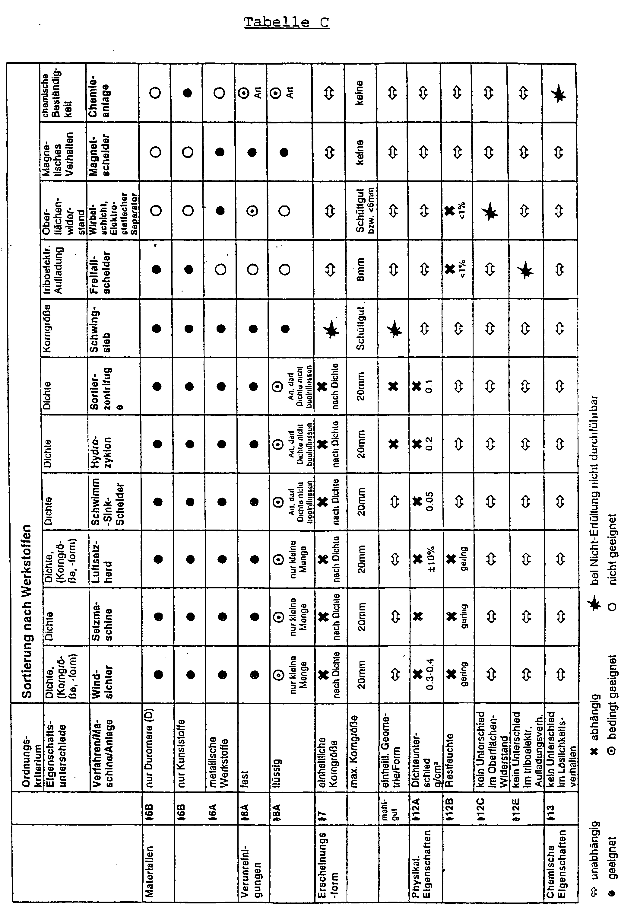
- the key performance indicators relevant to the specified targets can be determined from the following tables A and B and the material can be sorted according to the criteria from the following table C.
- the method according to the invention proves to be particularly advantageous in that that taking into account the specifications a compared to the booth technology, higher benefits can be achieved, with the resulting Material qualities such a starting position create a new processing (possibly with upgrading measures integrated therein) in higher quality Products is possible.
- the composite components may be old parts scrapping vehicles or rejects from the Production or also punching waste during production act as composite components. It is on it to point out that - especially with old products - dependent on the degree of pollution - the described process chains with "wet" process steps are preferable.
- the product structure essentially determines the number and type of the machines and processes for separation in question of the association.
- For use on composite components oriented assessment procedure will be a division of the Recycling routes made in sub-areas. These subareas are group separation, sorting, additional processes (e.g. washing or drying) and processing.
- To determine practice-relevant process steps in accordance with The invention will be used in the comparative evaluation of these sub-areas of effort and benefit assigned exclusion criteria used with which First of all, it is possible to create rough process diagrams. A selection can then be made based on selection criteria Refinement of the flow diagrams take place. Not available
- FIG. 2 shows a partial cross section through the Slide 2 assumes that it is the slide 2 around a three-layer composite component with a top coat layer 5, a layer of e.g. a mixture of Acrylbutadienstyrol (ABS) and polyvinyl chloride (PVC) 6 and one Adhesion layer 7 acts.
- ABS Acrylbutadienstyrol
- PVC polyvinyl chloride
- 3 gives a process chain in the form of a flow diagram again, which is suitable the backing material as the material with the highest percentage by mass to be recovered in the product in single-variety form.
- 2 is punching waste with a carrier made of hard plastic (PP-T 30) too coarse by machine using a cutting mill pre-crushed ground composite particles (unseparated composite), which are then closed using a hammer mill a regrind made of hard plastic (PP-T 30) crumbs and coarser particle remnants are processed (separate Composite), whereupon from the one forming the separate composite Grind the hard plastic (PP-T 30) crumbs using a Zigzag sifter leaving a mixed fraction be recovered according to type.
- So 4a and 4b each go in the form of a flow diagram further process chains emerge, which are suitable for foam and carrier material or To recover film and carrier material according to type.
- So 4a is punching waste with a carrier made of hard plastic (PP-T 30) using a granulator with a sieve insert to coarsely ground composite particles (unseparated Composite), which is then shredded another granulator with sieve insert into one Grist from hard plastic (PP-T 30) crumbs and coarser Particle remnants (separate composite) are processed. From the regrind that forms the separate bond then the hard plastic (PP-T 30) crumbs using of a zigzag sifter, leaving a mixed fraction recovered by type.
- the carrier material is obtained with high yield and high degree of purity.
- the left mixed fraction representing the light goods becomes a sorting centrifuge in a further sorting step supplied, water being used as the separation medium and pure PUR foam recovered becomes.
- 4b is also used Punching waste e.g. from the production of a dashboard body with a carrier made of hard plastic (PP-T 30) using a granulator with a sieve insert Coarse regrind pre-crushed by machine (unseparated composite).
- the strategic goal here is the recovery of Carrier material and film in single-variety form.
- the machine is shredded by means of a modified hammer mill with suction. At this mechanical crushing in the hammer mill is a batch operation, the loading of the Grinding room takes place on such a scale that predominantly the foam is crushed and the film and the carrier material increases the effect of the shuttering of the foam comes into play and the smaller foam particles with the help of a sieve insert a suction can be removed.
- the coarser parts of the Mixed fraction which mainly contains film and carrier material, are opened in batches by opening a discharge flap removed from the hammer mill.
- a zigzag sifter is used for the film and carrier material, where as the property differences in particular Differences in shape can be exploited.
- FIG. 5 schematically shows a general process chain for products of the structure according to FIGS. 1 and 2 using the example of punching waste.
- Mechanical shredding as a measure of compound separation should in the said composite component either be carried out with shredders that according to Impact or impact stress work (preferably Speeds of over 1000 revolutions per minute and Sieve insert with hammer mill with hole width diameter not over 12 mm or with an impact mill with an impact surface grinding track for example with 1/4 division and a gap width over 7.5 mm but under 12 mm or cutting mill (Cutting as a type of stress), with a sieve insert is to be used, the hole width diameter preferably at Should be 5 or 6 mm.
- the choice of the shredder is geared towards the subsequent material sorting steps. When using a free fall separator or Compound separation is preferred in a sorting centrifuge to carry out with the mentioned cutting mill comminution.
- the degree of digestion degree of separation is in the Magnitude of 98% and higher.
- An additional process is necessary if it is for use following sorting procedure necessary prerequisites are not fulfilled, as is the case e.g. Using a free fall separator is the case (prerequisite: Residual moisture well below 1%, i.e. optionally drying process as well as a pretreatment to make up differences in triboelectric Charging behavior of the materials influence or reinforce, as well as grain size ⁇ 8 mm, i.e. possibly additional crushing process).
- the number of material sorting steps required depends on the strategy; for strategy film, foam and carrier material in as pure a sort as possible to recover, a maximum of three sorting steps are required.
- the separation of the carrier material (here PP-T 30) should be preferred when using a "dry process" done with a zigzag sifter, the composite separation with a shredding machine, which according to impact or Impact stress works, or with a cutting mill can be done.
- Example: Sorting with a free fall separator is particularly suitable for sorting one Fraction consisting mainly of PP-T 30 and PVC / ABS film exists because the triboelectric charge is in opposite directions. The above Requirements must be met, as well as the PUR foam must be separated by another process got to.
- FIG. 6a shows a process chain according to the invention for the recovery of Foil, foam and carrier material in sorted form from a stamped scrap with a carrier made of hard plastic (PP-T 30), with which a material recycling with Reuse and reuse can be done.
- a granulator with sieve insert is used for pre-shredding Influencing the maximum grain size used.
- the use of a perforated screen should be the hole width diameter are in the range of 20 to 30 mm.
- the pre-shredding represents an additional process, which has the advantage that at a subsequent crushing step a smaller one Machine type that can only be used on the desired throughput and not due to the otherwise available piece size must be oversized. A compound separation is not connected to it.
- the subsequent mechanical crushing step serves to separate the bond (digestion).
- a comminution machine can be used, which - as is the case with a hammer mill - causes the breakage due to an impact load. Under certain conditions, a good degree of digestion is achieved with 98% and higher.
- a sieve insert should be used. The decisive prerequisites for the high degree of digestion are the use of a sieve insert and the selected speed range. When using a perforated screen, the hole width diameter should not exceed 12 mm. The hammer mill should be operated at relatively high rotor speeds. Successful test results were achieved at revolutions above 1000 min -1 .
- the result of the mechanical crushing mixed material fraction is a first sorting step fed to the PP-T 30 from the carrier in high To obtain yield and with a high degree of purity.
- To the Sorting has a number of methods available based on the exploitation of various property differences with regard to the product structure with the separating materials.
- To sort materials to achieve through wind sifting the ones to be separated Materials in density and / or grain shape and / or grain size differ.
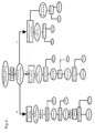
- a suitable method is Wind sifting, with a special zigzag sifter is used as it is shown schematically in FIG. 12 evident. It is a vertical tube with a more or less large number of kinks, with air flowing through it from below.
- the one to be separated It is well fed from above or at one of the kinks.
- its structure is shown schematically in FIG. 12 and is used conventionally for material sorting is a zigzag sifter not a gravity sighting, but a sighting in so-called "vortex rolls".
- Vortex rolls At every bend in the pipe creates a "vortex roller” in which there is a viewing process happening.
- a laminar, low vortex flow like the one in Fig. 12 schematically shown upwind and riser sifter is therefore in accordance with the zigzag sifter Fig. 13 not before.
- the shape influence the sorting process support, but also limit it; the latter then when the particle shape compensates for the density difference.
- the light fraction of polyurethane foam and film sorting is, as explained above, a wind sifter not suitable because the property differences of Compensate geometry and density in such a sorting device and thus a successful separation due to the resulting similar behavior is not possible is.
- a suitable method for sorting the use of an aero stove its sorting principle essentially on the exploitation of density differences based.
- the material mixture to be sorted arrives at the aero hearth via a product inlet to the resonating Feeding device and is there on the machine width distributed and placed on the inclined sieve. On the the product is fluidized and separated according to the specific weight.
- the lighter foam particles migrate to the lower one Screen edge as a stove bottom, while the fraction, the predominantly film particles but also incorrect discharge of PP-T 30 - contains carrier material as a stove overflow the higher sieve edge is discharged.
- the sorting stage is especially the PUR foam high yield and variety purity recovered.
- the third sorting process is said to be optimized for recovery the film can be carried out in single-variety form. It can can be assumed that in particular the in the overflow fraction of PP-T misfeed 30 must be removed. In addition, a zigzag sifter can be used are used, as can be seen from Fig. 6a.
- the process chain shown in FIG. 6b is also based as a strategic goal on the recovery of carrier material, film and foam in sorted form using punching waste from the manufacture of the dashboard base body, which as a composite component according to FIG. 1 with a carrier made of hard plastic (PP-T 30) is constructed.
- the mechanical comminution takes place for compound separation with a cutting mill with a sieve insert. Good results of the degree of digestion are obtained when using a sieve insert with round perforations and a hole width diameter of 6 mm.
- the resulting comminution fraction, in which the various materials are mixed, is subsequently introduced into the sorting centrifuge for sorting.
- the mixed fraction to be separated is fed as a suspension axially into the centrifuge through a standing tube and hits the surface of the water ring rotating at high speed (up to 1500 times acceleration).
- the result is a floating fraction made of PUR foam with a very high degree of purity.
- the sink fraction is returned to the sorting centrifuge for further sorting.
- a salt solution is used as the separation medium, the density of which is set to the order of 1.14 g / cm 3 .
- a saline solution should preferably be used for this.
- the film is obtained as a sink fraction with a high yield and a high degree of purity.
- the floating fraction which in addition to the large proportion of PP-T 30 also has a higher proportion of PUR foam, is dried and fed to a zigzag sifter. The air flow is adjusted so that the PUR foam is discharged as a light fraction at the top.
- the process chain according to FIG. 6c is also strategic Aim to recover carrier material, film and foam in pure form when using Stamping waste from the manufacture of the dashboard base, with the composite component according to FIG. 1 a carrier made of hard plastic (PP-T 30), based.
- a carrier made of hard plastic (PP-T 30), based.
- the coarser parts the mixed fraction, the predominantly film and carrier material is included in batches by opening a discharge flap removed from the hammer mill.
- a zigzag sifter is used for the film and carrier material, where as a property difference in particular Differences in shape can be exploited.
- For the recovery of PUR foam in pure form is the extracted Fraction fed to a sorting step with an aero stove.
- Fig. 7 includes a schematic representation that the Explanation of for the determination of the performance indicators the comparative assessment on which the procedure is based serves, the goal being the determination of practice-relevant Recycling routes for the sort recovery of film, Foam and carrier material when using dashboard punch waste made of PP-T 30, PVC / ABS and PUR. 7, are first of all the possibilities of composite separation such as mechanical Crushing, disassembly, rough disassembly, the Possibilities of material sorting according to density, triboelectric Charging or magnetic behavior and the Processing options such as material recycling or to consider chemical recycling.
- FIG. 8 are the exclusion criteria (ASK) for the applicability of measures for composite separation (VT), material sorting (WS) and processing in the left half and a rough flow chart indicated in the right half, the representation in the left half in FIG. 8 essentially corresponds to FIG. 7.
- ASK exclusion criteria
- VT measure for composite separation
- WS material sorting
- FIG. 7 essentially corresponds to FIG. 7.
- the heavy fraction is sorted in a second stage again about the density of the materials in one Heavy fraction and a light fraction sorted.
- the processing the heavy fraction is then injection molded in injection molded parts, while the light fraction of the first and second sorting stages by pressing into plates or processed into sheets by extrusion.
- ASK The selection criteria for the Implementation of measures for composite separation
- VT Material sorting
- WS Material sorting
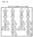
- Fig. 10 shows a section of selected ones Recycling routes (RW) again, which are the basis of the assessment for the strategy of single-grade film recovery, Foam and carrier material e.g. for three-component composite components by means of a point system (performance indicators) serves for defined benefit classes as listed below is. Since the selected recycling routes RW1, RW2, RW3 ... RWn as a result of the intended labeling are understandable, reference is made to the latter.
- Fig. 11 gives a diagram of the cheapest recycling route again.
- the input is a composite component with the composition PP-T 30 59%, ABS / PVC 23% and PUR 18% provided, the mechanical pre-shredding (unseparated compound) and mechanical crushing (separate compound) by means of a cutting mill or a hammer mill followed by three sorting levels.
- To the first sorting stage using an air classifier a heavy fraction to 52%, which is almost pure made of PP-T 30 (99.2%) with 0.5% ABS / PVC and 0.3% PUR component exists.
- a mixed fraction of 29% is in a third Sorting level to approximate using an air classifier pure 24% fraction with 92% ABS / PVC, 6% PP-T 30 and 2% PUR as well as a disposal fraction separated by 5%.
- FIG. 14 illustrates a process chain for redemption of the adhesion promoter of the film with recovery of the Foil without adhesion promoter and foam buildup in single-variety form.
- the Foil as the bottom layer an adhesion promoter and foam buildup on.
- the film is placed in a container Solvent, preferably ethyl methyl ketone for solubility of the adhesion promoter introduced at room temperature, whereupon the solution is filtered such that, on the one hand the dissolved solids such as film without adhesion promoter and essentially foam and on the other hand the solution be preserved.
- Solvent preferably ethyl methyl ketone for solubility of the adhesion promoter introduced at room temperature
- the undissolved solids are used to recover the film either a swim-sink process with water exposed (variant A), where the density differences the unmixed film and a residual fraction with the largest proportion of foam, or after one Variant B becomes the undissolved solids of an evaporation process exposed to evaporation of the solvent, with the single-variety film and a residual fraction with the largest proportion of foam.
Description
Die Erfindung betrifft ein Verfahren zum Zerlegen und sortenreinen Trennen von zu recyclierenden Dreistoff-Verbundteilen mit einem den größten Masseanteil aufweisenden und den Träger bildenden Hartkunststoff (PP-T 30), einer auf dem Träger festhaftend aufgebrachten Zwischenlage aus Schaumstoff und einer auf letzterer außenseitig festhaftend aufgebrachter, flexibler Folie, indem die Verbundteile in mindestens einer Arbeitsstufe zu einem ungetrennten Verbund mittels einer Schneidmühle mit Siebeinlage vorzerkleinert, darauf zu einem getrennten Verbund maschinell zerkleinert und die resultierenden Werkstofffraktionen mindestens einer Werkstoffsortierung unterworfen, getrennt und dann aus dem Verfahrensablauf ausgeschieden und/oder weiterverarbeitet werdenThe invention relates to a process for the disassembly and sorting of materials to be recycled Three-component composite parts with the largest mass fraction and the carrier forming hard plastic (PP-T 30), an intermediate layer adhered to the carrier made of foam and a flexible film adhered to the outside of the latter, by using the composite parts in at least one working step to form an unseparated composite pre-shredded in a cutting mill with a sieve insert, then machine-made into a separate composite crushed and the resulting material fractions of at least one material sorting subjected, separated and then eliminated from the process and / or to be processed further
Bei der Folie der zu reclycierenden Dreistoff-Verbundteile, die konstruktiv kombiniert und insbesondere im Innenraum von Fahrzeugen zu finden sind, handelt es sich in der Regel auch um Verbundsysteme, die drei oder mehr Schichten verschiedener Materialien aufweisen wie z.B. Decklack, Gemisch aus Acrylbutadienstyrol (ABS) und Polyvinylchlorid (PVC) sowie HaftvermittlerWith the film of the three-material composite parts to be recycled, which combines design and can be found especially in the interior of vehicles, they are usually also Composite systems that have three or more layers of different materials, e.g. Top coat, mixture of acrylic butadiene styrene (ABS) and polyvinyl chloride (PVC) as well bonding agent
Ein nach der DE 42 16 638 bekanntes Verfahren der eingangs erwähnten Art soll dafür sorgen, daß sich alle beteiligten Kunststoff-Komponenten in einer für eine Wiederverwendung brauchbaren Sortenreinheit trennen lassen, ohne daß minderwertige oder nichtwiederverwendbare und demgemäß zu entsorgende Mischfraktionen anfallen und ohne, daß Änderungen an den Wertstoffen entstehen, die deren Wiederverwendbarkeit beeinträchtigen oder gar unmöglich machen.A known from DE 42 16 638 method of the type mentioned should ensure that everyone involved Plastic components in one for reuse let usable grade of variety be separated without inferior or non-reusable and therefore to be disposed of Mixed fractions occur and without making changes on the recyclables that are reusable impair or even make impossible.
Zu diesem Zweck wird gemäß der DE 42 16 638 C1 vorgeschlagen, daß zum Zerlegen und sortenreinen Trennen der Dreistoff-Verbundbauteile das selektive Zerkleinern des Schaums durch eine Prallbeanspruchung der Partikel erfolgt, und daß nach dem Entfernen der Schaumstoff-Fraktion das zunächst verbleibende Gemisch aus dickwandigen Hartkunststoffpartikeln und dünnwandigen Folienschnipseln mittels einer vertikalen, wirbelarmen Aufwindsichtung in eine Hartkunststoff-Fraktion und in eine Folienfraktion getrennt wird, wobei die auf einer luftdurchlässigen, etwa horizontalen Unterlage flach und einzeln, d.h. überlappungsfrei aufliegenden Partikel des Gemisches von unten durch einen annähernd vertikal aufsteigenden, wirbelarmen Luftstrom angeströmt werden, wobei nur die leichteren Folienschnipsel angehoben und nach oben fortgetragen und die zurückbleibenden Hartkunststoff-Partikel seitlich auf Siebniveau entfernt werden.For this purpose, according to DE 42 16 638 C1, it is proposed that that for disassembling and separating the three-component composite components the selective crushing of the foam by an impact load of the particles, and that after removing the foam fraction that first remaining mixture of thick-walled hard plastic particles and thin-walled film snippets using a vertical, low-vortex sighting in a hard plastic fraction and separated into a film fraction, whereby on an air-permeable, approximately horizontal surface flat and single, i.e. overlap-free Particles of the mixture from below through an approximately vertical ascending, low-vortex air flow with only the lighter film snippets raised and carried upwards and the remaining hard plastic particles be removed laterally at the sieve level.
Alternativ wird nach der DE 42 16 638 C1 zum Zerlegen und sortenreinen Trennen der Dreistoff-Verbundbauteile angeregt, daß das selektive Zerkleinern des Schaums durch eine Prallbeanspruchung der Partikel erfolgt, und daß nach dem Entfernen der Schaumstoff-Fraktion das zunächst verbleibende Gemisch aus dickwandigen Hartkunststoffpartikeln und dünnwandigen Folienschnipseln mittels einer durch eine aufwärts gerichtete Luftströmung unterstützten Schwingsieb-Trennung in eine Hartkunststoff-Fraktion und in eine Folienfraktion getrennt wird, wobei auf die auf einem zur Horizontalen geneigten Schwingsieb, dessen Maschenweite deutlich kleiner als die Partikel des Gemisches ist, in einer ausgebreiteten Wirrlage aufgeschütteten Partikel ein zum höhergelegenen Rand des Schwingsiebs gerichteter Vibrationsfördereffekt ausgeübt und durch die aufwärts gerichtete Luftströmung die Auflagekraft der Partikel auf dem Schwingsieb und die siebseitig reibungsbedingt auf die Partikel ausübbare schleppkraft reduziert wird, derart, daß der auf die leichteren Folienschnipsel ausgeübte Vibrationsfördereffekt deutlich geringer ist, als der auf die Hartkunststoffpartikel und daß demgemäß zum höhergelegenen Rand des Schwingsiebes lediglich die Hartkunststoffpartikel gefördert werden, wogegen über den tiefer gelegenen Rand des Schwingsiebs die Folienschnipsel ausgetragen werden.Alternatively, according to DE 42 16 638 C1 for disassembling and sorted separation of the three-component composite components, that the selective crushing of the foam by a Impact loading of the particles takes place, and that after Remove the foam fraction the remaining one Mixture of thick-walled hard plastic particles and thin-walled film snippets by means of an upward directional air flow supports vibrating screen separation into a hard plastic fraction and into one Foil fraction is separated, with the on a to Horizontal inclined vibrating screen, the mesh size is significantly smaller than the particles of the mixture, in a scattered confusion of particles Vibration promoting effect directed towards the higher edge of the vibrating screen exercised and by the upward Air flow the bearing force of the particles on the Vibrating screen and the screen side due to friction on the Particulate drag force is reduced such that the vibration-promoting effect exerted on the lighter film snippets is significantly less than that on the Hard plastic particles and that accordingly to the higher one Edge of the vibrating screen only the hard plastic particles are promoted, while over the lower edge of the vibrating screen the foil snippets are discharged.
Verfahren, die sich auf das Zerlegen und Trennen von Zweistoff-Verbundbauteilen beziehen, gehen z.B. aus der JP 32-3909 sowie aus der US 5 042 725 als bekannt hervor, wobei letzteres nur auf Zweistoff-Verbundbauteile mit einer Schaumkomponente beschränkt ist.Procedures that relate to the disassembly and separation of two-component composite components refer, go e.g. from the JP 32-3909 and also known from US Pat. No. 5,042,725, the latter only on two-component composite components with a Foam component is limited.
Die EP 4 22 460 A beschreibt weiterhin Verfahren zum Zerteilen
und Sortieren der unterschiedlichen Kunststoffe von
Stanzabfällen aus Fahrzeug-Armaturentafeln, die aus einer
Basislage aus hydrophilem Polyurethanschaum und aus einer
damit verbundenen Außenhaut aus hydrophober PVC-Folie
bestehen. Danach soll im Anschluß an eine maschinelle Zerkleinerung
unter dem Einfluß von Wasser der PUR-Schaumstoff
aufquellen und sich von der Folie ablösen. Als problematisch
kann sich bei diesem bekannten Verfahren herausstellen,
ob die Kräfte, die durch die mit Wasser verursachte
Aufquellung der Schaumreste auf die Klebeverbindung
zwischen Schaumstoff und Folie ausgeübt werden können, in
Anbetracht der Elastizität und Komprimierbarkeit des
Schaumstoffs ausreichen werden, um die wesentlich höheren
Klebekräfte überwinden zu können.
Die vorliegende Erfindung geht aus von der Zielstellung,
ein Verfahren zum Zerlegen und sortenreinen Trennen von zu
recyclierenden Verbundbauteilen gemäß der eingangs erwähnten
Art auf der Basis einer vergleichenden Bewertung von Leistungskennziffern, die anhand
praktischer Untersuchungen von Aufwand und Nutzen verschiedener Verwertungsweg z.B. für
Stanzabfälle ermittelbar sind, für unterschiedliche strategische Zielvorgaben optimal zu gestalten.
Solche Zielvorgaben sind :
Der Erfindung liegt somit die Aufgabe zu Grunde, ein Verfahren der eingangs erwähnten Art so zu gestalten, daß im Vergleich zum Stand der Technik eine effektivere Zerlegung und sortenreine Trennung von zu recyclierenden Dreistoff-Verbundbauteilen unter Berücksichtigung der zuvor genannten Vorgaben erzielbar ist.The invention is therefore based on the object of a method of the type mentioned at the beginning shape that compared to the prior art, a more effective decomposition and pure Separation of three-component composite components to be recycled, taking into account the previously mentioned specifications can be achieved.
Diese Aufgabe wird erfindungsgemäß durch die aus dem Kennzeichen des Patentanspruchs 1
hervorgehenden Verfahrensschritte gelöst.This object is achieved by the characterizing part of
Vorteilhafte Weiterbildungen des Verfahrens ergeben sich aus den Patentansprüchen 2 und 3.Advantageous further developments of the method result from
Die für die genannten Zielvorgaben relevanten Leistungskennziffern können aus den nachfolgenden
Tabelle A bzw. B ermittelt werden und die Werkstoffsortierung kann nach den aus der
nachfolgenden Tabelle C hervorgehenden Kriterien erfolgen.


Die Ausscheidung und/oder Weiterverarbeitung der
resultierenden Werkstofffraktionen kann unter Berücksichtigung
der Ausschlußkriterien gemäß Tabelle D vollzogen werden.

Das erfindungsgemäße Verfahren erweist sich insbesondere dadurch als vorteilhaft, daß unter Berücksichtigung der Vorgaben ein im Vergleich zum Stand der Technik höherer Nutzen erzielbar ist, wobei die resultierenden Materialqualitäten auch eine solche Ausgangsposition schaffen, daß eine erneute Verarbeitung (evtl. mit darin integrierten Aufwertungsmaßnahmen) in höherwertigen Produkten möglich ist.The method according to the invention proves to be particularly advantageous in that that taking into account the specifications a compared to the booth technology, higher benefits can be achieved, with the resulting Material qualities such a starting position create a new processing (possibly with upgrading measures integrated therein) in higher quality Products is possible.
Insbesondere bringt das erfindungsgemäße Verfahren zur Verbund- und Werkstofftrennung folgende Vorteile mit sich:
- Es wird ein guter Aufschluß- bzw. Verbundtrennungsgrad bezüglich der verschiedenen Kunststoffe/Werkstoffe aus dem Verbundbauteil erzielt (Größenordnung: mindestens 98 %), so daß Folien- und Hartkunststoffteile gar nicht oder nur noch geringfügig mit Schaumstoff behaftet sind.
- Entsprechend der gewünschten, strategischen Zielvorgaben führt das erfindungsgemäße Verfahren zu der jeweils gewünschten Anzahl und Art von Kunststoff/Werkstofffraktionen mit hoher Sortenreinheit und hoher Ausbeute.
- Es handelt sich größtenteils µm großtechnisch problemlos umsetzbare Verfahrensmaßmahmen, da bereits anderweitig bewährte Komponenten eingesetzt werden.
- Deponieraum und Entsorgungskosten werden eingespart sowie Ressourcen geschont.
- A good degree of digestion or composite separation is achieved with regard to the various plastics / materials from the composite component (order of magnitude: at least 98%), so that foil and hard plastic parts are not or only slightly contaminated with foam.
- In accordance with the desired strategic objectives, the method according to the invention leads to the desired number and type of plastic / material fractions with high grade purity and high yield.
- For the most part, it involves process measures that can be easily implemented on an industrial scale, since components that have already been proven in other ways are already being used.
- Landfill space and disposal costs are saved and resources conserved.
Auch ist es mit der Erfindung möglich, bei Verbundbauteilen des o.g. Aufbaus den Haftvermittler der Folie zu lösen und damit eine vollständige Abtrennung des Schaumstoffs von der Folie zu erreichen.It is also possible with the invention in the case of composite components of the above Construction to loosen the adhesion promoter of the film and thus a complete separation of the foam from the Reach slide.
Bei den Verbundbauteilen kann es sich um Alt-Teile aus zu verschrottenden Fahrzeugen oder um Ausschußteile aus der Produktion oder auch um Stanzabfälle bei der Produktion derart aufgebauter Verbundbauteile handeln. Es ist darauf hinzuweisen, daß insbesondere bei Altprodukten - abhängig vom Verschmutzungsgrad - die beschriebenen Verfahrensketten mit "nassen" Prozeßschritten zu bevorzugen sind.The composite components may be old parts scrapping vehicles or rejects from the Production or also punching waste during production act as composite components. It is on it to point out that - especially with old products - dependent on the degree of pollution - the described process chains with "wet" process steps are preferable.
Der Produktaufbau bestimmt im wesentlichen Anzahl und Art der in Frage kommenden Maschinen und Verfahren zur Trennung des Verbundes. Bei dem zur Anwendung auf Verbundbauteile ausgerichteten Bewertungsverfahren wird eine Aufteilung der Verwertungswege in Teilbereiche vorgenommen. Diese Teilbereiche sind Verbundtrennung, Sortierung, Zusatzprozesse (beispielsweise Waschen oder Trocknen) und Verarbeitung. Zur Ermittlung von praxisrelevanten Verfahrensschritten gemäß der Erfindung werden im Rahmen der vergleichenden Bewertung von Aufwand und Nutzen aufgestellte diesen Teilbereichen zugeordnete Ausschlußkriterien herangezogen, mit denen zunächst die Erstellung grober Ablaufschemata möglich ist. Aufgrund von Auswahlkriterien kann daran anschließend eine Verfeinerung der Ablaufschemata erfolgen. Nicht vorhandene The product structure essentially determines the number and type of the machines and processes for separation in question of the association. For use on composite components oriented assessment procedure will be a division of the Recycling routes made in sub-areas. These subareas are group separation, sorting, additional processes (e.g. washing or drying) and processing. To determine practice-relevant process steps in accordance with The invention will be used in the comparative evaluation of these sub-areas of effort and benefit assigned exclusion criteria used with which First of all, it is possible to create rough process diagrams. A selection can then be made based on selection criteria Refinement of the flow diagrams take place. Not available
Daten zur Durchführung und Bewertung werden an Beispielen aus der Produktions mit praktischen Untersuchungen ermittelt. Die Bewertung des Aufwands wird mit Hilfe eines Punktsystems vorgenommen, wobei die Differenz von einem Punkt einer bestimmten Kostenspanne zugeordnet ist. Auf diese Weise ergeben sich die Leistungskennziffern.Data for implementation and evaluation are based on examples from production with practical Investigations determined. The effort is assessed using a point system made, the difference from a point assigned to a certain cost range is. In this way, the performance indicators result.
Die Erfindung wird nun anhand der Zeichnungen erläutert, in denen lediglich Fig. 6a ein
Ausführungsbeispiel der Erfindung zeigt. In den Zeichnungen sind:
Das in Fig. 1 ausschnittweise im Querschnitt dargestellte Verbundbauteil 1 ist wie folgt aufgebaut:
- tragender, in der Regel dickwandiger als die äußere
Folie ausgebildeten Träger 4 aus einem verstärkten Hartkunststoff,
beispielsweise talkumverstärktes Polypropylen
wie PP-
T 30 - diesen Träger festhaftend umgebende Zwischenlage 3 aus Schaumstoff, z.B. Polyurethan und
- außenseitig darauf festhaftend angebrachte,
flexible Folie 2, bei der es sich in der Regel auch um ein Verbundsystem handelt und deren wesentlicher Bestandteil beispielsweise ein Gemisch aus Acrylbutadienstyrol (ABS) und Polyvinylchlorid (PVC) darstellt.
- load-bearing, generally thick-
walled carrier 4 made of a reinforced hard plastic, for example talcum-reinforced polypropylene such as PP-T 30 - this carrier adherent intermediate layer 3 made of foam, such as polyurethane and
-
Flexible film 2 adhered to the outside of the film, which is generally also a composite system and whose essential component is, for example, a mixture of acrylic butadiene styrene (ABS) and polyvinyl chloride (PVC).
Aus Fig. 2 geht ein ausschnittweiser Querschnitt durch die
Folie 2 unter der Annahme hervor, daß es sich bei der Folie
2 um ein dreischichtiges Verbundbauteil mit einer Decklackschicht
5, einer Schicht aus z.B. einem Gemisch aus Acrylbutadienstyrol
(ABS) und Polyvinylchlorid (PVC) 6 und einer
Haftvermittlerschicht 7 handelt.2 shows a partial cross section through the
Fig. 3 gibt in Form eines Fließschemas eine Verfahrenskette wieder, die geeignet ist, das Trägermaterial als den Werkstoff mit dem höchsten Massenprozentanteil im Produkt in sortenreiner Form wiederzugewinnen. Gemäß Fig. 2 wird Stanzabfall mit Träger aus Hartkunststoff (PP-T 30) maschinell mittels einer Schneidmühle zu grob gemahlenen Verbundpartikeln (ungetrennter Verbund) vorzerkleinert, die anschließend mittels einer Hammermühle zu einem Mahlgut aus Hartkunststoff-(PP-T 30)-Krümeln und gröberen Partikelreststücken verarbeitet werden (getrennter Verbund), worauf aus dem den getrennten Verbund bildenden Mahlgut die Hartkunststoff-(PP-T 30)-Krümel mittels eines Zick-Zack-Sichters unter Zurücklassung einer Mischfraktion sortenrein zurückgewonnen werden.3 gives a process chain in the form of a flow diagram again, which is suitable the backing material as the material with the highest percentage by mass to be recovered in the product in single-variety form. 2 is punching waste with a carrier made of hard plastic (PP-T 30) too coarse by machine using a cutting mill pre-crushed ground composite particles (unseparated composite), which are then closed using a hammer mill a regrind made of hard plastic (PP-T 30) crumbs and coarser particle remnants are processed (separate Composite), whereupon from the one forming the separate composite Grind the hard plastic (PP-T 30) crumbs using a Zigzag sifter leaving a mixed fraction be recovered according to type.
Aus den Fig. 4a und 4b gehen jeweils in Form eines Fließschemas weitere Verfahrensketten hervor, die geeignet sind, Schaumstoff und Trägermaterial bzw. Folien- und Trägermaterial sortenrein zurückzugewinnen. So wird gemäß Fig. 4a Stanzabfall mit einem Träger aus Hartkunststoff (PP-T 30) mittels einer Schneidmühle mit Siebeinlage zu grob gemahlenen Verbundpartikeln (ungetrennter Verbund) maschinell vorzerkleinert, die anschließend mittels einer weiteren Schneidmühle mit Siebeinlage zu einem Mahlgut aus Hartkunststoff-(PP-T 30)-Krümeln und gröberen Partikelreststücken (getrennter Verbund) verarbeitet werden. Aus dem den getrennten Verbund bildenden Mahlgut werden die Hartkunststoff-(PP-T 30)-Krümel dann mittels eines Zick-Zack-Sichters unter Zurücklassung einer Mischfraktion sortenrein zurückgewonnen. Das Trägermaterial wird mit hoher Ausbeute und hohem Reinheitsgrad erhalten. Die zurückgelassene, das Leichtgut darstellende Mischfraktion wird in einem weiteren Sortierschritt einer Sortierzentrifuge zugeführt, wobei als Trennmedium Wasser verwendet und sortenreiner PUR-Schaumstoff zurückgewonnen wird.4a and 4b each go in the form of a flow diagram further process chains emerge, which are suitable for foam and carrier material or To recover film and carrier material according to type. So 4a is punching waste with a carrier made of hard plastic (PP-T 30) using a granulator with a sieve insert to coarsely ground composite particles (unseparated Composite), which is then shredded another granulator with sieve insert into one Grist from hard plastic (PP-T 30) crumbs and coarser Particle remnants (separate composite) are processed. From the regrind that forms the separate bond then the hard plastic (PP-T 30) crumbs using of a zigzag sifter, leaving a mixed fraction recovered by type. The carrier material is obtained with high yield and high degree of purity. The left mixed fraction representing the light goods becomes a sorting centrifuge in a further sorting step supplied, water being used as the separation medium and pure PUR foam recovered becomes.
Bei der Verfahrenskette gemäß Fig. 4b wird ebenfalls Stanzabfall z.B. aus der Fertigung eines Armaturentafelgrundkörpers mit einem Träger aus Hartkunststoff (PP-T 30) mittels einer Schneidmühle mit Siebeinlage zu grobem Mahlgut maschinell vorzerkleinert (ungetrennter Verbund). Strategisches Ziel ist hier die Rückgewinnung von Trägermaterial und Folie in sortenreiner Form. Zur Trennung des Verbundes erfolgt die maschinelle Zerkleinerung mittels einer modifizierten Hammermühle mit Absaugung. Bei dieser maschinellen Zerkleinerung in der Hammermühle handelt es sich um einen chargenweisen Betrieb, wobei die Beladung des Mahlraums in einer solchen Größenordnung erfolgt, daß vorwiegend der Schaumstoff zerkleinert wird und bei der Folie und dem Trägermaterial verstärkt der Effekt des Abschalens des Schaumstoffs zum Tragen kommt und die kleineren Schaumstoffpartikel durch eine Siebeinlage ständig mit Hilfe einer Absaugung entfernt werden. Die gröberen Teile der Mischfraktion, die überwiegend Folie und Trägermaterial beinhaltet, werden chargenweise durch Öffnen einer Austragsklappe aus der Hammermühle entfernt. Zur Sortierung von Folie und Trägermaterial wird ein Zick-Zack-Sichter eingesetzt, wobei als Eigenschaftsunterschiede insbesondere die Formunterschiede ausgenutzt werden. 4b is also used Punching waste e.g. from the production of a dashboard body with a carrier made of hard plastic (PP-T 30) using a granulator with a sieve insert Coarse regrind pre-crushed by machine (unseparated composite). The strategic goal here is the recovery of Carrier material and film in single-variety form. For separation The machine is shredded by means of a modified hammer mill with suction. At this mechanical crushing in the hammer mill is a batch operation, the loading of the Grinding room takes place on such a scale that predominantly the foam is crushed and the film and the carrier material increases the effect of the shuttering of the foam comes into play and the smaller foam particles with the help of a sieve insert a suction can be removed. The coarser parts of the Mixed fraction, which mainly contains film and carrier material, are opened in batches by opening a discharge flap removed from the hammer mill. For sorting A zigzag sifter is used for the film and carrier material, where as the property differences in particular Differences in shape can be exploited.
Fig. 5 zeigt schematisch eine allgemeine Verfahrenskette für Produkte des Aufbaus nach den Fig. 1 und 2 am Beispiel von Stanzabfällen.5 schematically shows a general process chain for products of the structure according to FIGS. 1 and 2 using the example of punching waste.
Bei Produkten wie den Stanzabfällen, deren maximale Abmessungen wie bei den Stanzabfällen in der Größenordnung von 200 x 350 mm (Wanddicke: 3 ... 10 mm) liegen, ist eine einstufige Vorzerkleinerung ausreichend, die bei dem beschriebenen Aufbau mit Folie, Schaumstoff und Kunststoffträgerteil (Stanzabfall) bevorzugt in einer Schneidmühle durchgeführt werden sollte. Im Falle von größeren Abmessungen ist mindestens eine weitere Vorzerkleinerungsstufe hinzuzufügen, wobei eine langsamer als die Schneidmühle laufende Zerkleinerungsmaschine z.B. ein Mehrwellenzerkleinerer oder ein Schneidgranulator eingesetzt werden sollte.For products such as punching waste, their maximum dimensions as with punching waste on the order of 200 x 350 mm (wall thickness: 3 ... 10 mm) is a one-stage Pre-shredding sufficient for the described Structure with foil, foam and plastic carrier part (Punching waste) preferably in a cutting mill should be done. In the case of larger ones Dimensions is at least one further pre-shredding stage add one slower than that Cutting mill running shredding machine e.g. a multi-shaft shredder or a cutting granulator is used should be.
Eine maschinelle Zerkleinerung als Maßnahme der Verbundtrennung sollte bei dem besagten Verbundbauteil entweder mit Zerkleinerungsgeräten durchgeführt werden, die nach Prall- bzw. Schlagbeanspruchung arbeiten (vorzugsweise Umdrehungszahlen von über 1000 Umdrehungen pro Minute und Siebeinlage bei Hammermühle mit Lochweitendurchmesser nicht über 12 mm oder mit Prallmühle mit einer Prallflächenmahlbahn beispielsweise mit 1/4 Teilung und einer Spaltweite über 7,5 mm aber unter 12 mm oder aber Schneidmühle (Schneiden als Beanspruchungsart), wobei eine Siebeinlage einzusetzen ist, deren Lochweitendurchmesser bevorzugt bei 5 oder 6 mm liegen sollte. Die Wahl der Zerkleinerungsmaschine ist ausgerichtet auf die nachfolgenden Werkstoffsortierschritte. Bei Einsatz eines Freifallscheiders oder einer Sortierzentrifuge ist die Verbundtrennung bevorzugt mit der genannten Schneidmühlenzerkleinerung durchzuführen. Der Aufschlußgrad (Grad der Verbundtrennung) liegt in der Größenordnung von 98 % und höher. Mechanical shredding as a measure of compound separation should in the said composite component either be carried out with shredders that according to Impact or impact stress work (preferably Speeds of over 1000 revolutions per minute and Sieve insert with hammer mill with hole width diameter not over 12 mm or with an impact mill with an impact surface grinding track for example with 1/4 division and a gap width over 7.5 mm but under 12 mm or cutting mill (Cutting as a type of stress), with a sieve insert is to be used, the hole width diameter preferably at Should be 5 or 6 mm. The choice of the shredder is geared towards the subsequent material sorting steps. When using a free fall separator or Compound separation is preferred in a sorting centrifuge to carry out with the mentioned cutting mill comminution. The degree of digestion (degree of separation) is in the Magnitude of 98% and higher.
Ein Zusatzprozeß ist dann notwendig, wenn die für den Einsatz nachfolgender Sortierverfahren notwendigen Voraussetzungen nicht erfüllt sind, wie dies z.B. bei Verwendung eines Freifallscheiders der Fall ist (Voraussetzung: Restfeuchte weit unter 1 %, d.h. gegebenenfalls Trocknungsprozeß sowie eine Vorbehandlung, um Unterschiede im triboelektrischen Aufladungsverhalten der Werkstoffe gezielt zu beeinflussen bzw. zu verstärken, sowie Korngröße < 8 mm, d.h. eventuell zusätzlicher Zerkleinerungsprozeß).An additional process is necessary if it is for use following sorting procedure necessary prerequisites are not fulfilled, as is the case e.g. Using a free fall separator is the case (prerequisite: Residual moisture well below 1%, i.e. optionally drying process as well as a pretreatment to make up differences in triboelectric Charging behavior of the materials influence or reinforce, as well as grain size <8 mm, i.e. possibly additional crushing process).
Die Anzahl der erforderlichen Werkstoffsortierschritte
hängt von der Strategie ab; bei Strategie Folie, Schaumstoff
und Trägermaterial in möglichst sortenreiner Form
zurückzugewinnen, sind maximal drei Sortierschritte erforderlich.
Die Abtrennung des Trägermaterials (hier PP-T 30)
sollte bei Einsatz eines "trockenen Verfahrens" bevorzugt
mit einem Zick-Zack-Sichter erfolgen, wobei die Verbundtrennung
mit einer Zerkleinerungsmaschine, die nach Prallbzw.
Schlagbeanspruchung arbeitet, oder mit einer Schneidmühle
erfolgen kann. Beispiel: Eine Sortierung mit Freifallscheider
eignet sich insbesondere zur Sortierung einer
Fraktion, die überwiegend aus PP-T 30 und PVC/ABS-Folie
besteht, da die triboelektrische Aufladung gegensinnig ist.
Die o.g. Voraussetzungen müssen erfüllt sein, sowie der
PUR-Schaumstoff durch ein anderes Verfahren abgetrennt sein
muß.The number of material sorting steps required
depends on the strategy; for strategy film, foam
and carrier material in as pure a sort as possible
to recover, a maximum of three sorting steps are required.
The separation of the carrier material (here PP-T 30)
should be preferred when using a "dry process"
done with a zigzag sifter, the composite separation
with a shredding machine, which according to impact or
Impact stress works, or with a cutting mill
can be done. Example: Sorting with a free fall separator
is particularly suitable for sorting one
Fraction consisting mainly of PP-
Ist ein "nasses" Sortierverfahren wie bei der Sortierzentrifuge angewendet worden, so ist als Zusatzprozeß vor der Verarbeitung ein Trocknungsschritt voranzustellen oder bei Einsatz eines anderen flüssigen Sortiermediums als Wasser (z.B. Salzlösung) ein Wasch- und Trocknungsschritt. Anschließend ist eine Verarbeitung möglich.Is a "wet" sorting process like the sorting centrifuge has been applied as an additional process to precede the processing with a drying step or when using a liquid sorting medium other than Water (e.g. saline solution) a washing and drying step. Processing is then possible.
In Fig. 6a ist eine erfindungsgemäße Verfahrenskette zur Rückgewinnung von Folie, Schaumstoff und Trägermaterial in sortenreiner Form aus einem Stanzabfall mit Träger aus Hartkunststoff (PP-T 30) dargestellt, mit der ein Materialrecycling mit Wieder- und Weiterverwendung durchgeführt werden kann. Zur Vorzerkleinerung wird eine Schneidmühle mit Siebeinlage zur Beeinflussung der maximalen Korngröße eingesetzt. Bei Einsatz eines Lochsiebes sollte der Lochweitendurchmesser im Bereich von 20 bis 30 mm liegen. Die Vorzerkleinerung stellt einen Zusatzprozeß dar, der den Vorteil hat, daß bei einem nachfolgenden Zerkleinerungsschritt ein kleinerer Maschinentyp verwendet werden kann, der nur auf die gewünschte Durchsatzleistung ausgerichtet sein und nicht aufgrund der andernfalls vorliegenden Aufgabestückgröße überdimensioniert werden muß. Eine Verbundtrennung ist damit nicht verbunden.6a shows a process chain according to the invention for the recovery of Foil, foam and carrier material in sorted form from a stamped scrap with a carrier made of hard plastic (PP-T 30), with which a material recycling with Reuse and reuse can be done. to A granulator with sieve insert is used for pre-shredding Influencing the maximum grain size used. at The use of a perforated screen should be the hole width diameter are in the range of 20 to 30 mm. The pre-shredding represents an additional process, which has the advantage that at a subsequent crushing step a smaller one Machine type that can only be used on the desired throughput and not due to the otherwise available piece size must be oversized. A compound separation is not connected to it.
Der nachfolgende maschinelle Zerkleinerungsschritt dient der Trennung des Verbundes (Aufschluß). Dazu kann eine Zerkleinerungsmaschine eingesetzt werden, die - wie das bei einer Hammermühle der Fall ist - den Bruch aufgrund einer Prallbeanspruchung herbeiführt. Damit wird unter bestimmten Voraussetzungen ein mit 98 % und höher ausreichend guter Aufschlußgrad erzielt. Ebenso wie bei der Vorzerkleinerung ist eine Siebeinlage zu verwenden. Maßgebliche Voraussetzungen für den hohen Aufschlußgrad sind die Anwendung einer Siebeinlage sowie der ausgewählte Drehzahlbereich. Bei Verwendung eines Lochsiebes sollte der Lochweitendurchmesser nicht über 12 mm liegen. Die Hammermühle sollte mit relativ hohen Rotordrehzahlen betrieben werden. Erfolgreiche Untersuchungsergebnisse wurden bei Umdrehungszahlen über 1000 min-1 erreicht.The subsequent mechanical crushing step serves to separate the bond (digestion). For this purpose, a comminution machine can be used, which - as is the case with a hammer mill - causes the breakage due to an impact load. Under certain conditions, a good degree of digestion is achieved with 98% and higher. As with pre-shredding, a sieve insert should be used. The decisive prerequisites for the high degree of digestion are the use of a sieve insert and the selected speed range. When using a perforated screen, the hole width diameter should not exceed 12 mm. The hammer mill should be operated at relatively high rotor speeds. Successful test results were achieved at revolutions above 1000 min -1 .
Die aus der maschinellen Zerkleinerung resultierende
gemischte Werkstofffraktion wird einem ersten Sortierschritt
zugeführt, um das PP-T 30 aus dem Träger in hoher
Ausbeute und mit hohem Reinheitsgrad zu erhalten. Zum
Sortieren stehen eine Reihe von Verfahren zur Verfügung,
die auf der Ausnutzung von verschiedenen Eigenschaftsunterschieden
hinsichtlich des Produktaufbaus mit den zu
trennenden Werkstoffen beruhen. Um eine Werkstoffsortierung
über Windsichtung zu erzielen, sollten sich die zu trennenden
Materialien in Dichte und/oder Kornform und/oder Korngröße
unterscheiden. Ein dazu geeignetes Verfahren ist die
Windsichtung, wobei als spezieller Gerätetyp ein Zick-Zack-Sichter
eingesetzt wird, wie er schematisch aus Fig. 12
hervorgeht. Dabei handelt es sich um ein senkrechtes Rohr
mit einer mehr oder weniger großen Anzahl von Knickstellen,
das von unten her mit Luft durchströmt wird. Das zu trennende
Gut wird von oben bzw. an einer der Knickstellen aufgegeben.
Im Unterschied zu einem Aufwind- bzw. Steigrohrsichter,
dessen Aufbau schematisch in Fig. 12 dargestellt
ist und der herkömmlich zur Werkstoffsortierung eingesetzt
wird, handelt es sich bei einem Zick-Zack-Sichter
nicht um eine Schwerkraftsichtung, sondern um eine Sichtung
in sogenannten "Wirbelwalzen". An jeder Knickung des Rohres
entsteht eine "Wirbelwalze", in der sich ein Sichtvorgang
abspielt. Eine laminare, wirbelarme Strömung wie bei dem in
Fig. 12 schematisch dargestellten Aufwind- bzw. Steigrohrsichter
liegt daher bei dem Zick-Zack-Sichter gemäß
Fig. 13 nicht vor. Der Formeinfluß kann den Sortierprozeß
unterstützen, ihn aber auch einschränken; letzteres dann,
wenn die Partikelform die Dichtedifferenz kompensiert. Dies
ist in diesem Fall beim Schaumstoff und dem Folienmaterial
der Fall. So werden das flächige Folienmaterial und bezüglich
der Dichte weit unter den Werten von Folie und PP-T 30
liegende Schaumstoff gemeinsam als Leichtfraktion mit dem
Luftstrom nach oben ausgetragen, während das talkumverstärkte
Polypropylen aus dem Träger als Schwergut ausgetragen
wird.The result of the mechanical crushing
mixed material fraction is a first sorting step
fed to the PP-
Um die Leichtfraktion nach Polyurethanschaumstoff und Folie
zu sortieren, ist, wie oben erläutert, ein Windsichter
nicht geeignet, da sich die Eigenschaftsunterschiede von
Geometrie und Dichte in einem solchen Sortiergerät kompensieren
und somit eine erfolgreiche Trennung aufgrund des
daraus resultierenden ähnlichen Verhaltens nicht möglich
ist. Hier bietet sich als geeignetes Verfahren zur Sortierung
der Einsatz eines Aeroherdes an, dessen Sortierprinzip
im wesentlichen auf der Ausnutzung von Dichteunterschieden
beruht. Bei dem Aeroherd gelangt das zu sortierende Werkstoffgemisch
über einen Produkteinlauf zur mitschwingenden
Speisevorrichtung und wird dort auf die Maschinenbreite
verteilt und auf das längsgeneigte Sieb aufgegeben. Auf der
luftdurchströmten Siebfläche wird das Produkt fluidisiert
und entsprechend dem spezifischen Gewicht getrennt. Die
leichteren Schaumstoffpartikel wandern dabei zur tieferliegenden
Siebkante als Herdunterlauf, während die Fraktion,
die überwiegend Folienpartikel aber auch noch Fehlaustrag
von PP-T 30 - Trägermaterial enthält, als Herdüberlauf an
der höherliegenden Siebkante ausgetragen wird. Bei dieser
Sortierstufe wird insbesondere der PUR-Schaumstoff mit
hoher Ausbeute und Sortenreinheit zurückgewonnen. Der
dritte Sortierprozeß soll optimiert auf die Rückgewinnung
der Folie in sortenreiner Form durchgeführt werden. Es kann
davon ausgegangen werden, daß hierzu insbesondere der in
der Herdüberlauffraktion vorliegende Fehlaustrag von PP-T
30 entfernt werden muß. Dazu kann wiederum ein Zick-Zack-Sichter
eingesetzt werden, wie aus Fig. 6a ersichtlich ist.The light fraction of polyurethane foam and film
sorting is, as explained above, a wind sifter
not suitable because the property differences of
Compensate geometry and density in such a sorting device
and thus a successful separation due to the
resulting similar behavior is not possible
is. Here is a suitable method for sorting
the use of an aero stove, its sorting principle
essentially on the exploitation of density differences
based. The material mixture to be sorted arrives at the aero hearth
via a product inlet to the resonating
Feeding device and is there on the machine width
distributed and placed on the inclined sieve. On the
the product is fluidized
and separated according to the specific weight. The
lighter foam particles migrate to the lower one
Screen edge as a stove bottom, while the fraction,
the predominantly film particles but also incorrect discharge
of PP-T 30 - contains carrier material as a stove overflow
the higher sieve edge is discharged. At this
The sorting stage is especially the PUR foam
high yield and variety purity recovered. The
third sorting process is said to be optimized for recovery
the film can be carried out in single-variety form. It can
can be assumed that in particular the in
the overflow fraction of PP-
Der aus Fig. 6b hervorgehenden Verfahrenskette liegt ebenfalls
als strategisches Ziel die Rückgewinnung von Trägermaterial,
Folie und Schaumstoff in sortenreiner Form bei
Verwendung von Stanzabfall aus der Fertigung des Armaturentafelgrundkörpers
zugrunde, der als Verbundbauteil gemäß
Fig. 1 mit einem Träger aus Hartkunststoff (PP-T 30) aufgebaut
ist. Im Anschluß an die maschinelle Vorzerkleinerung,
die hier wie bei der Verfahrenskette gemäß Fig. 6a vor sich
geht, erfolgt die maschinelle Zerkleinerung zur Verbundtrennung
mit einer Schneidmühle mit Siebeinlage. Gute
Ergebnisse des Aufschlußgrades ergeben sich bei Verwendung
einer Siebeinlage mit Rundlochung und einem Lochweitendurchmesser
von 6 mm. Die daraus resultierende Zerkleinerungsfraktion,
in der die verschiedenen Werkstoffe gemischt
vorliegen, wird nachfolgend zur Sortierung in die Sortierzentrifuge
eingebracht. Die zu trennende Mischfraktion wird
als Suspension axial in die Zentrifuge durch ein stehendes
Rohr aufgegeben und trifft auf die Oberfläche des mit hoher
Drehzahl (bis 1500-fache Beschleunigung) umlaufenden
Wasserrings. Die Teilchen mit höherer Dichte als die des
Wassers sinken zum Zentrifugenmantel hin ab, während die
mit geringerer Dichte als Wasser aufschwimmen. Im konischen
Teil findet eine Entwässerung statt. Bei der Durchführung
mit Wasser als Trennmedium resultiert als Ergebnis eine
Schwimmfraktion aus PUR-Schaumstoff mit sehr hohem Reinheitsgrad.
Die Sinkfraktion wird zur weiteren Sortierung
erneut der Sortierzentrifuge zugeführt. Als Trennmedium
kommt eine Salzlösung zum Einsatz, deren Dichte in der
Größenordnung von 1,14 g/cm3 eingestellt ist. Bevorzugt
sollte dafür eine Kochsalzlösung eingesetzt werden. Aus
diesem Sortierschritt erhält man als Sinkfraktion die Folie
mit hoher Ausbeute und hohem Reinheitsgrad. Die Schwimmfraktion,
die außer dem großen Anteil PP-T 30 auch noch
einen höheren Anteil PUR-Schaumstoff aufweist, wird
getrocknet und einem Zick-Zack-Sichter zugeführt. Der Luftstrom
wird so eingestellt, daß der PUR-Schaumstoff als
Leichtfraktion oben ausgetragen wird.The process chain shown in FIG. 6b is also based as a strategic goal on the recovery of carrier material, film and foam in sorted form using punching waste from the manufacture of the dashboard base body, which as a composite component according to FIG. 1 with a carrier made of hard plastic (PP-T 30) is constructed. Following the mechanical pre-comminution, which is carried out here as in the process chain according to FIG. 6a, the mechanical comminution takes place for compound separation with a cutting mill with a sieve insert. Good results of the degree of digestion are obtained when using a sieve insert with round perforations and a hole width diameter of 6 mm. The resulting comminution fraction, in which the various materials are mixed, is subsequently introduced into the sorting centrifuge for sorting. The mixed fraction to be separated is fed as a suspension axially into the centrifuge through a standing tube and hits the surface of the water ring rotating at high speed (up to 1500 times acceleration). The particles with a higher density than those of the water sink towards the centrifuge jacket, while those with a lower density than water float. Drainage takes place in the conical part. When carried out with water as the separating medium, the result is a floating fraction made of PUR foam with a very high degree of purity. The sink fraction is returned to the sorting centrifuge for further sorting. A salt solution is used as the separation medium, the density of which is set to the order of 1.14 g / cm 3 . A saline solution should preferably be used for this. From this sorting step, the film is obtained as a sink fraction with a high yield and a high degree of purity. The floating fraction, which in addition to the large proportion of PP-
Auch der Verfahrenskette nach Fig. 6c liegt als strategisches Ziel die Rückgewinnung von Trägermaterial, Folie und Schaumstoff in sortenreiner Form bei Verwendung von Stanzabfall aus der Fertigung des Armaturentafelgrundkörpers, der als Verbundbauteil gemäß Fig. 1 mit einem Träger aus Hartkunststoff (PP-T 30) aufgebaut ist, zugrunde. Nach erfolgter maschineller Vorzerkleinerung wie bei der Verfahrenskette gemäß Fig. 6a wird die maschinelle Zerkleinerung zur Trennung des Verbundes wie bei der Verfahrenskette nach Fig. 4b in einer Hammermühle im chargenweisen Betrieb durchgeführt, wobei die Beladung des Mahlraums wiederum in einer solchen Größenordnung erfolgt, daß vorwiegend der Schaumstoff zerkleinert wird und bei der Folie und dem Trägermaterial verstärkt der Effekt des Abschälens des Schaumstoffs zum Tragen kommt und die kleineren Schaumstoffpartikel durch eine Siebeinlage ständig mit Hilfe einer Ansaugung entfernt werden. Die gröberen Teile der Mischfraktion, die überwiegend Folie und Trägermaterial beinhaltet, wird chargenweise durch Öffnen einer Austragsklappe aus der Hammermühle entfernt. Zur Sortierung von Folie und Trägermaterial wird ein Zick-Zack-Sichter eingesetzt, wobei als Eigenschaftsunterschied insbesondere die Formunterschiede ausgenutzt werden. Zur Rückgewinnung von PUR-Schaumstoff in sortenreiner Form wird die abgesaugte Fraktion einem Sortierschritt mit Aeroherd zugeführt.The process chain according to FIG. 6c is also strategic Aim to recover carrier material, film and foam in pure form when using Stamping waste from the manufacture of the dashboard base, with the composite component according to FIG. 1 a carrier made of hard plastic (PP-T 30), based. After machine pre-shredding like 6a, the mechanical Shredding to separate the composite as in the process chain 4b in a hammer mill in batches Operation carried out, loading the grinding chamber again on such a scale that predominantly the foam is crushed and at The film and the backing material intensify the peeling effect of the foam comes into play and the smaller ones Foam particles constantly with a sieve insert Be removed with the help of a suction. The coarser parts the mixed fraction, the predominantly film and carrier material is included in batches by opening a discharge flap removed from the hammer mill. For sorting A zigzag sifter is used for the film and carrier material, where as a property difference in particular Differences in shape can be exploited. For the recovery of PUR foam in pure form is the extracted Fraction fed to a sorting step with an aero stove.
Fig. 7 beinhaltet eine schematische Darstellung, die der
Erläuterung der für die Ermittlung der Leistungskennziffern
der dem Verfahren zugrunde gelegten vergleichenden Bewertung
dient, wobei das Ziel die Ermittlung praxisrelevanter
Recyclingwege für die sortenreine Rückgewinnung von Folie,
Schaumstoff und Trägermaterial bei Verwendung von Armaturentafelstanzabfällen
aus PP-T 30, PVC/ABS und PUR ist.
Wie aus der Schautafel nach Fig. 7 hervorgeht, sind
zunächst die Möglichkeiten der Verbundtrennung wie maschinelle
Zerkleinerung, Demontage, grobe Zerlegung, die
Möglichkeiten der Werkstoffsortierung nach Dichte, triboelektrischer
Aufladung oder magnetischem Verhalten und die
Möglichkeiten der Verarbeitung wie Materialrecycling oder
chemisches Recycling ins Auge zu fassen. Dabei kommen für
die Werkstoffsortierung nach der Dichte Windsichter,
Schwimm-Sink-Scheider und Hydrozyklen, nach der triboelektrischen
Aufladung Freifallabscheider sowie Magnetscheider
bei Sortierung nach dem magnetischen Verhalten in Frage.
Die Weiterverarbeitung beim Materialrecycling erfolgt durch
Spritzgießen oder Pressen und bei dem chemischen Recycling
durch Solvolyse oder Pyrolyse.Fig. 7 includes a schematic representation that the
Explanation of for the determination of the performance indicators
the comparative assessment on which the procedure is based
serves, the goal being the determination of practice-relevant
Recycling routes for the sort recovery of film,
Foam and carrier material when using dashboard punch waste
made of PP-
In der schematischen Darstellung der Fig. 8 sind die Ausschlußkriterien (ASK) für die Anwendbarkeit von Maßnahmen zur Verbundtrennung (VT), Werkstoffsortierung (WS) und Verarbeitung in der linken Hälfte und ein grobes Ablaufschema in der rechten Hälfte angegeben, wobei die Darstellung in der linken Hälfte in Fig. 8 im wesentlichen der Fig. 7 entspricht. Die Verfahren der Werkstoffsortierung setzen jeweils eine Zerkleinerungsfraktion als Input voraus. Wie das grobe Ablaufschema zeigt, erfolgt nach vorausgehender maschineller Zerkleinerung die Sortierung der Werkstoffe der Zerkleinerungsfraktion über die Dichte in einer ersten Stufe, wobei sich eine Schwer- und eine Leichtfraktion ergeben. Die Schwerfraktion wird in einer zweiten Sortierstufe abermals über die Dichte der Werkstoffe in eine Schwerfraktion und eine Leichtfraktion sortiert. Die Verarbeitung der Schwerfraktion geschieht dann durch Spritzgießen in Spritzgußteile, während die Leichtfraktion der ersten und der zweiten Sortierstufe durch Pressen zu Platten bzw. durch Extrudieren zu Platten verarbeitet wird.8 are the exclusion criteria (ASK) for the applicability of measures for composite separation (VT), material sorting (WS) and processing in the left half and a rough flow chart indicated in the right half, the representation in the left half in FIG. 8 essentially corresponds to FIG. 7. Set the methods of material sorting one shredding fraction each as input. How the rough flow chart shows is done after the previous one mechanical crushing the sorting of the materials the crushing fraction over the density in a first Stage, where there is a heavy and a light fraction result. The heavy fraction is sorted in a second stage again about the density of the materials in one Heavy fraction and a light fraction sorted. The processing the heavy fraction is then injection molded in injection molded parts, while the light fraction of the first and second sorting stages by pressing into plates or processed into sheets by extrusion.
Aus Fig. 9 gehen dann die Auswahlkriterien (AWK) für die Durchführung von Maßnahmen zur Verbundtrennung (VT), zur Werkstoffsortierung (WS) und zur Verarbeitung am Beispiel eines verfeinerten Ablaufschemas hervor. Dieses zeigt den Einsatz einer Schneidmühle mit Siebeinlage mit 6 mm Lochdurchmesser zur maschinellen Zerkleinerung. Die resultierende Zerkleinerungsfraktion mit einer Korngröße kleiner als 6 mm wird einer Sortierzentrifuge eingegeben, durch die die Trennung in eine Mischfraktion PP, PVC/ABS und PUR erfolgt. Der sortenreine PUR-Schaumstoff wird durch Klebpressen unmittelbar zu Platten weiterverarbeitet. Die Mischfraktion wird erneut in einer Sortierzentrifuge zu sortenreinem PP und PVC/ABS getrennt, worauf das PP durch Spritzgießen zu Spritzgußteilen und das PVC/ABS durch Extrudieren mit Entgasung zu Platten verarbeitet wird.The selection criteria (AWK) for the Implementation of measures for composite separation (VT) Material sorting (WS) and for processing using the example a refined flow chart. This shows the Use of a cutting mill with a sieve insert with a 6 mm hole diameter for mechanical shredding. The resulting one Crushing fraction with a grain size smaller a sorting centrifuge is entered as 6 mm, through which separation into a mixed fraction of PP, PVC / ABS and PUR he follows. The pure PUR foam is made by adhesive pressing immediately processed into plates. The Mixed fraction is again in a sorting centrifuge pure PP and PVC / ABS separated, whereupon the PP by Injection molding to injection molded parts and the PVC / ABS through Extruding with degassing is processed into sheets.
Fig. 10 gibt schaubildartig einen Ausschnitt ausgewählter Recyclingwege (RW) wieder, die als Grundlage der Bewertung für die Strategie der sortenreinen Rückgewinnung von Folie, Schaumstoff und Trägermaterial z.B. bei Dreistoff-Verbundbauteilen mittels eines Punktsystems (Leistungskennziffern) für festgelegte Nutzenklassen dient, wie es unten aufgeführt ist. Da die ausgewählten Recyclingwege RW1, RW2, RW3 ... RWn infolge der vorgesehenen Beschriftung aus sich heraus verständlich sind, wird auf letztere verwiesen.Fig. 10 shows a section of selected ones Recycling routes (RW) again, which are the basis of the assessment for the strategy of single-grade film recovery, Foam and carrier material e.g. for three-component composite components by means of a point system (performance indicators) serves for defined benefit classes as listed below is. Since the selected recycling routes RW1, RW2, RW3 ... RWn as a result of the intended labeling are understandable, reference is made to the latter.
Nachfolgende Tabelle gibt die Aufwandsbewertung mit Punktsystem für festgelegte Nutzenklassen wieder, wobei die Einteilung der Nutzenklassen mit Kriterien wie Reinheitsgrad in %, Ausbeute in % sowie Art und prozentualer Anteil von Verunreinigung vorgenommen ist.The following table shows the effort evaluation with a point system for defined benefit classes again, the division the benefit classes with criteria such as degree of purity in%, yield in% as well as type and percentage of Contamination is made.
Aufwandsbewertung mit Punktesystem für festgelegte Nutzenklasse
Fig. 11 gibt schaubildartig den günstigsten Recyclingweg
wieder. Als Input ist ein Verbundbauteil mit der Zusammensetzung
PP-T 30 59 %, ABS/PVC 23 % und PUR 18 % vorgesehen,
wobei die maschinelle Vorzerkleinerung (ungetrennter Verbund)
und die maschinelle Zerkleinerung (getrennter Verbund)
mittels einer Schneidmühle bzw. einer Hammermühle
erfolgen, worauf sich drei Sortierstufen anschließen. Nach
der ersten Sortierstufe mittels eines Windsichters ergibt
sich eine Schwerfraktion zu 52 %, die annähernd sortenrein
aus PP-T 30 (99,2 %) mit 0,5 % ABS/PVC-Anteil und 0,3 %
PUR-Anteil besteht. Eine Leichtfraktion von 48 %, die sich
aus ABS/PVC 48 %, PUR 38 % und PP-30 T 14 % zusammensetzt,
wird in einer zweiten Sortierstufe mittels eines Aeroherdes
sortiert, und zwar in eine annähernd sortenreine 11 % Fraktion
mit Anteilen von PUR 92 %, ABS/PVC 6 % und PP-T 30 von
2 %. Eine Mischfraktion von 29 % wird in einer dritten
Sortierstufe mittels eines Windsichters zu einer annähernd
sortenreinen 24 %igen Fraktion mit Anteilen von 92 %
ABS/PVC, 6 % PP-T 30 und 2 % PUR sowie eine Entsorgungsfraktion
von 5 % getrennt.Fig. 11 gives a diagram of the cheapest recycling route
again. The input is a composite component with the composition
PP-
Fig. 14 veranschaulicht eine Verfahrenskette zur Inlösungnahme des Haftvermittlers der Folie mit Rückgewinnung der Folie ohne Haftvermittler und Schaumstoffanhaftungen in sortenreiner Form. Wie das Ablaufschema zeigt, weist die Folie als unterste Schicht einen Haftvermittler und Schaumstoffanhaftungen auf. Die Folie wird in einen Behälter mit Lösungsmittel, bevorzugt Ethylmethylketon zur Inlösungnahme des Haftvermittlers bei Raumtemperatur eingebracht, worauf eine Filtration der Lösung derart erfolgt, daß einerseits die angelösten Feststoffe wie Folie ohne Haftvermittler und im wesentlichen Schaumstoff und andererseits die Lösung erhalten werden. Zur Rückgewinnung des Lösungsmittels wird dann die Lösung einer Ausfällung mit Wasser unterzogen, wobei neben dem Lösungsmittel eine ausgefällte Fraktion erhalten wird. 14 illustrates a process chain for redemption of the adhesion promoter of the film with recovery of the Foil without adhesion promoter and foam buildup in single-variety form. As the flow chart shows, the Foil as the bottom layer an adhesion promoter and foam buildup on. The film is placed in a container Solvent, preferably ethyl methyl ketone for solubility of the adhesion promoter introduced at room temperature, whereupon the solution is filtered such that, on the one hand the dissolved solids such as film without adhesion promoter and essentially foam and on the other hand the solution be preserved. To recover the solvent then subjecting the solution to water precipitation, besides the solvent a precipitated fraction is obtained.
Zur Rückgewinnung der Folie werden die ungelösten Feststoffe entweder einem Schwimm-Sink-Verfahren mit Wasser ausgesetzt (Variante A), wobei sich über die Dichteunterschiede die sortenreine Folie und eine Restfraktion mit größtem Anteil Schaumstoff ergeben, oder nach einer Variante B werden die ungelösten Feststoffe einem Verdampfungsvorgang zur Verdampfung des Lösungsmittels ausgesetzt, wobei sich die sortenreine Folie und eine Restfraktion mit größtem Anteil Schaumstoff ergeben.The undissolved solids are used to recover the film either a swim-sink process with water exposed (variant A), where the density differences the unmixed film and a residual fraction with the largest proportion of foam, or after one Variant B becomes the undissolved solids of an evaporation process exposed to evaporation of the solvent, with the single-variety film and a residual fraction with the largest proportion of foam.
Claims (3)
- Method for the decomposition and separation by type of recyclable three-material composite components (1) with hard plastic which has the largest mass portion and forms the carrier (4), an intermediate layer (3) of foamed material which is adherently fixed on the carrier (4) and a flexible foil (2) which is adherently fixed on the exterior of the intermediate layer (3) in that the composite components (1) are coarsely crushed by means of a granulator with sieve inset in at least one work phase to form a non-separated compound and are then mechanically crushed thereon to form a separate compound and the resulting material fractions are at least subjected to one material sorting, that they are separated and then either discharged from the process cycle and/or further processed characterized in that the non-separated compound is processed by means of a swing-hammer crusher with sieve inset to form a separate compound consisting of a relatively thick-walled hard plastic granulate, particles, foamed material bits, and relatively thin-walled foil particles and is then separated in a zigzag-sifter with turbulence-roller-like wind sifting into a mixed fraction of foamed material bits and foil particles on the one hand and hard plastic particles on the other hand which are, separated by type, discharged whilst the foamed material bits are separated from the mixed fraction by means of a pneumatic processing table in a second sorting phase and are discharged as PUR-foamed material and following this, the foil particles are separated from the remaining fraction and discharged by type in a third sorting phase from the remaining mixed fraction of foil particles and remaining fraction by means of an additional zigzag-sieve.
- Method according to claim 1 characterized in that a punched sieve with an aperture size diameter of maximally 12 mm is chosen as sieve inset for the granulator for mechanical coarse crushing and that the swing-hammer crusher in the upper area is operated at a speed of more than 1000 min-1.
- Method according to claim 1 characterized in that instead of the swing-hammer crusher with sieve inset an impact crusher with inset is used.
Priority Applications (1)
| Application Number | Priority Date | Filing Date | Title |
|---|---|---|---|
| DE59410156T DE59410156D1 (en) | 1994-08-07 | 1994-08-07 | Process for the disassembly and sorting of three-component composite parts to be recycled |
Applications Claiming Priority (1)
| Application Number | Priority Date | Filing Date | Title |
|---|---|---|---|
| EP19940112347 EP0716888B1 (en) | 1994-08-07 | 1994-08-07 | Method for the decomposition and separation by type of recyclable composite components |
Related Parent Applications (1)
| Application Number | Title | Priority Date | Filing Date |
|---|---|---|---|
| EP19940112347 Division EP0716888B1 (en) | 1994-08-07 | 1994-08-07 | Method for the decomposition and separation by type of recyclable composite components |
Publications (2)
| Publication Number | Publication Date |
|---|---|
| EP1036596A1 EP1036596A1 (en) | 2000-09-20 |
| EP1036596B1 true EP1036596B1 (en) | 2002-07-17 |
Family
ID=8216186
Family Applications (3)
| Application Number | Title | Priority Date | Filing Date |
|---|---|---|---|
| EP19990123677 Expired - Lifetime EP1036596B1 (en) | 1994-08-07 | 1994-08-07 | Method for the decomposition and separation of recyclable three-material composite components by type |
| EP19990123674 Expired - Lifetime EP1044722B1 (en) | 1994-08-07 | 1994-08-07 | Method for the decomposition and separation of recyclable three-material composite components by type |
| EP19940112347 Expired - Lifetime EP0716888B1 (en) | 1994-08-07 | 1994-08-07 | Method for the decomposition and separation by type of recyclable composite components |
Family Applications After (2)
| Application Number | Title | Priority Date | Filing Date |
|---|---|---|---|
| EP19990123674 Expired - Lifetime EP1044722B1 (en) | 1994-08-07 | 1994-08-07 | Method for the decomposition and separation of recyclable three-material composite components by type |
| EP19940112347 Expired - Lifetime EP0716888B1 (en) | 1994-08-07 | 1994-08-07 | Method for the decomposition and separation by type of recyclable composite components |
Country Status (2)
| Country | Link |
|---|---|
| EP (3) | EP1036596B1 (en) |
| DE (1) | DE59409684D1 (en) |
Cited By (2)
| Publication number | Priority date | Publication date | Assignee | Title |
|---|---|---|---|---|
| EP3059061A1 (en) | 2015-02-20 | 2016-08-24 | Mondi Consumer Packaging Technologies GmbH | Method for recycling plastics from a film packaging bag, film packaging bag and film composite sheet for manufacturing a film packaging bag |
| EP3168169A1 (en) | 2015-11-13 | 2017-05-17 | Mondi Consumer Packaging Technologies GmbH | Plastic film bag |
Families Citing this family (8)
| Publication number | Priority date | Publication date | Assignee | Title |
|---|---|---|---|---|
| WO1998001276A1 (en) * | 1996-07-10 | 1998-01-15 | Guschall, Dietmar | Process and system for treatment of mixed plastic materials |
| DE19911010A1 (en) * | 1999-03-12 | 2000-10-05 | Georg Schons | Plant and method for the use of shredder waste o. The like. Composite materials and use of a rotor impact mill |
| DE19955697A1 (en) * | 1999-11-18 | 2001-05-31 | Schreiter Klaus | Method and device for separating plastics |
| CA2395455C (en) * | 1999-12-23 | 2008-02-05 | Mobius Technologies, Inc | Polymeric foam powder processing techniques, foam powder products, and foams produced containing those foam powders |
| JP4258413B2 (en) * | 2004-03-26 | 2009-04-30 | 三菱ふそうトラック・バス株式会社 | Vehicle running state determination device |
| CN112405939A (en) * | 2020-11-07 | 2021-02-26 | 江苏特伟尔斯新材料有限公司 | Waste foamed plastic recycling process |
| WO2024051933A1 (en) * | 2022-09-06 | 2024-03-14 | Autoneum Management Ag | Process for reclaiming material from automotive trim part waste. |
| WO2024051932A1 (en) * | 2022-09-06 | 2024-03-14 | Autoneum Management Ag | Process for recycling automotive elastomeric trim waste |
Family Cites Families (6)
| Publication number | Priority date | Publication date | Assignee | Title |
|---|---|---|---|---|
| CH522736A (en) * | 1970-04-10 | 1972-06-30 | Alusuisse | Process for processing waste from composite materials |
| DE3002227A1 (en) * | 1980-01-23 | 1981-07-30 | Felten & Guilleaume Carlswerk AG, 5000 Köln | Printed circuit board waste material recovery - cutting up and granulating with metal separation followed by grinding remaining granules and forming impregnating paste |
| DE4026786A1 (en) * | 1990-08-24 | 1992-02-27 | Basf Ag | RECYCLING PLASTIC DISPOSAL AND WASTE |
| DE4216638C1 (en) * | 1992-05-20 | 1993-09-16 | Daimler-Benz Aktiengesellschaft, 70567 Stuttgart, De | |
| DE9217799U1 (en) * | 1992-12-23 | 1993-05-27 | Schulz, Detlef, O-1017 Berlin, De | |
| DE9309107U1 (en) * | 1993-06-18 | 1993-09-23 | Noell Abfall & Energietech | DEVICE FOR DENSITY SORTING OF SECOND RAW MATERIALS |
-
1994
- 1994-08-07 EP EP19990123677 patent/EP1036596B1/en not_active Expired - Lifetime
- 1994-08-07 EP EP19990123674 patent/EP1044722B1/en not_active Expired - Lifetime
- 1994-08-07 DE DE59409684T patent/DE59409684D1/en not_active Expired - Lifetime
- 1994-08-07 EP EP19940112347 patent/EP0716888B1/en not_active Expired - Lifetime
Cited By (3)
| Publication number | Priority date | Publication date | Assignee | Title |
|---|---|---|---|---|
| EP3059061A1 (en) | 2015-02-20 | 2016-08-24 | Mondi Consumer Packaging Technologies GmbH | Method for recycling plastics from a film packaging bag, film packaging bag and film composite sheet for manufacturing a film packaging bag |
| DE102015102471A1 (en) | 2015-02-20 | 2016-08-25 | Mondi Consumer Packaging Technologies Gmbh | Film packaging bag and film composite web for producing a film packaging bag |
| EP3168169A1 (en) | 2015-11-13 | 2017-05-17 | Mondi Consumer Packaging Technologies GmbH | Plastic film bag |
Also Published As
| Publication number | Publication date |
|---|---|
| EP0716888A1 (en) | 1996-06-19 |
| EP1036596A1 (en) | 2000-09-20 |
| EP0716888B1 (en) | 2001-03-14 |
| EP1044722A1 (en) | 2000-10-18 |
| DE59409684D1 (en) | 2001-04-19 |
| EP1044722B1 (en) | 2002-05-08 |
Similar Documents
| Publication | Publication Date | Title |
|---|---|---|
| DE4217005C2 (en) | Process for recovering plastic from painted plastic parts | |
| EP2364246B1 (en) | Methods and device for separating individual valuable materials from mixed, in particular milled, plastic waste | |
| DE4216638C1 (en) | ||
| EP0936962B1 (en) | Process for disaggregating waste materials which contain at least partially reusable elements | |
| EP1036596B1 (en) | Method for the decomposition and separation of recyclable three-material composite components by type | |
| EP2268406B1 (en) | Method and arrangement for treating plastic-rich waste | |
| DE102007029498A1 (en) | Processing plastic-containing waste from mechanical-biological plants for extracting plastic products, comprises crushing the waste in a processing module, where the coarse material is led to aeroflow sorting | |
| DE4306781A1 (en) | Process and installation for the treatment of mixed refuse with a high plastics content | |
| EP2823945B1 (en) | Method and device for recovery of plastic waste | |
| EP2274103B1 (en) | Method and system for preparing a heavy, plastic-rich fraction | |
| EP0883441A1 (en) | Process and facility for treating and sorting recyclable waste materials | |
| DE4205309A1 (en) | Prepn. of residual materials from old motor cars - involves sieving to produce fine, medium and coarse fractions, coarse fraction then being passed through several reducing and sorting stages | |
| DE10308500A1 (en) | Dry, damage-free removal of labels from hollow plastic products, particularly containers, involves passing containers between a drum and stator where various forces are applied for complete label removal | |
| EP0635308A1 (en) | Method and device for the treatment of mouldings of different polymers | |
| DE102014220330B4 (en) | Process for the preparation of plastics and apparatus | |
| DE4442631C2 (en) | Process and plant for processing the light fraction produced in shredder plants | |
| DE102006006703A1 (en) | Treatment of contaminated waste residue from recycled paper pulping involves continuous grinding in a hammer mill with simultaneous centrifugal fiber removal through a sieve | |
| DE4106812C2 (en) | Process for recovering the constituents of materials present in the form of a composite of at least two firmly bonded layers of different plastics, and arrangements for carrying out the process | |
| EP3610958B1 (en) | Method for separating composite materials and mixtures, especially solid mixtures and slags | |
| EP0876844B1 (en) | Method and apparatus for treating waste | |
| DE4312429C2 (en) | Process for the dry preparation of an initial mixture of waste plastic and impurities mainly containing plastic parts, and application of the process to special waste plastics | |
| WO2011117176A1 (en) | Method and device for cleaning papermaking-machine fabrics which are to be recycled | |
| DE102021115384A1 (en) | Device and method for recycling laminated glass panes | |
| WO2024051932A1 (en) | Process for recycling automotive elastomeric trim waste | |
| DE4303802A1 (en) | Process and device for processing oil-containing equipment |
Legal Events
| Date | Code | Title | Description |
|---|---|---|---|
| PUAI | Public reference made under article 153(3) epc to a published international application that has entered the european phase |
Free format text: ORIGINAL CODE: 0009012 |
|
| AC | Divisional application: reference to earlier application |
Ref document number: 716888 Country of ref document: EP |
|
| AK | Designated contracting states |
Kind code of ref document: A1 Designated state(s): DE |
|
| 17P | Request for examination filed |
Effective date: 20010104 |
|
| AKX | Designation fees paid |
Free format text: DE |
|
| GRAG | Despatch of communication of intention to grant |
Free format text: ORIGINAL CODE: EPIDOS AGRA |
|
| GRAG | Despatch of communication of intention to grant |
Free format text: ORIGINAL CODE: EPIDOS AGRA |
|
| GRAH | Despatch of communication of intention to grant a patent |
Free format text: ORIGINAL CODE: EPIDOS IGRA |
|
| 17Q | First examination report despatched |
Effective date: 20010709 |
|
| GRAH | Despatch of communication of intention to grant a patent |
Free format text: ORIGINAL CODE: EPIDOS IGRA |
|
| GRAA | (expected) grant |
Free format text: ORIGINAL CODE: 0009210 |
|
| AC | Divisional application: reference to earlier application |
Ref document number: 716888 Country of ref document: EP |
|
| AK | Designated contracting states |
Kind code of ref document: B1 Designated state(s): DE |
|
| REF | Corresponds to: |
Ref document number: 59410156 Country of ref document: DE Date of ref document: 20020822 |
|
| PLBE | No opposition filed within time limit |
Free format text: ORIGINAL CODE: 0009261 |
|
| STAA | Information on the status of an ep patent application or granted ep patent |
Free format text: STATUS: NO OPPOSITION FILED WITHIN TIME LIMIT |
|
| 26N | No opposition filed |
Effective date: 20030422 |
|
| PGFP | Annual fee paid to national office [announced via postgrant information from national office to epo] |
Ref country code: DE Payment date: 20110227 Year of fee payment: 17 |
|
| REG | Reference to a national code |
Ref country code: DE Ref legal event code: R119 Ref document number: 59410156 Country of ref document: DE Effective date: 20120301 |
|
| PG25 | Lapsed in a contracting state [announced via postgrant information from national office to epo] |
Ref country code: DE Free format text: LAPSE BECAUSE OF NON-PAYMENT OF DUE FEES Effective date: 20120301 |