EP1035577A1 - Verdrahtungssubstrat, seine herstellung und halbleitesvorrichtung - Google Patents
Verdrahtungssubstrat, seine herstellung und halbleitesvorrichtung Download PDFInfo
- Publication number
- EP1035577A1 EP1035577A1 EP99933238A EP99933238A EP1035577A1 EP 1035577 A1 EP1035577 A1 EP 1035577A1 EP 99933238 A EP99933238 A EP 99933238A EP 99933238 A EP99933238 A EP 99933238A EP 1035577 A1 EP1035577 A1 EP 1035577A1
- Authority
- EP
- European Patent Office
- Prior art keywords
- face
- bonding
- wiring board
- wire bonding
- semiconductor element
- Prior art date
- Legal status (The legal status is an assumption and is not a legal conclusion. Google has not performed a legal analysis and makes no representation as to the accuracy of the status listed.)
- Withdrawn
Links
Images


Classifications
-
- H—ELECTRICITY
- H01—ELECTRIC ELEMENTS
- H01L—SEMICONDUCTOR DEVICES NOT COVERED BY CLASS H10
- H01L23/00—Details of semiconductor or other solid state devices
- H01L23/28—Encapsulations, e.g. encapsulating layers, coatings, e.g. for protection
- H01L23/31—Encapsulations, e.g. encapsulating layers, coatings, e.g. for protection characterised by the arrangement or shape
- H01L23/3107—Encapsulations, e.g. encapsulating layers, coatings, e.g. for protection characterised by the arrangement or shape the device being completely enclosed
- H01L23/3114—Encapsulations, e.g. encapsulating layers, coatings, e.g. for protection characterised by the arrangement or shape the device being completely enclosed the device being a chip scale package, e.g. CSP
-
- H—ELECTRICITY
- H01—ELECTRIC ELEMENTS
- H01L—SEMICONDUCTOR DEVICES NOT COVERED BY CLASS H10
- H01L23/00—Details of semiconductor or other solid state devices
- H01L23/28—Encapsulations, e.g. encapsulating layers, coatings, e.g. for protection
- H01L23/31—Encapsulations, e.g. encapsulating layers, coatings, e.g. for protection characterised by the arrangement or shape
- H01L23/3107—Encapsulations, e.g. encapsulating layers, coatings, e.g. for protection characterised by the arrangement or shape the device being completely enclosed
-
- H—ELECTRICITY
- H01—ELECTRIC ELEMENTS
- H01L—SEMICONDUCTOR DEVICES NOT COVERED BY CLASS H10
- H01L23/00—Details of semiconductor or other solid state devices
- H01L23/48—Arrangements for conducting electric current to or from the solid state body in operation, e.g. leads, terminal arrangements ; Selection of materials therefor
- H01L23/488—Arrangements for conducting electric current to or from the solid state body in operation, e.g. leads, terminal arrangements ; Selection of materials therefor consisting of soldered or bonded constructions
- H01L23/498—Leads, i.e. metallisations or lead-frames on insulating substrates, e.g. chip carriers
- H01L23/49827—Via connections through the substrates, e.g. pins going through the substrate, coaxial cables
-
- H—ELECTRICITY
- H01—ELECTRIC ELEMENTS
- H01L—SEMICONDUCTOR DEVICES NOT COVERED BY CLASS H10
- H01L24/00—Arrangements for connecting or disconnecting semiconductor or solid-state bodies; Methods or apparatus related thereto
- H01L24/93—Batch processes
- H01L24/95—Batch processes at chip-level, i.e. with connecting carried out on a plurality of singulated devices, i.e. on diced chips
- H01L24/97—Batch processes at chip-level, i.e. with connecting carried out on a plurality of singulated devices, i.e. on diced chips the devices being connected to a common substrate, e.g. interposer, said common substrate being separable into individual assemblies after connecting
-
- H—ELECTRICITY
- H01—ELECTRIC ELEMENTS
- H01L—SEMICONDUCTOR DEVICES NOT COVERED BY CLASS H10
- H01L2224/00—Indexing scheme for arrangements for connecting or disconnecting semiconductor or solid-state bodies and methods related thereto as covered by H01L24/00
- H01L2224/01—Means for bonding being attached to, or being formed on, the surface to be connected, e.g. chip-to-package, die-attach, "first-level" interconnects; Manufacturing methods related thereto
- H01L2224/02—Bonding areas; Manufacturing methods related thereto
- H01L2224/04—Structure, shape, material or disposition of the bonding areas prior to the connecting process
- H01L2224/05—Structure, shape, material or disposition of the bonding areas prior to the connecting process of an individual bonding area
- H01L2224/0554—External layer
- H01L2224/05599—Material
-
- H—ELECTRICITY
- H01—ELECTRIC ELEMENTS
- H01L—SEMICONDUCTOR DEVICES NOT COVERED BY CLASS H10
- H01L2224/00—Indexing scheme for arrangements for connecting or disconnecting semiconductor or solid-state bodies and methods related thereto as covered by H01L24/00
- H01L2224/01—Means for bonding being attached to, or being formed on, the surface to be connected, e.g. chip-to-package, die-attach, "first-level" interconnects; Manufacturing methods related thereto
- H01L2224/42—Wire connectors; Manufacturing methods related thereto
- H01L2224/47—Structure, shape, material or disposition of the wire connectors after the connecting process
- H01L2224/48—Structure, shape, material or disposition of the wire connectors after the connecting process of an individual wire connector
- H01L2224/4805—Shape
- H01L2224/4809—Loop shape
- H01L2224/48091—Arched
-
- H—ELECTRICITY
- H01—ELECTRIC ELEMENTS
- H01L—SEMICONDUCTOR DEVICES NOT COVERED BY CLASS H10
- H01L2224/00—Indexing scheme for arrangements for connecting or disconnecting semiconductor or solid-state bodies and methods related thereto as covered by H01L24/00
- H01L2224/01—Means for bonding being attached to, or being formed on, the surface to be connected, e.g. chip-to-package, die-attach, "first-level" interconnects; Manufacturing methods related thereto
- H01L2224/42—Wire connectors; Manufacturing methods related thereto
- H01L2224/47—Structure, shape, material or disposition of the wire connectors after the connecting process
- H01L2224/48—Structure, shape, material or disposition of the wire connectors after the connecting process of an individual wire connector
- H01L2224/481—Disposition
- H01L2224/48151—Connecting between a semiconductor or solid-state body and an item not being a semiconductor or solid-state body, e.g. chip-to-substrate, chip-to-passive
- H01L2224/48221—Connecting between a semiconductor or solid-state body and an item not being a semiconductor or solid-state body, e.g. chip-to-substrate, chip-to-passive the body and the item being stacked
- H01L2224/48225—Connecting between a semiconductor or solid-state body and an item not being a semiconductor or solid-state body, e.g. chip-to-substrate, chip-to-passive the body and the item being stacked the item being non-metallic, e.g. insulating substrate with or without metallisation
- H01L2224/4824—Connecting between the body and an opposite side of the item with respect to the body
-
- H—ELECTRICITY
- H01—ELECTRIC ELEMENTS
- H01L—SEMICONDUCTOR DEVICES NOT COVERED BY CLASS H10
- H01L2224/00—Indexing scheme for arrangements for connecting or disconnecting semiconductor or solid-state bodies and methods related thereto as covered by H01L24/00
- H01L2224/73—Means for bonding being of different types provided for in two or more of groups H01L2224/10, H01L2224/18, H01L2224/26, H01L2224/34, H01L2224/42, H01L2224/50, H01L2224/63, H01L2224/71
- H01L2224/732—Location after the connecting process
- H01L2224/73201—Location after the connecting process on the same surface
- H01L2224/73215—Layer and wire connectors
-
- H—ELECTRICITY
- H01—ELECTRIC ELEMENTS
- H01L—SEMICONDUCTOR DEVICES NOT COVERED BY CLASS H10
- H01L2224/00—Indexing scheme for arrangements for connecting or disconnecting semiconductor or solid-state bodies and methods related thereto as covered by H01L24/00
- H01L2224/80—Methods for connecting semiconductor or other solid state bodies using means for bonding being attached to, or being formed on, the surface to be connected
- H01L2224/85—Methods for connecting semiconductor or other solid state bodies using means for bonding being attached to, or being formed on, the surface to be connected using a wire connector
- H01L2224/8538—Bonding interfaces outside the semiconductor or solid-state body
- H01L2224/85399—Material
-
- H—ELECTRICITY
- H01—ELECTRIC ELEMENTS
- H01L—SEMICONDUCTOR DEVICES NOT COVERED BY CLASS H10
- H01L2224/00—Indexing scheme for arrangements for connecting or disconnecting semiconductor or solid-state bodies and methods related thereto as covered by H01L24/00
- H01L2224/93—Batch processes
- H01L2224/95—Batch processes at chip-level, i.e. with connecting carried out on a plurality of singulated devices, i.e. on diced chips
- H01L2224/97—Batch processes at chip-level, i.e. with connecting carried out on a plurality of singulated devices, i.e. on diced chips the devices being connected to a common substrate, e.g. interposer, said common substrate being separable into individual assemblies after connecting
-
- H—ELECTRICITY
- H01—ELECTRIC ELEMENTS
- H01L—SEMICONDUCTOR DEVICES NOT COVERED BY CLASS H10
- H01L24/00—Arrangements for connecting or disconnecting semiconductor or solid-state bodies; Methods or apparatus related thereto
- H01L24/01—Means for bonding being attached to, or being formed on, the surface to be connected, e.g. chip-to-package, die-attach, "first-level" interconnects; Manufacturing methods related thereto
- H01L24/42—Wire connectors; Manufacturing methods related thereto
- H01L24/47—Structure, shape, material or disposition of the wire connectors after the connecting process
- H01L24/48—Structure, shape, material or disposition of the wire connectors after the connecting process of an individual wire connector
-
- H—ELECTRICITY
- H01—ELECTRIC ELEMENTS
- H01L—SEMICONDUCTOR DEVICES NOT COVERED BY CLASS H10
- H01L2924/00—Indexing scheme for arrangements or methods for connecting or disconnecting semiconductor or solid-state bodies as covered by H01L24/00
- H01L2924/0001—Technical content checked by a classifier
- H01L2924/00014—Technical content checked by a classifier the subject-matter covered by the group, the symbol of which is combined with the symbol of this group, being disclosed without further technical details
-
- H—ELECTRICITY
- H01—ELECTRIC ELEMENTS
- H01L—SEMICONDUCTOR DEVICES NOT COVERED BY CLASS H10
- H01L2924/00—Indexing scheme for arrangements or methods for connecting or disconnecting semiconductor or solid-state bodies as covered by H01L24/00
- H01L2924/01—Chemical elements
- H01L2924/01005—Boron [B]
-
- H—ELECTRICITY
- H01—ELECTRIC ELEMENTS
- H01L—SEMICONDUCTOR DEVICES NOT COVERED BY CLASS H10
- H01L2924/00—Indexing scheme for arrangements or methods for connecting or disconnecting semiconductor or solid-state bodies as covered by H01L24/00
- H01L2924/01—Chemical elements
- H01L2924/01006—Carbon [C]
-
- H—ELECTRICITY
- H01—ELECTRIC ELEMENTS
- H01L—SEMICONDUCTOR DEVICES NOT COVERED BY CLASS H10
- H01L2924/00—Indexing scheme for arrangements or methods for connecting or disconnecting semiconductor or solid-state bodies as covered by H01L24/00
- H01L2924/01—Chemical elements
- H01L2924/01013—Aluminum [Al]
-
- H—ELECTRICITY
- H01—ELECTRIC ELEMENTS
- H01L—SEMICONDUCTOR DEVICES NOT COVERED BY CLASS H10
- H01L2924/00—Indexing scheme for arrangements or methods for connecting or disconnecting semiconductor or solid-state bodies as covered by H01L24/00
- H01L2924/01—Chemical elements
- H01L2924/01029—Copper [Cu]
-
- H—ELECTRICITY
- H01—ELECTRIC ELEMENTS
- H01L—SEMICONDUCTOR DEVICES NOT COVERED BY CLASS H10
- H01L2924/00—Indexing scheme for arrangements or methods for connecting or disconnecting semiconductor or solid-state bodies as covered by H01L24/00
- H01L2924/01—Chemical elements
- H01L2924/01033—Arsenic [As]
-
- H—ELECTRICITY
- H01—ELECTRIC ELEMENTS
- H01L—SEMICONDUCTOR DEVICES NOT COVERED BY CLASS H10
- H01L2924/00—Indexing scheme for arrangements or methods for connecting or disconnecting semiconductor or solid-state bodies as covered by H01L24/00
- H01L2924/01—Chemical elements
- H01L2924/01039—Yttrium [Y]
-
- H—ELECTRICITY
- H01—ELECTRIC ELEMENTS
- H01L—SEMICONDUCTOR DEVICES NOT COVERED BY CLASS H10
- H01L2924/00—Indexing scheme for arrangements or methods for connecting or disconnecting semiconductor or solid-state bodies as covered by H01L24/00
- H01L2924/01—Chemical elements
- H01L2924/01058—Cerium [Ce]
-
- H—ELECTRICITY
- H01—ELECTRIC ELEMENTS
- H01L—SEMICONDUCTOR DEVICES NOT COVERED BY CLASS H10
- H01L2924/00—Indexing scheme for arrangements or methods for connecting or disconnecting semiconductor or solid-state bodies as covered by H01L24/00
- H01L2924/01—Chemical elements
- H01L2924/01078—Platinum [Pt]
-
- H—ELECTRICITY
- H01—ELECTRIC ELEMENTS
- H01L—SEMICONDUCTOR DEVICES NOT COVERED BY CLASS H10
- H01L2924/00—Indexing scheme for arrangements or methods for connecting or disconnecting semiconductor or solid-state bodies as covered by H01L24/00
- H01L2924/01—Chemical elements
- H01L2924/01079—Gold [Au]
-
- H—ELECTRICITY
- H01—ELECTRIC ELEMENTS
- H01L—SEMICONDUCTOR DEVICES NOT COVERED BY CLASS H10
- H01L2924/00—Indexing scheme for arrangements or methods for connecting or disconnecting semiconductor or solid-state bodies as covered by H01L24/00
- H01L2924/01—Chemical elements
- H01L2924/01082—Lead [Pb]
-
- H—ELECTRICITY
- H01—ELECTRIC ELEMENTS
- H01L—SEMICONDUCTOR DEVICES NOT COVERED BY CLASS H10
- H01L2924/00—Indexing scheme for arrangements or methods for connecting or disconnecting semiconductor or solid-state bodies as covered by H01L24/00
- H01L2924/15—Details of package parts other than the semiconductor or other solid state devices to be connected
- H01L2924/151—Die mounting substrate
- H01L2924/153—Connection portion
- H01L2924/1531—Connection portion the connection portion being formed only on the surface of the substrate opposite to the die mounting surface
- H01L2924/15311—Connection portion the connection portion being formed only on the surface of the substrate opposite to the die mounting surface being a ball array, e.g. BGA
-
- H—ELECTRICITY
- H01—ELECTRIC ELEMENTS
- H01L—SEMICONDUCTOR DEVICES NOT COVERED BY CLASS H10
- H01L2924/00—Indexing scheme for arrangements or methods for connecting or disconnecting semiconductor or solid-state bodies as covered by H01L24/00
- H01L2924/30—Technical effects
- H01L2924/35—Mechanical effects
- H01L2924/351—Thermal stress
Definitions
- the present invention relates to a wiring board used for manufacturing a semiconductor device of substantially the same size.
- the present invention also relates to a method of manufacturing the wiring board and a semiconductor device into which the wiring board is incorporated.
- an interposer between the semiconductor element and the external connecting terminals such as solder balls.
- the interposer is provided with wiring for electrically connecting the electrode of the semiconductor element with the external connecting terminals.
- This interposer is made of flexible material, so that the thermal stress generated by a difference between the coefficient of thermal expansion of the package and that of a mounting board can be reduced.
- Fig. 12 is a view showing an example of the conventional BGA (ball grid array) type chip-size package.
- This semiconductor device is composed in such a manner that a wiring pattern film 14 adheres onto an electrode forming face of a semiconductor element 10 via an elastomer layer 12.
- the wiring pattern film 14 is supported by an electrically insulating layer 15, and a wiring pattern 16 is formed on the wiring pattern film 14.
- a lead 20 connected with the electrode 18 of the semiconductor element 10
- a land 24 connected with the external connecting terminal 22.
- both the elastomer layer 12 and the wiring pattern film 14 become an interposer.
- the lead 20 and the electrode 18 are individually connected with each other by the method of lead bonding.
- the lead 20 is formed crossing a window 26 formed on the wiring pattern film 14. Therefore, the lead 20 is connected with the electrode 18 in the process of lead bonding in such a manner that the lead 20 is cut off by a bonding tool through the window 26.
- the wiring pattern film 14 is made of material the elastic modulus of which is high, instead of the flexible elastomer layer 12, so that the wire bonding property of the wiring pattern 16 can be enhanced, the following problems may be encountered.
- thermal stress generated between the mounting board and the semiconductor element 10 acts directly on the external connecting terminals 22. Therefore, an excessively high intensity of stress acts between the external connecting terminal 22 and the mounting board and also between the external connecting terminal 22 and the semiconductor element 10, which could cause of a defective connection.
- the present invention provides a wiring board comprising: a first face joined to an electrode forming face of a semiconductor element; and a second face on the opposite side of the first face, a wiring pattern being formed on the second face, a land joined to an external connecting terminal being formed at one end of the wiring pattern, a wire bonding section connected with a bonding wire being formed at the other end of the wiring pattern, wherein the land is supported by a buffer layer for reducing the thermal stress generated when the semiconductor element to which the wiring board is attached is mounted via the external connecting terminals, and the wire bonding section is supported by a bonding support layer having an elastic modulus capable of allowing wire bonding.
- the buffer layer is made of material the Young's modulus of which is not more than 1 GPa at 30°C, and the bonding layer is made of material the Young's modulus of which is not less than 4 GPa at room temperature.
- a plurality of wire bonding sections are arranged in a peripheral section of the second face, and a plurality of lands are arranged inside the region in which the wire bonding sections are arranged.
- an opening penetrating from the first face to the second face is formed, a plurality of wire bonding sections are arranged in a peripheral section of the opening on the second face, and a plurality of lands are arranged outside the region in which the wire bonding sections are arranged.
- the buffer layer and the bonding support layer are supported by a base support layer the elastic modulus of which is the same as that of the bonding support layer, a side of the base support layer composes the first face, and sides of the buffer layer and the bonding support layer compose the second face.
- a plane configuration of a wiring pattern formed on the second face is formed into a curve.
- the present invention provides a method of manufacturing a wiring board having a first face joined to an electrode forming face of a semiconductor element and also having a second face on the opposite side of the first face, a wiring pattern being formed on the second face, a land joined to an external connecting terminal being formed at one end of the wiring pattern, a wire bonding section connected with a bonding wire being formed at the other end of the wiring pattern, the method of manufacturing the wiring board comprising the steps of: forming a support sheet made of material the elastic modulus of which is so high that it can support bonding in the process of wire bonding, the support sheet partitioning cavities when a partitioning section which becomes a bonding support layer is arranged on one of the faces of the support sheet, forming a buffer layer when cavities are filled with adhesive sheet material by pressing a sheet of metallic foil on a side on which the cavities of the support sheet are formed, via an adhesive sheet made of material capable of reducing the thermal stress caused when the semiconductor element having the wiring board is mounted via the external connecting terminal, making the buffer layer and the bonding
- the present invention also provides another method of manufacturing a wiring board having a first face joined to an electrode forming face of a semiconductor element and also having a second face on the opposite side of the first face, a wiring pattern being formed on the second face, a land joined to an external connecting terminal being formed at one end of the wiring pattern, a wire bonding section connected with a bonding wire being formed at the other end of the wiring pattern, the method of manufacturing the wiring board comprising the steps of: forming a support sheet made of material the elastic modulus of which is so high that it can support bonding in the process of wire bonding, the support sheet partitioning cavities when a partitioning section which becomes a bonding support layer is arranged on one of the faces of the support sheet, forming a buffer layer by filling the cavities with material capable of reducing the thermal stress which is caused when the semiconductor element having the wiring board is mounted via the external connecting terminals, so that a surface of the filled material can be the same as the surface of the support sheet; covering the surface of the support sheet on which the buffer layer is formed with
- the present invention provides a semiconductor device comprising: a semiconductor element on the electrode forming face of which an electrode is formed; a wiring board having a first face joined to an electrode forming face of the semiconductor element and also having a second face on the opposite side of the first face, a wiring pattern being formed on the second face, a land joined to an external connecting terminal being formed at one end of the wiring pattern, a wire bonding section connected with a bonding wire being formed at the other end of the wiring pattern; and a bonding wire for electrically connecting the electrode of the semiconductor element with the wire bonding section of the wiring board, wherein the land is supported by a buffer layer for reducing the thermal stress caused when the semiconductor element having the wiring board is mounted via the external connecting terminal, and the wire bonding section is supported by a bonding support layer the elastic modulus of which is capable of allowing wire bonding.
- the present invention also provides a method of manufacturing a semiconductor device comprising the steps of: preparing a semiconductor wafer provided with a plurality of semiconductor elements on the electrode forming faces of which the electrodes are formed; preparing an individual wiring board having a first face joined to the electrode forming face of the semiconductor element and also having a second face arranged on the opposite side to the first face, a wiring pattern being formed on the second face, a land joined to an external connecting terminal being arranged at one end of the wiring pattern, a wire bonding section connected with a bonding wire being arranged at the other end of the wiring pattern; mounting an individual wiring board on the semiconductor wafer corresponding to each semiconductor element so the electrode can be exposed; connecting electrically the electrode with the bonding section of the wiring board by a bonding wire; sealing a region including the electrode, bonding section and bonding wire section with resin; and cutting the semiconductor wafer at a position sealed with the sealing resin along a cutting line between the adjacent semiconductor elements so as to separate it into individual semiconductor elements.
- the present invention provides a method of manufacturing a semiconductor device, additionally comprising the step of connecting an external connecting terminal with the land of each wiring board after the process of sealing the electrode, bonding section and bonding wire section with resin.
- the present invention provides another method of manufacturing a semiconductor device comprising the steps of: preparing a large size wiring board in which a plurality of openings penetrating from the first face to the second face on the opposite side are arranged in a grid pattern, the individual wiring boards are formed in the periphery of the individual openings, the first face of each wiring board becomes a face joined to the electrode forming face of the semiconductor element, the wiring pattern is formed on the second face, the land connected with the external connecting terminal is provided at one end of the wiring pattern, and the wire bonding section connected with the bonding wire is provided at the other end of the wiring pattern; preparing each semiconductor element, in the central region of the electrode forming face of which the electrode is formed; mounting each semiconductor element on the large size wiring board corresponding to each wiring board so that the electrode can be exposed from the opening; electrically connecting the electrode of the semiconductor element with the bonding section of the wiring board by a bonding wire; sealing a region including the electrode, bonding section and bonding wire section with resin; and cutting the large size wiring board at
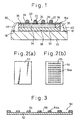
- Fig. 1 is a cross-sectional view showing an arrangement of an embodiment of a semiconductor device of the present invention.
- reference numeral 10 is a semiconductor element
- reference numeral 18 is an electrode provided on an electrode forming face of the semiconductor element 10.
- Reference numeral 30 is a wiring board for electrically connecting the electrode 18 with an external connecting terminal 22. This wiring board 30 is made to adhere onto an electrode forming face of the semiconductor element 10.
- a main body of the wiring board 30 includes: a buffer layer 34 arranged in a region for supporting the external connecting terminal 22; a bonding support layer 36 arranged in a region for supporting a wire bonding section 16a of a wiring pattern 16; and a base support layer 38 for supporting all the lower faces of the buffer layer 34 and the bonding support layer 36.
- the electrodes 18 of the semiconductor element 10 are arranged in the periphery of the electrode forming face. Therefore, the wiring board 30 is mounted in a region inside the peripheral region in which the electrodes 18 are arranged on the electrode forming face of the semiconductor element 10, and the wire bonding sections 16a are arranged in the periphery of the wiring board 30. Accordingly, the bonding support layer 36 for supporting the wire bonding sections 16a is arranged in the periphery of the wiring board 30 in a frame-shape, and the buffer layer 34 is formed in a region inside the bonding support layer 36.
- One end of the wiring pattern 16 is formed at the land 24 joined to the external connecting terminal 22, and the end of the wiring pattern 16 is formed at the wire bonding section 16a.
- the lands 24 are arranged in the region of the buffer layer 34, and the wiring pattern 16 is drawn out from the lands 24 to the periphery of the wiring board 30 and formed at the wire bonding sections 16a.
- Reference numeral 39 is a protective film for covering and protecting a surface of the wiring board 30. However, the lands 24 and the wire bonding sections 16a are exposed from the protective film 39.
- the semiconductor device of this embodiment is characterized in that the wiring pattern 16 on the wiring board 30 is electrically connected with the electrodes 18 of the semiconductor element 10 by the method of wire bonding.
- Reference numeral 40 is a bonding wire for electrically connecting the wire bonding section 16a of the wiring pattern 16 with the electrode 18 of the semiconductor element 10.
- the bonding support layer 36 is made of material having a predetermined elastic modulus so that wire bonding can be assuredly accomplished; for example, the bonding support layer 36 is made of a film of polyimide.
- the base support layer 38 is made of a film of polyimide having a predetermined elastic modulus.
- Resin 80 for sealing the bonding wires 40 is not necessarily flexible, i.e. resin 80 may be the same material as that composing the bonding support layer 36 and the base support layer 38.
- the buffer layer 34 is provided in order to reduce the thermal stress generated between the semiconductor element 10 and the mounting board when the semiconductor device is mounted on the mounting board. Therefore, the buffer layer 34 is made of flexible material having a predetermined low elastic modulus. When the external connecting terminals 22 are supported by the buffer layer 34, it becomes possible to significantly reduce the thermal stress generated when the semiconductor device is mounted on the mounting board.
- the wiring board 30 of the semiconductor device of this embodiment is composed as described above, the wire bonding sections 16a and the bonding wires are bonded to each other in a satisfactory state. Therefore, it becomes possible to easily connect the wiring pattern 16 with the electrode 18 of the semiconductor element 10 by the method of wire bonding. According to this connecting method of wire bonding, connecting can be conducted more easily and stably than the conventional connecting method of lead bonding. When the method of wire bonding, which is commonly used, is adopted, it becomes possible to conduct working effectively and the manufacturing cost can be decreased.
- Figs. 2(a), 2(b) and 3 are views showing a method of making a support sheet 50 having a bonding support sheet 36 and base support sheet 38 by using a base sheet 52 and frame-shaped sheet 54.
- Fig. 2(a) is a view showing the base sheet 52 which becomes the base support sheet 38.
- the base sheet 52 is a flat sheet made of a film of elastic material.
- Fig. 2(b) is a view showing the frame-shaped sheet 54 which becomes the bonding support sheet 36.
- through-holes 55 of a predetermined shape are formed for making cavities which become the buffer layer 34.
- Fig. 3 is a cross-sectional view of the support sheet 50 formed when the frame-shaped sheet 54 is made to adhere onto the base sheet 52. On one of the faces of the support sheet 50, cavities 56 are formed being partitioned by the partitioning section 54a of the frame-shaped sheet 54.
- Each region partitioned by the partitioning section 54a of the frame-shaped sheet 54 becomes one wiring board 30.
- the wiring boards 30 can be satisfactorily provided.
- the present invention is not limited to this specific method, by which the support sheet 50 is formed when the frame-shaped sheet 54 is made to adhere onto the base sheet 52. It is possible to form the support sheet 50 having the cavities 56 shown in Fig. 3 by the method of integral molding. In this case, the bonding support layer 36 and the base support layer 38 are integrally formed on the wiring board 30. The bonding support layer 36 is formed integrally with the base support layer 38 as described above.
- the elastic modulus of the base sheet 52 and that of the frame-shaped sheet 54 must be a predetermined value. Usually, in order to obtain an excellent state of wire bonding, it is sufficient that the Young's modulus of the base sheet 52 and that of the frame-shaped sheet 54 be approximately 4 GPa at room temperature.
- Examples of the material of the base sheet 52 and the frame-shaped sheet 54 having the aforementioned elastic modulus are: resins such as polyimide resin, epoxy resin and PPE; and glass cloth and no-woven fabric of high polymer impregnated with the above resins. It is also possible to use metal such as copper, nickel, alloy of Fe-Ni, and it is further possible to use ceramics such as alumina and aluminum nitride.
- Figs. 4(a) and 4(b) are views showing a process of making a sheet of copper foil 60 adhere onto the support sheet 50 by using an adhesive sheet 58.
- one cavity 56 on the support sheet 50 is shown enlarged.
- the sheet of copper foil 60 is actually made to adhere onto the entire face of the support sheet 50.
- the adhesive sheet 58 is placed on the support sheet 50, and the sheet of copper foil 60 is placed on the adhesive sheet 58, and then all of the layers are pressed so that they become joined to each other. Due to the pressing operation, material of the adhesive sheet 58 fills the cavity 56, so that the buffer layer 34 is formed, and at the same time, the sheet of copper foil 60 is made to adhere onto the buffer layer 34 and the support sheet 50.
- the adhesive sheet 58 is made of material the elastic modulus of which is low, such as NBR, or epoxy resin or acrylic resin in which material the elastic modulus of which is low is dispersed. Further, the adhesive sheet 58 is made of rubber material of polyolefin, silicon or fluorine. Concerning the material of the buffer layer 34, the elastic modulus of which is low, it is preferable to use material the Young's modulus of which is not higher than 1 GPa at 30°C.
- the adhesive sheet 58 of predetermined thickness is used so that the cavities 56 are filled with the adhesive sheet 58.
- the depth of the cavity 56 was about 100 ⁇ m.
- a thermoplastic sheet (the Young's modulus was about 400 MPa at 30°C and about 3 MPa at 150°C) of epoxy of about 120 ⁇ m thickness was used for the adhesive sheet 58.
- Concerning the sheet of copper foil 60 a sheet of electrolytic copper foil of 18 ⁇ m thickness was used, heated and pressurized, i.e. it was cured and integrated into a single body at 150°C for 2 hours.
- Fig. 4(b) is a view showing a state in which the sheet of copper foil 60 is made to integrally adhere onto the support sheet 50.
- the copper foil 60 is supported by the support sheet 50 via the buffer layer 34 filled with the material of the adhesive sheet 58.
- the sheet of copper foil 60 is made to adhere via the adhesive layer 58a.
- the adhesive layer 58a is a thin adhesive layer the thickness of which is 20 to 30 ⁇ m, which is left after the adhesive sheet 58 has been heated and pressurized. Since the thickness of the adhesive layer 58a is small, no problems are caused by its buffer action in the process of wire bonding.
- Fig. 5(a) is a view showing a state of forming a resist pattern 62 on which a surface of the sheet of copper foil 60 is coated with resist so as to coat a portion on which the wiring pattern 16 is formed.
- photosensitive solder resist is coated on the entire surface including the wiring pattern 16. Then, exposure and development are carried out. In this way, a protective film 39 from which only the lands 24 and the wire bonding section 16a are exposed can be formed as shown in Fig. 5(c).
- the wiring pattern 16 When the wiring pattern 16 is designed, consideration must be given to the land 24 being displaced on the plane direction (direction X - Y) and also in the thickness direction (direction Z). Therefore, it is preferable that the wiring pattern 16 not be designed having a linear shape, but having a curved shape so that it can be displaced in directions X - Y and Z.
- protective plating such as nickel plating or gold plating may be conducted on the surfaces of the land 24 and the wire bonding sections 16a.
- the large size support sheet 50 is divided into pieces by the partitioning section 54a, it is possible to provide a wiring board 30 the lands 24 of which are supported by the buffer layer 34 and the wire bonding sections 16a of which are supported by the bonding support layer 36.
- the bonding support layer 36 and the buffer layer 34 are supported by the base support layer 38.
- the support sheet 50 composed of the base sheet 52 and frame-shaped sheet 54 is made of material the elastic modulus of which is high, it is possible to maintain the profile of the support sheet 50, which is advantageous when it is being handled and transported.
- the method of manufacturing the wiring board 30 is not limited to the above specific method in which the sheet of copper foil 60 is made to adhere by using the adhesive sheet 58 simultaneously when the cavities 56 are filled.
- the following method may also be adopted.
- the cavities 56 are filled with buffer material such as resin which becomes the buffer layer 34 by the method of coating.
- a conductive layer such as a copper layer is formed on the surfaces of the buffer layer 34 and the bonding support layer 36 by means of spattering, and etching is conducted on this conductive layer so that the wiring pattern 16 having the predetermined lands 24 and the wire bonding sections 16a can be formed.
- the semiconductor device is manufactured as follows by using the above wiring board 30.
- the wiring board 30 is mounted when the base support layer 38 is made to adhere onto the electrode forming face of the semiconductor element 10.
- the wire bonding sections 16a are connected with the electrodes of the semiconductor element 10 by the method of wire bonding.
- the bonding wires 40 are sealed by the method of potting, and the external connecting terminals 22 such as solder balls are joined to the lands 24.
- an adhesive film may be previously made to adhere onto the bottom face of the wiring board 30, or alternatively before the large size support sheet 50 is divided into the wiring boards 30, an adhesive film may be made to adhere onto the back face of the support sheet 50 so as to provide a wiring board 30 having the adhesive film on it.
- the semiconductor device is formed such that the wiring board 30 is mounted on the semiconductor element 10 in which the electrodes 18 are arranged in the periphery of the electrode forming face.
- the electrodes 18 can be arranged on the central side of the electrode forming face.
- Fig. 6 is a view showing an example in which the electrodes 18 are arranged on the central side of the electrode forming face.
- the electrodes 18 and the wiring pattern 16 on the wiring board 30 are connected with each other by the method of wire bonding, and the lands 24 are connected with the external connecting terminals 22 so as to compose the semiconductor device.
- wire bonding can be conducted in a satisfactory manner. After wire bonding has been conducted between the electrodes 18 and the bonding sections 16a, the bonding wires 40 and the electrodes 18 are sealed by the method of potting so as to compose the semiconductor device.
- the configuration of the wiring board 30 is designed according to the arrangement positions of the electrodes 18 on the electrode forming face of the semiconductor element 10, it becomes possible to provide semiconductor devices for various semiconductor elements 10.
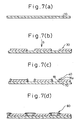
- Figs. 7(a) to 7(g) are views showing a method of manufacturing a semiconductor device of the present invention, in which the wiring board 30 is mounted on a semiconductor wafer 70.
- the semiconductor device is provided wherein the individual pieces of wiring boards 30 are mounted on the semiconductor element 10 which has been divided into individual chips.
- the wiring board 30 is mounted on a semiconductor wafer 70 and divided into individual pieces.
- a plurality of semiconductor chips 10 are formed on the semiconductor wafer 70 shown in Fig. 7(a).
- a plurality of electrodes 18 are formed along the periphery on the electrode forming face (the upper face in the drawing).
- the wiring board 30 which has been formed as described above is previously cut into individual pieces. Each wiring board 30 is positioned and mounted at the center of the electrode forming face of each semiconductor chip 10, i.e. each wiring board 30 is mounted inside the electrode 18 as shown in Fig. 7(b).
- each wiring board 30, which has been cut into an individual piece, has a structure as shown in Fig. 5(c).
- Fig. 8 is a plan view showing a state in which each wiring board 30 is mounted on the semiconductor wafer 70, wherein this plan view is taken in the direction of arrow B.
- the electrode 18 of the semiconductor chip 10 formed on the semiconductor wafer 70 is connected with the wire bonding section 16a of the wiring board 30 by the wire 40, using the method of wire bonding as shown in Fig. 7(c).
- the bonded portion is sealed by potting resin 80, i.e. the region, which includes the electrode 18 of the semiconductor chip 10, the bonding wire 40 and the bonding section 16a of the wiring pattern 16, is sealed by potting resin 80 as shown in Fig. 7(d). In this case, resin sealing is conducted over the entirety of the adjacent chip and wiring board 30.
- the resin sealing portion 80 of the semiconductor wafer 70 is cut along cutting line A as shown in Fig. 7(f) so that it can be separated into individual pieces. In this way, the individual semiconductor devices can be provided as shown in Fig. 7(g).
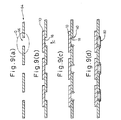
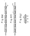
- Figs. 9(a) to 9(g) are views showing a method of manufacturing a semiconductor device of the present invention, in which the individual semiconductor chips 10 are mounted on the large size wiring board 64 having the openings 66.
- the peripheries of the openings 66 of the large size wiring board 64 are composed as shown in Fig. 11.
- the embodiment shown in these drawings has the same structure as that of the wiring board to obtain the semiconductor device shown in Fig. 6.
- Fig. 9(a) is a view showing this large size wiring board 64.
- the rectangular openings 66 are arranged in a grid-pattern.
- the individual semiconductor chips 10, the openings 66 of which are larger, are mounted on the openings 66 of the large size wiring board 64 so that the plurality of electrodes 18 can be located inside the openings 66 as shown in Fig. 9(b).
- the adhesive layer 32 shown in Fig. 1 in the sane manner as that of the embodiment described before.
- Fig. 10 is a plan view showing an arrangement of the electrodes of the semiconductor chips, wherein the view is taken in the direction of arrow C.
- the electrode 18 is formed at the center of the electrode forming face of the semiconductor chip 10 in this embodiment.
- the bonded portion is sealed by potting resin 80, i.e. the central region of the semiconductor chip 10, which includes the electrode 18 of the semiconductor chip, the bonding wire 40 and the wire bonding 16a of the wiring pattern 16, is sealed by potting resin 80 as shown in Fig. 9(d).
- potting resin 80 i.e. the central region of the semiconductor chip 10, which includes the electrode 18 of the semiconductor chip, the bonding wire 40 and the wire bonding 16a of the wiring pattern 16 is sealed by potting resin 80 as shown in Fig. 9(d).
- a solder ball 22, which is an external connecting terminal is joined to the land 24 of the wiring board 64 as shown in Fig. 9(e).
- the large size wiring board 64 is cut at a predetermined position between the adjacent semiconductor chips 10 along cutting line A as shown in Fig. 9(f) so as to obtain the individual wiring boards 30. In this way, each piece of semiconductor device can be provided as shown in Fig. 9(g).
- the wiring board and the semiconductor device of the present invention it is possible to connect the wiring pattern with the electrodes of the semiconductor element by the method of wire bonding. Therefore, the connecting operation can be conducted easily and effectively. By virtue of this, productivity can be enhanced. By virtue of the above structure, the thermal stress can be significantly reduced in the process of mounting. Accordingly, the present invention can provide a highly reliable product. According to the method of manufacturing the wiring board and the semiconductor device of the present invention, it is possible to manufacture the wiring board easily and effectively, and the thermal stress acting on the external connecting terminal can be greatly reduced in the process of mounting. Therefore, the present invention can provide a semiconductor device which is a highly reliable product. As described above, the industrial possibilities of the present invention are excellent.
Landscapes
- Engineering & Computer Science (AREA)
- Microelectronics & Electronic Packaging (AREA)
- Computer Hardware Design (AREA)
- Power Engineering (AREA)
- Physics & Mathematics (AREA)
- Condensed Matter Physics & Semiconductors (AREA)
- General Physics & Mathematics (AREA)
- Wire Bonding (AREA)
Applications Claiming Priority (4)
| Application Number | Priority Date | Filing Date | Title |
|---|---|---|---|
| JP21885198 | 1998-08-03 | ||
| JP21885198 | 1998-08-03 | ||
| PCT/JP1999/004169 WO2000008685A1 (fr) | 1998-08-03 | 1999-08-03 | Substrat de cablage, son procede de fabrication, et dispositif a semiconducteur |
| US09/539,117 US6455786B1 (en) | 1998-08-03 | 2000-03-30 | Wiring board and manufacturing method thereof and semiconductor device |
Publications (2)
| Publication Number | Publication Date |
|---|---|
| EP1035577A1 true EP1035577A1 (de) | 2000-09-13 |
| EP1035577A4 EP1035577A4 (de) | 2006-04-19 |
Family
ID=26522783
Family Applications (1)
| Application Number | Title | Priority Date | Filing Date |
|---|---|---|---|
| EP99933238A Withdrawn EP1035577A4 (de) | 1998-08-03 | 1999-08-03 | Verdrahtungssubstrat, seine herstellung und halbleitesvorrichtung |
Country Status (3)
| Country | Link |
|---|---|
| US (1) | US6455786B1 (de) |
| EP (1) | EP1035577A4 (de) |
| WO (1) | WO2000008685A1 (de) |
Families Citing this family (7)
| Publication number | Priority date | Publication date | Assignee | Title |
|---|---|---|---|---|
| TW536764B (en) * | 2002-04-30 | 2003-06-11 | Walsin Advanced Electronics | Method for multi-chip package and structure thereof |
| DE10250778B3 (de) * | 2002-10-30 | 2004-03-04 | Infineon Technologies Ag | Elektronisches Bauteil mit einem Halbleiterchip und Verfahren zum Bestücken eines Schaltungsträgers beim Herstellen des elektronischen Bauteils |
| JP2005234683A (ja) * | 2004-02-17 | 2005-09-02 | Matsushita Electric Ind Co Ltd | Icカード |
| WO2006103962A1 (ja) * | 2005-03-25 | 2006-10-05 | Sumitomo Bakelite Co., Ltd. | 半導体装置、並びにバッファーコート用樹脂組成物、ダイボンド用樹脂組成物、及び封止用樹脂組成物 |
| JP4068628B2 (ja) * | 2005-05-30 | 2008-03-26 | 松下電器産業株式会社 | 配線基板、半導体装置および表示モジュール |
| KR20090042574A (ko) * | 2007-10-26 | 2009-04-30 | 삼성전자주식회사 | 반도체 모듈 및 이를 구비하는 전자 장치 |
| CN114980492A (zh) * | 2022-06-28 | 2022-08-30 | 昆山国显光电有限公司 | 线路板组件、显示屏及电子设备 |
Citations (4)
| Publication number | Priority date | Publication date | Assignee | Title |
|---|---|---|---|---|
| US5148265A (en) * | 1990-09-24 | 1992-09-15 | Ist Associates, Inc. | Semiconductor chip assemblies with fan-in leads |
| WO1997011588A1 (en) * | 1995-09-18 | 1997-03-27 | Tessera, Inc. | Microelectronic lead structures with dielectric layers |
| WO1998025302A1 (fr) * | 1996-12-04 | 1998-06-11 | Shinko Electric Industries Co., Ltd. | Dispositif a semi-conducteurs obture a la resine, fabrication dudit dispositif |
| US5776796A (en) * | 1994-05-19 | 1998-07-07 | Tessera, Inc. | Method of encapsulating a semiconductor package |
Family Cites Families (10)
| Publication number | Priority date | Publication date | Assignee | Title |
|---|---|---|---|---|
| JPH09219463A (ja) * | 1996-02-08 | 1997-08-19 | Shinko Electric Ind Co Ltd | 半導体装置 |
| SG60099A1 (en) * | 1996-08-16 | 1999-02-22 | Sony Corp | Semiconductor package and manufacturing method of lead frame |
| JP2917932B2 (ja) * | 1996-09-24 | 1999-07-12 | ソニー株式会社 | 半導体パッケージ |
| JP3208072B2 (ja) * | 1996-09-30 | 2001-09-10 | 株式会社日立製作所 | 配線基板とそれを用いた半導体装置 |
| JPH10178145A (ja) * | 1996-12-19 | 1998-06-30 | Texas Instr Japan Ltd | 半導体装置及びその製造方法並びに半導体装置用絶縁基板 |
| US6249046B1 (en) * | 1997-02-13 | 2001-06-19 | Seiko Epson Corporation | Semiconductor device and method for manufacturing and mounting thereof, and circuit board mounted with the semiconductor device |
| JP3351706B2 (ja) * | 1997-05-14 | 2002-12-03 | 株式会社東芝 | 半導体装置およびその製造方法 |
| US6204564B1 (en) * | 1997-11-21 | 2001-03-20 | Rohm Co., Ltd. | Semiconductor device and method for making the same |
| JP3481117B2 (ja) * | 1998-02-25 | 2003-12-22 | 富士通株式会社 | 半導体装置及びその製造方法 |
| JP3526788B2 (ja) * | 1999-07-01 | 2004-05-17 | 沖電気工業株式会社 | 半導体装置の製造方法 |
-
1999
- 1999-08-03 EP EP99933238A patent/EP1035577A4/de not_active Withdrawn
- 1999-08-03 WO PCT/JP1999/004169 patent/WO2000008685A1/ja not_active Application Discontinuation
-
2000
- 2000-03-30 US US09/539,117 patent/US6455786B1/en not_active Expired - Lifetime
Patent Citations (4)
| Publication number | Priority date | Publication date | Assignee | Title |
|---|---|---|---|---|
| US5148265A (en) * | 1990-09-24 | 1992-09-15 | Ist Associates, Inc. | Semiconductor chip assemblies with fan-in leads |
| US5776796A (en) * | 1994-05-19 | 1998-07-07 | Tessera, Inc. | Method of encapsulating a semiconductor package |
| WO1997011588A1 (en) * | 1995-09-18 | 1997-03-27 | Tessera, Inc. | Microelectronic lead structures with dielectric layers |
| WO1998025302A1 (fr) * | 1996-12-04 | 1998-06-11 | Shinko Electric Industries Co., Ltd. | Dispositif a semi-conducteurs obture a la resine, fabrication dudit dispositif |
Non-Patent Citations (2)
| Title |
|---|
| PATENT ABSTRACTS OF JAPAN vol. 1998, no. 09, 31 July 1998 (1998-07-31) -& JP 10 098149 A (SONY CORP), 14 April 1998 (1998-04-14) * |
| See also references of WO0008685A1 * |
Also Published As
| Publication number | Publication date |
|---|---|
| US6455786B1 (en) | 2002-09-24 |
| EP1035577A4 (de) | 2006-04-19 |
| WO2000008685A1 (fr) | 2000-02-17 |
Similar Documents
| Publication | Publication Date | Title |
|---|---|---|
| US6388340B2 (en) | Compliant semiconductor chip package with fan-out leads and method of making same | |
| US6124637A (en) | Carrier strip and molded flex circuit ball grid array and method of making | |
| US6734552B2 (en) | Enhanced thermal dissipation integrated circuit package | |
| US5843808A (en) | Structure and method for automated assembly of a tab grid array package | |
| CA2159242C (en) | Process for manufacturing semiconductor device and semiconductor wafer | |
| CA1108305A (en) | Electronic circuit device and method of making the same | |
| US6909178B2 (en) | Semiconductor device and method of manufacturing the same | |
| US7015072B2 (en) | Method of manufacturing an enhanced thermal dissipation integrated circuit package | |
| US6020629A (en) | Stacked semiconductor package and method of fabrication | |
| JP3063032B2 (ja) | ボ―ルグリッドアレイ型半導体パッケ―ジ及びその製造方法 | |
| US7115483B2 (en) | Stacked chip package having upper chip provided with trenches and method of manufacturing the same | |
| KR100198502B1 (ko) | 반도체장치 및 그 제조방법 | |
| EP0058068B1 (de) | Träger für integrierte Schaltungschips | |
| US4987474A (en) | Semiconductor device and method of manufacturing the same | |
| US7163846B2 (en) | Method for manufacturing circuit devices | |
| EP1189273A2 (de) | Halbleiterbauteil und seine Herstellung | |
| US7170153B2 (en) | Semiconductor device and its manufacturing method | |
| US6455786B1 (en) | Wiring board and manufacturing method thereof and semiconductor device | |
| KR20020030087A (ko) | 개선된 생산량의 반도체 패키지 디바이스를 제조하기 위한구조 및 방법 | |
| KR100658120B1 (ko) | 필름 기판을 사용한 반도체 장치 제조 방법 | |
| US20010010947A1 (en) | Film ball grid array (BGA) semiconductor package | |
| US6965162B2 (en) | Semiconductor chip mounting substrate and semiconductor device using it | |
| JP4131256B2 (ja) | 半導体装置及びその製造方法 | |
| KR100374661B1 (ko) | 배선 기판, 그 제조 방법 및 반도체 장치 | |
| KR19980068016A (ko) | 가요성(可撓性) 회로 기판을 이용한 볼 그리드 어레이(Ball Grid Array : BGA) 반도체 패키지 및 그 제조 방법 |
Legal Events
| Date | Code | Title | Description |
|---|---|---|---|
| PUAI | Public reference made under article 153(3) epc to a published international application that has entered the european phase |
Free format text: ORIGINAL CODE: 0009012 |
|
| 17P | Request for examination filed |
Effective date: 20000425 |
|
| AK | Designated contracting states |
Kind code of ref document: A1 Designated state(s): AT BE CH CY DE DK ES FI FR GB GR IE IT LI LU MC NL PT SE |
|
| RBV | Designated contracting states (corrected) |
Designated state(s): DE FR GB |
|
| A4 | Supplementary search report drawn up and despatched |
Effective date: 20060306 |
|
| STAA | Information on the status of an ep patent application or granted ep patent |
Free format text: STATUS: THE APPLICATION IS DEEMED TO BE WITHDRAWN |
|
| 18D | Application deemed to be withdrawn |
Effective date: 20060524 |