EP1035365B1 - Universalanschluss - Google Patents
Universalanschluss Download PDFInfo
- Publication number
- EP1035365B1 EP1035365B1 EP99104565A EP99104565A EP1035365B1 EP 1035365 B1 EP1035365 B1 EP 1035365B1 EP 99104565 A EP99104565 A EP 99104565A EP 99104565 A EP99104565 A EP 99104565A EP 1035365 B1 EP1035365 B1 EP 1035365B1
- Authority
- EP
- European Patent Office
- Prior art keywords
- valve
- universal connection
- accordance
- valve housing
- connecting shaft
- Prior art date
- Legal status (The legal status is an assumption and is not a legal conclusion. Google has not performed a legal analysis and makes no representation as to the accuracy of the status listed.)
- Expired - Lifetime
Links
- 230000008878 coupling Effects 0.000 title description 26
- 238000010168 coupling process Methods 0.000 title description 26
- 238000005859 coupling reaction Methods 0.000 title description 26
- 230000001681 protective effect Effects 0.000 claims description 35
- 239000012530 fluid Substances 0.000 claims description 23
- 238000007789 sealing Methods 0.000 claims description 19
- 239000004033 plastic Substances 0.000 claims description 16
- 229910052751 metal Inorganic materials 0.000 claims description 14
- 239000002184 metal Substances 0.000 claims description 14
- 239000007788 liquid Substances 0.000 claims description 6
- 239000007789 gas Substances 0.000 claims description 5
- 239000005060 rubber Substances 0.000 claims description 4
- 229910010293 ceramic material Inorganic materials 0.000 claims 3
- 230000001105 regulatory effect Effects 0.000 claims 3
- 239000000463 material Substances 0.000 claims 2
- 238000000034 method Methods 0.000 abstract description 15
- 230000008569 process Effects 0.000 abstract description 14
- 239000000919 ceramic Substances 0.000 description 8
- 238000012360 testing method Methods 0.000 description 7
- 238000010438 heat treatment Methods 0.000 description 6
- 238000004519 manufacturing process Methods 0.000 description 5
- 238000009423 ventilation Methods 0.000 description 5
- 230000008901 benefit Effects 0.000 description 4
- 230000008859 change Effects 0.000 description 4
- 238000005259 measurement Methods 0.000 description 4
- 229920000642 polymer Polymers 0.000 description 4
- 238000009529 body temperature measurement Methods 0.000 description 3
- 230000006378 damage Effects 0.000 description 3
- 238000011161 development Methods 0.000 description 3
- 238000003825 pressing Methods 0.000 description 3
- XLYOFNOQVPJJNP-UHFFFAOYSA-N water Substances O XLYOFNOQVPJJNP-UHFFFAOYSA-N 0.000 description 3
- 230000006978 adaptation Effects 0.000 description 2
- 238000006073 displacement reaction Methods 0.000 description 2
- 238000012423 maintenance Methods 0.000 description 2
- 238000013022 venting Methods 0.000 description 2
- 241001136792 Alle Species 0.000 description 1
- 241000237942 Conidae Species 0.000 description 1
- LFQSCWFLJHTTHZ-UHFFFAOYSA-N Ethanol Chemical compound CCO LFQSCWFLJHTTHZ-UHFFFAOYSA-N 0.000 description 1
- 208000027418 Wounds and injury Diseases 0.000 description 1
- 238000009530 blood pressure measurement Methods 0.000 description 1
- 238000011109 contamination Methods 0.000 description 1
- 238000005516 engineering process Methods 0.000 description 1
- 238000003912 environmental pollution Methods 0.000 description 1
- 210000003746 feather Anatomy 0.000 description 1
- 239000000383 hazardous chemical Substances 0.000 description 1
- 238000007654 immersion Methods 0.000 description 1
- 208000014674 injury Diseases 0.000 description 1
- 238000009434 installation Methods 0.000 description 1
- 230000003993 interaction Effects 0.000 description 1
- 230000007246 mechanism Effects 0.000 description 1
- QSHDDOUJBYECFT-UHFFFAOYSA-N mercury Chemical compound [Hg] QSHDDOUJBYECFT-UHFFFAOYSA-N 0.000 description 1
- 229910052753 mercury Inorganic materials 0.000 description 1
- 210000002445 nipple Anatomy 0.000 description 1
- 230000000149 penetrating effect Effects 0.000 description 1
- 230000008439 repair process Effects 0.000 description 1
- 230000000717 retained effect Effects 0.000 description 1
- 238000009420 retrofitting Methods 0.000 description 1
- 238000005070 sampling Methods 0.000 description 1
- 238000005476 soldering Methods 0.000 description 1
- 229910001220 stainless steel Inorganic materials 0.000 description 1
- 239000010935 stainless steel Substances 0.000 description 1
- 230000007704 transition Effects 0.000 description 1
- 238000013519 translation Methods 0.000 description 1
Images





Classifications
-
- F—MECHANICAL ENGINEERING; LIGHTING; HEATING; WEAPONS; BLASTING
- F16—ENGINEERING ELEMENTS AND UNITS; GENERAL MEASURES FOR PRODUCING AND MAINTAINING EFFECTIVE FUNCTIONING OF MACHINES OR INSTALLATIONS; THERMAL INSULATION IN GENERAL
- F16L—PIPES; JOINTS OR FITTINGS FOR PIPES; SUPPORTS FOR PIPES, CABLES OR PROTECTIVE TUBING; MEANS FOR THERMAL INSULATION IN GENERAL
- F16L29/00—Joints with fluid cut-off means
- F16L29/02—Joints with fluid cut-off means with a cut-off device in one of the two pipe ends, the cut-off device being automatically opened when the coupling is applied
Definitions
- the known systems have in common that the seals in the bore of the coupling sleeve of the valve housing are. This has several disadvantages. That's how they are Seals in the coupling bush not visible or visible, so that their condition cannot be controlled. This results in the risk that the valve without an early Detect can become unusable. A repair by replacing the seal is not possible, so that in in most cases the entire valve has to be replaced, with the further disadvantage of lowering the pressure or stopping of the entire system or a corresponding part thereof.
- the invention has for its object this significant To avoid disadvantage of the known systems.
- valve body designed as a cone or ball consists of Metal, but it can also be made of rubber, plastic or ceramic consist.
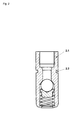
- Figure 1a shows a longitudinal section through a valve housing 1.12 a universal connection according to the invention for recording a spherical valve body 1.7 and a spring plate 1.9 to support the valve body 1.7 against the Coil spring 1.10.
- a protective cap in the case of Is not used or for screwing in a valve opener the screw-in thread is designed as an internal thread 1.1. This protects the thread. This is particularly advantageous because in most applications the Environment of the universal connection not against contamination is secured.
- an inner cone 1.2 is provided, which is also light Introduction of the valve opener with its outside Seal serves.
- a retaining tab of the protective cap To attach a retaining tab of the protective cap is a the circumference of the valve housing 1.12 guided groove 1.4 is provided. This makes the protective cap captive.
- one elastic seal 1.5 is provided, which in a groove is stored.
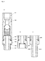
- connection mandrel Another groove in the lower area of the Connection mandrel is used to hold an easily replaceable and visible elastic seal 4.9.
- a cross channel 4.10 on the mandrel head ensures passage of the fluid 4.11, because the opening of the longitudinal channel during the opening process presses the valve body 1.7 and thus closes itself.
- the handwheel 4.4 is for easier handling with a Corrugation 4.5 provided, and for screwing the Valve opener in the valve housing 1.12 of the universal connection serves the thread 4.6, which is in the internal thread 1.1 of the Valve housing engages.
- the structure of this valve opener shows a number of advantages, to the following regardless of each Precedence of their importance is considered.
- the axial displacement of the connecting pin 4.8 in the valve housing 1.12 for The valve body 1.7 or 1.13 is opened solely by the actuation of the handwheel 4.4 via the thread 4.6 in Interaction with the inner winch 1.1 of the valve housing 1.12.
- the opening process can remain in any opening phase, so that a very precise throttling is possible.
- Regardless of the axial displacement of the connecting pin 4.8 is a rotary movement of the connection mandrel in every valve opening position 4.8 given. This possibility offers itself several advantages. Is, for example, with the thread 4.1 Hose connection connected, this is when closing and opening process is not twisted, but remains in its original location.
- the valve opener When directly connecting display instruments with The valve opener can display the instrument panel to anyone Time of the closing and opening state and thus also during of the entire company swiveled 360 ° in each direction so that optimal readability at all times, i.e. can also be produced during operation under system pressure. This is of great importance especially if only one there is little space for mounting and reading. This allows pipe laying with their connections Perform measurements or controls more optimally, since the readable positioning of measuring devices now is irrelevant and still changed during operation can be. If you only think of an ordinary one Boiler room according to the state of the art, so you can see that the scales of the various display instruments point in all possible directions, regardless of the incidence of light or readability.
- FIGS. b1 and b2 shown in three embodiments.
- a protective cap is shown in FIGS. b1 and b2 shown in three embodiments.
- Figure 5a is shown a two-part embodiment in which the cap 5.8 made of plastic or metal and the screw-in pin 5.1 can be made of metal or ceramic.
- the Sealing and screw-in pin 5.1 is equipped with a cone 5.9, which the cone 1.2 in the bore of the valve housing 1.12 is adjusted so that in the screwed state an additional seal and, in an emergency, an emergency seal is formed, e.g. B. in the event of a disaster in the event of a fire.
- the valve body (rubber or plastic ball or the seal on the cone) may be destroyed.
- Figure 5b1 shows a one-piece Version with retaining tab 5.4, similar to that in Figure 5a is shown, but which is completely made of plastic consists.
- FIG. 5b2 shows an embodiment similar to that according to Figure 5b1, but without a retaining tab 5.4.
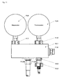
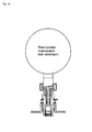
- FIG. 11 shows an application example of the invention under Use of a special measuring distributor adapted to the invention 11.1.
- the measuring distributor 11.1 is for one or more Measuring devices such as a thermometer 11.5 and a manometer 11.8, equipped with a vent or Filling port 11.6 are combined so that when Vent or fill a direct observation of the measured values is possible.
- the measuring devices 11.5 and 11.8 are each with a valve opener 11.4 or 11.7 connected.
- the connector 11.2 is used to connect a valve opener 11.2a Help of the handwheel 11.3 and the connector 11.2b to Connection of a connecting hose.
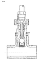
- FIG. 14 shows a further development of this temperature measurement method.
- the valve opener according to FIG Measuring distributor supplied which is designed such that in the assembled state, the temperature sensors in the liquid flow lies, so that the temperature is determined more precisely can be.
- the measuring distributor is by means of a valve opener with a universal connection, not shown connected to a fluidic system whose temperature increases monitor is.
Landscapes
- Engineering & Computer Science (AREA)
- General Engineering & Computer Science (AREA)
- Mechanical Engineering (AREA)
- Insulated Conductors (AREA)
- Exchange Systems With Centralized Control (AREA)
- Pivots And Pivotal Connections (AREA)
- Quick-Acting Or Multi-Walled Pipe Joints (AREA)
- Sliding Valves (AREA)
Description
- FIGUR 1a
- einen Längsschnitt durch ein Ventilgehäuse eines Universalanschlusses nach der Erfindung mit einem kugelförmigen Ventilkörper, zum Einschrauben;
- FIGUR 1b
- einen Längsschnitt durch ein Ventilgehäuse eines Universalanschlusses nach der Erfindung mit einem kegelförmigen Ventilkörper, zum Einschrauben;
- FIGUR 2
- einen Längsschnitt durch ein Ventilgehäuse eines Universalanschlusses nach der Erfindung, zum Einpressen;
- FIGUR 3
- Längsschnitte durch ein Ventilgehäuse eines Universalanschlusses nach der Erfindung mit wählbaren Anschlüssen a), b) und c);
- FIGUR 4
- einen Längsschnitt durch einen Ventilöffner für alle Universalanschlüsse nach der Erfindung, zum Einschrauben;
- FIGUR 5
- Längsschnitte durch drei Schutzkappen für Universalanschlüsse;
- a: zweiteilig, mit einem Dicht- und Einschraubzapfen aus Metall oder Keramik, mit Haltelasche;
- b1: einteilig, vollständig aus Kunststoff mit integriertem Einschraubzapfen aus Kunststoff, mit Haltelasche;
- b2: einteilig, vollständig aus Kunststoff mit integriertem Einschraubzapfen aus Kunststoff, ohne Haltelasche;
- FIGUR 6
- einen Längsschnitt durch einen Universalanschluß nach der Erfindung mit einem wählbaren Anschluß und einer aufgeschraubten einteiligen Schutzkappe mit Haltelasche;
- FIGUR 7
- einen Längsschnitt durch einen in ein Rohrsystem eingepreßten Universalanschluß mit aufgeschraubter einteiliger Schutzkappe;
- FIGUR 8
- einen Längsschnitt durch ein Ventilgehäuse eines mit einem Rohrsystem verschraubten Universalanschlusses, in der Einführungsphase des Ventilöffners;
- FIGUR 9
- einen Längsschnitt durch ein Ventilgehäuse eines mit einem Rohrsystem verschraubten Universalanschlusses nach Figur 8, in der Einführungsphase des Ventilöffners kurz vor der Öffnung des Ventilkörpers;
- FIGUR 10.
- einen Längsschnitt durch ein Ventilgehäuse eines mit einem Rohrsystem verschraubten Universal anschlusses nach Figur 8 oder 9, in der geöffneten Phase des Ventilkörpers;
- FIGUR 11.
- eine schematische Ansicht eines Meßverteilers mit zwei angeschlossenen Nutzungseinrichtungen;
- FIGUR 12.
- eine schematische Ansicht eines Universalanschlusses mit einer Nutzungseinrichtung z. B. mechanisches Thermometer;
- FIGUR 13.
- eine schematische Ansicht eines Ventilöffners z. B. mit einem elektrischen Temperaturfühler, und
- FIGUR 14.
- eine schematische Ansicht eines Meßverteilers, einfach, mit Nutzungseinrichtung z. B. als elektrischer Temperaturfühler.
| BEZUGSZEICHENLISTE | |
| Figur 1 | |
| Innengewinde | 1.1 |
| Innenkonus | 1.2 |
| Sechskant | 1.3 |
| Nut | 1.4 |
| Dichtung | 1.5 |
| Dichtfläche | 1.6 |
| Ventilkörpers | 1.7 |
| Außengewinde | 1.8 |
| Federteller | 1.9 |
| Spiralfeder | 1.10 |
| Bördelung | 1.11 |
| Ventilgehäuse | 1.12 |
| Figur 1b | |
| Dichtkopf | 1.13 |
| Dichtring | 1.14 |
| Figur 2 | |
| Ventilgehäuse | 2.1 |
| Nut | 2.2 |
| Figur 3a, b, c | |
| Ventilgehäuses | 3.1 |
| Nut | 3.2 |
| Anschlußstück | 3.3 |
| Dichtung | 3.4 |
| Sechskant | 3.5 |
| Dichtung | 3.6 |
| Außengewinde | 3.7 |
| Anschlußstück | 3.8 |
| Abdichtung | 3.9 |
| Innengewinde | 3.10 |
| Anschlußstück | 3.11 |
| Zylinder | 3.12 |
| Figur 4 | |
| Anschlußgewinde | 4.1 |
| Schlüsselfläche | 4.2 |
| Positionierung | 4.3 |
| Handrades | 4.4 |
| Riffelung | 4.5 |
| Gewinde | 4.6 |
| Nut | 4.7 |
| Anschlußdorn | 4.8 |
| Dichtung | 4.9 |
| Querkanal | 4.10 |
| Dornkopf | 4.11 |
| Figur 5 | |
| Einschraubzapfen | 5.1 |
| Sechskant | 5.2 |
| Nut für Haltelasche | 5.3 |
| Haltelasche | 5.4 |
| Sechskant | 5.5 |
| Riffelung | 5.6 |
| Gewinde | 5.7 |
| Kappe | 5.8 |
| Konus | 5.9 |
| Befestigungselement | 5.10 |
| Figur 11 | |
| Meßverteiler | 11.1 |
| Anschlußstück | 11.2 |
| Ventilöffner | 11.2a |
| Anschlußstück | 11.2b |
| Handrad | 11.3 |
| Ventilöffner | 11.4 |
| Termometer | 11.5 |
| Befüllungs- | |
| Entlüftungsschlauch | 11.6 |
| Ventilöffner | 11.7 |
| Manometer | 11.8 |
Claims (18)
- Universalanschluß zur Verbindung eines unter Druck stehenden Fluidsystems, welches auch für brennbare Gase und brennbare Flüssigkeiten verwendbar ist, mit Nutzungseinrichtungen zur Messung des Druckes und/oder der Temperatur, bestehend aus einem Ventil mit einem Ventilgehäuse (1.12), in dessen Bohrung ein selbstschließendes federbelastetes Rückschlagventil (1.7;1.13) angeordnet ist und einem mit diesem verbindbaren Ventilöffner, wobei der in der Bohrung des Ventilgehäuses angeordnete federbelastete Ventilkörper des Rückschlagventils beim Einschrauben des Ventilöffners (11.4) durch dessen Anschlußdorn (4.8) gegen den Federdruck axial in die Offenstellung des Ventils verschiebbar ist, und der Ventilöffner (11.4) als Adapter mit einem Handrad (4.4) mit Außengewinde (4.6) und einer zentralen Bohrung zur drehbaren Aufnahme des Anschlußdorns (4.8) ausgebildet ist, das Ventilgehäuse (1.12) eine Bohrung mit einem Innengewinde (1.1) zur lösbaren Befestigung des Handrades (4.4), mit einer sich anschließenden Gleitstrecke für den Anschlußdorn (4.8) des Ventilöffners aufweist, und der Anschlußdorn (4.8) mit einer zentralen Bohrung mit zentralen und/oder radialen Öffnungskanälen (4.10) in seinem Kopfteil (4.11) und eine an seiner Außenfläche zum Zwecke des Auswechselns zugänglich angeordnete Dichtung (4.9) versehen ist, welche mit der Gleitstrecke des Ventilgehäuses (1.12) dichtend zusammenwirkt, wobei die Strecke vom Beginn des Ventilöffnungsvorgangs bis zur vollen Öffnung des Ventilkörpers (1.7) so dimensioniert ist, dass eine einstellbare Drosselung des durchfließenden Volumenstromes gegeben ist und der Eingangsbereich der Gleitstrecke im Ventilgehäuse (1.12) im Anschluss an das Innengewinde (1.1) des Ventilgehäuses (1.12) eine Fläche für eine Sekundärabdichtung in Form eines Konus (1.2) aufweist.
- Universalanschluß nach Anspruch 1, dadurch gekennzeichnet, dass das Handrad (4.4) durch einen Haltering (4.7) in einer am Umfang des Anschlußdorns (4.8) befindlichen Nut drehbar befestigt ist, wobei der Anschlußdorn (4.8) mit dem Handrad (4.4) den Ventilöffner bilden und die freie Länge des An schlußdorns (4.8) derartig dimensioniert ist, dass der Öffnungsvorgang des Ventilkörpers (1.7) beim Einführen des Anschlußdorns (4.8) erst dann einleitbar ist, wenn sich die Dichtung (4-.-9) des An- schlußdorns (4.8) derartig in der Gleitstrecke der Bohrung des Ventilgehäuses befindet, dass das System nach außen hin gegen den Systemdruck mit einem Sichereitsfaktor vollständig abdichtet und das aus dem System her gegenwirkende Kräfte bereits von entsprechenden Gewindegängen gehalten werden.
- Universalanschluß nach Anspruch 1 oder 2, dadurch gekennzeichnet, daß der Anschlußdorn (4.8) an seinem äußeren Ende einen integrierten Sechskant (4.2) mit einem Innengewinde (4.1) zum Gegenhalten beim Anschluß von Nutzungseinrichtungen aufweist, der auch bei einem festgezogenen Handrad und damit einem geöffneten Ventilkörper (1.7) drehbar ist, so daß eine Nutzungseinrichtung in die gewünschte Ableseposition gedreht werden kann.
- Universalanschluß nach einem der voranstehenden Ansprüche, dadurch gekennzeichnet, dass der Öffnungs-, Drossel- und Schließvorgang des Ventilkörpers (1.7) durch den Schraub vorgang des Handrades (4.4) mit seinem Außengewindeteil (4.6) im Innengewinde (1.1) des Ventilgehäuses bewirkbar ist, wobei die Drehbewegung des Handrades (4.4) in eine axiale Bewegung des Anschlußdorns (4.8) in einem definierten Verhältnis über setzbar ist.
- Universalanschluß nach einem der voranstehenden Ansprüche dadurch gekennzeichnet, daß die Strecke vom Beginn des Ventilöffnungsvorganges bis zur vollen Öffnung des Ventilkörpers (1.7) so dimensioniert ist, daß eine einstellbare Drosselung des durchfließenden Volumenstromes gegeben ist.
- Universalanschluß nach einem der voranstehenden Ansprüche, dadurch gekennzeichnet, daß der Eingangsbereich der Bohrung im Ventilgehäuse (1.12) im Anschluß an das Innengewinde (1.1) des Ventilgehäuses (1.12) als Sekundärabdichtung in Form eines Konus (1.2) ausgebildet ist, die in Verbindung mit einer Schutz kappe wirksam wird.
- Universalanschluß nach einem der voranstehenden Ansprüche, dadurch gekennzeichnet, daß dasVentil bei Nichtgebrauch durch eine ein- oder mehrteilige Schutzkappe gesichert ist, welche einen Einschraubzapfen (5.1) mit Dichtkegel (5.9) aufweist.
- Universalanschluß nach Anspruch 7, dadurch gekennzeichnet, daß die zweiteilige Schutzkappe einen Einschraubzapfen (5.1) aus Metall oder Keramik aufweist.
- Universalanschluß nach Anspruch 7, dadurch gekennzeichnet, daß die Schutzkappe mit Einschraubzapfen einteilig ausgebildet ist und vollständig aus Kunststoff besteht.
- Universalanschluß nach Anspruch 7, dadurch gekennzeichnet, daß die Schutzkappe einen Einschraubzapfen (5.1) mit geschütz tem Außengewinde (5.7) aufweist.
- Universalanschluß nach Anspruch 7, dadurch gekennzeichnet, daß die Schutzkappe einen Sechskant (5.2) zum Festziehen derselben Z.B. als Kindersicherung aufweist.
- Universalanschluß nach einem der voranstehenden Ansprüche, dadurch gekennzeichnet, daß der Ventilöffner direkt oder über einen Verbindungsschlauch mit einer Nutzungseinrichtung verbindbar ist.
- Universalanschluß nach einem der voranstehenden Ansprüche, dadurch gekennzeichnet, daß der als Kugel oder Kegel ausgebildete Ventilkörper (1.7) aus Gummi, Kunststoff oder Keramik besteht.
- Universalanschluß nach einem der voranstehenden Ansprüche, dadurch gekennzeichnet, daß der Ventilkörper (1.7) gegen die Spiralfeder (1.10) durch einen Federteller (1.9) aus Metall, Keramik oder Kunststoff abgestützt ist, wobei der Federteller (1.9) zur Zentrierung einen Zapfen aufweist und als Notabdichtung wirksam ist.
- Universalanschluß nach einem der voranstehenden Ansprüche, dadurch gekennzeichnet, daß das Ventilgehäuse (2.1) als ein in genormte Rohrleitungsenden einpreßbarer Kreiszylinderkörper ausgebildet ist.
- Universalanschluß nach einem der Ansprüche 1-14, dadurch gekennzeichnet, daß das Ventilgehäuse (3.1) rohrsystemseitig ein Innengewinde zur Aufnahme eines Anschlußstückes aufweist, wobei das Anschlußstück an einem Ende ein Außengewinde und am anderen Ende ein Innengewinde, ein Außengewinde oder einen in ein Rohrende einpreßbaren Kreiszylindermantel aufweist.
- Universalanschluß nach einem der voranstehenden Ansprüche, dadurch gekennzeichnet, daß der Ventilöffner in der Bohrung des Anschlussdorns einen Temperatursensor aufweist.
- Universalanschluß nach einem der voranstehenden Ansprüche, dadurch gekennzeichnet, daß der Ventilöffner mit z. B. mechanischen, elektrischen oder anderen Nutzungseinrichtungen verbunden ist.
Priority Applications (4)
| Application Number | Priority Date | Filing Date | Title |
|---|---|---|---|
| AT99104565T ATE252702T1 (de) | 1999-03-08 | 1999-03-08 | Universalanschluss |
| EP99104565A EP1035365B1 (de) | 1999-03-08 | 1999-03-08 | Universalanschluss |
| DK99104565T DK1035365T3 (da) | 1999-03-08 | 1999-03-08 | Universalforbindelse |
| DE59907442T DE59907442D1 (de) | 1999-03-08 | 1999-03-08 | Universalanschluss |
Applications Claiming Priority (1)
| Application Number | Priority Date | Filing Date | Title |
|---|---|---|---|
| EP99104565A EP1035365B1 (de) | 1999-03-08 | 1999-03-08 | Universalanschluss |
Publications (2)
| Publication Number | Publication Date |
|---|---|
| EP1035365A1 EP1035365A1 (de) | 2000-09-13 |
| EP1035365B1 true EP1035365B1 (de) | 2003-10-22 |
Family
ID=8237720
Family Applications (1)
| Application Number | Title | Priority Date | Filing Date |
|---|---|---|---|
| EP99104565A Expired - Lifetime EP1035365B1 (de) | 1999-03-08 | 1999-03-08 | Universalanschluss |
Country Status (4)
| Country | Link |
|---|---|
| EP (1) | EP1035365B1 (de) |
| AT (1) | ATE252702T1 (de) |
| DE (1) | DE59907442D1 (de) |
| DK (1) | DK1035365T3 (de) |
Cited By (4)
| Publication number | Priority date | Publication date | Assignee | Title |
|---|---|---|---|---|
| USD518559S1 (en) | 2004-07-07 | 2006-04-04 | Vetco Aibel As | Seal |
| US7871110B2 (en) | 2003-07-21 | 2011-01-18 | Vetco Gray Scandinavia As | Sealing element and a coupling device and a valve device provided with such a sealing element |
| EP4498003A1 (de) | 2023-07-27 | 2025-01-29 | Vaillant GmbH | Gasleckagebewältigung |
| EP4559552A1 (de) | 2023-11-21 | 2025-05-28 | Vaillant GmbH | Gas-flüssig-zyklonabscheider |
Families Citing this family (8)
| Publication number | Priority date | Publication date | Assignee | Title |
|---|---|---|---|---|
| TWI273167B (en) * | 2004-12-15 | 2007-02-11 | Topeak Inc | Improved structure of high-pressure gas-filling joint |
| DE202008005416U1 (de) | 2008-04-11 | 2008-07-10 | E + E Elektronik Ges.M.B.H. | Anschlussbaueinheit |
| DE202009013793U1 (de) | 2009-10-06 | 2010-02-18 | Wilhelm Schauerte Gmbh & Co. Kg | Be- und Entlüftungsautomat mit Membran als Systembaukasten |
| EP2309162A3 (de) | 2009-10-06 | 2014-05-21 | Wilhelm Schauerte GmbH & Co. KG Geschäftsführung | Be- und Entlüftungsautomat mit Membran als Systembaukasten |
| DE202010009634U1 (de) | 2010-06-17 | 2010-09-30 | Wilhelm Schauerte Gmbh & Co. Kg | Be- und Entlüftungsautomat mit Membran als Systembaukasten 2 |
| DE202010015974U1 (de) | 2010-11-22 | 2011-03-17 | Wilhelm Schauerte Gmbh & Co. Kg | Be-/Entlüftungsautomat mit Elastomer-Membran |
| DE102020102277B4 (de) | 2020-01-30 | 2022-07-21 | Hydrotechnik Gesellschaft mit beschränkter Haftung | Fluidanschluss, umfassend eine Anschlussarmatur und eine Ventil- und/oder Messkupplung für fluidische Systeme zur Erfassung von Arbeitsdrücken von fluidischen Medien |
| DE102020209735A1 (de) * | 2020-08-03 | 2022-02-03 | Argo Gmbh | System zum fluidführenden Verbinden eines Elements mit einem Gegenstück, Adapterelement sowie Adaptergehäuse zum fluidführenden Verbinden sowie Adaptersystem aufweisend das Adapterelement sowie das Adaptergehäuse |
Family Cites Families (5)
| Publication number | Priority date | Publication date | Assignee | Title |
|---|---|---|---|---|
| US2524052A (en) * | 1946-09-23 | 1950-10-03 | Specialties Dev Corp | Valve |
| DE2641271C3 (de) | 1976-09-14 | 1979-10-25 | Hydrotechnik Gmbh, 6052 Muehlheim | Kupplung zum Herstellen eines Anschlusses an ein unter Druck stehendes System |
| DE2756084C3 (de) * | 1977-12-16 | 1980-06-26 | Hydrotechnik Gmbh, 6052 Muehlheim | Schraubsicherung |
| GB2019533B (en) * | 1978-04-21 | 1982-09-29 | Crane Ltd | Pressure tapping valve unit |
| DE3341860C2 (de) | 1983-11-19 | 1985-09-19 | Hydrotechnik Gmbh, 6250 Limburg | Meßkupplung für fluidische Systeme |
-
1999
- 1999-03-08 DE DE59907442T patent/DE59907442D1/de not_active Expired - Lifetime
- 1999-03-08 AT AT99104565T patent/ATE252702T1/de not_active IP Right Cessation
- 1999-03-08 EP EP99104565A patent/EP1035365B1/de not_active Expired - Lifetime
- 1999-03-08 DK DK99104565T patent/DK1035365T3/da active
Cited By (6)
| Publication number | Priority date | Publication date | Assignee | Title |
|---|---|---|---|---|
| US7871110B2 (en) | 2003-07-21 | 2011-01-18 | Vetco Gray Scandinavia As | Sealing element and a coupling device and a valve device provided with such a sealing element |
| US8616586B2 (en) | 2003-07-21 | 2013-12-31 | Vetco Gray Scandinavia As | Valve device provided with a sealing element |
| USD518559S1 (en) | 2004-07-07 | 2006-04-04 | Vetco Aibel As | Seal |
| EP4498003A1 (de) | 2023-07-27 | 2025-01-29 | Vaillant GmbH | Gasleckagebewältigung |
| DE102023119984A1 (de) | 2023-07-27 | 2025-01-30 | Vaillant Gmbh | Gasleckagebewältigung |
| EP4559552A1 (de) | 2023-11-21 | 2025-05-28 | Vaillant GmbH | Gas-flüssig-zyklonabscheider |
Also Published As
| Publication number | Publication date |
|---|---|
| ATE252702T1 (de) | 2003-11-15 |
| DE59907442D1 (de) | 2003-11-27 |
| EP1035365A1 (de) | 2000-09-13 |
| DK1035365T3 (da) | 2004-02-23 |
Similar Documents
| Publication | Publication Date | Title |
|---|---|---|
| EP1035365B1 (de) | Universalanschluss | |
| DE69011769T2 (de) | Schnellkupplung. | |
| DE3508570C2 (de) | ||
| EP1649201B2 (de) | Mehrwegeventil | |
| DE19529197A1 (de) | Entleerventil | |
| DE3700473C1 (en) | Wall lead-through | |
| DE102014218151B4 (de) | Sicherungsvorrichtung | |
| DE60121560T2 (de) | Kartusche für ventil | |
| DE102005006971B3 (de) | Adapter für die Verbindung eines Gasverbrauchers mit einer Druckgasflasche | |
| EP2416138B1 (de) | Messanordnung und eine Vorrichtung zum Anordnen eines Temperatursensors in einem Messraum | |
| EP0811799B1 (de) | Ventil-Anbohrarmatur für vorzugsweise unter Mediendruck stehende Versorgungsleitungen aus Kunststoff | |
| EP0935088B1 (de) | Vorrichtung zur Anbringung von Funktionselementen an einer Leitung | |
| DE3926783C2 (de) | ||
| DE4007279C2 (de) | Anschlußvorrichtung für Einstutzen-Gaszähler | |
| DE3435734A1 (de) | Einrichtung zur leckfeststellung | |
| DE202023104391U1 (de) | Mehrteiliger Adapter für einen Temperatursensor, und Wärmezähleranordnung | |
| DE4132690A1 (de) | Ventil- und messkupplung | |
| DE29506386U1 (de) | Temperaturfühler für den Einbau in unter Druck stehende Medien | |
| DE10211533B4 (de) | Hahnblock | |
| DE19647936C2 (de) | Armaturensatz zum Entleeren, Füllen und/oder Entlüften von Heizgeräten | |
| DE722063C (de) | Druckmesseranschluss fuer einen mit einem Thermometer zusammengebauten Druckmesser | |
| DE19636410B4 (de) | Armatur für Wasserleitungen | |
| DE19912677A1 (de) | Frostsichere Wasserarmatur | |
| DE4007276C2 (de) | Gas-Gebäudeanschlußvorrichtung | |
| AT391929B (de) | Vorrichtung zum auswechseln eines ventileinsatzes eines heizkoerperventils |
Legal Events
| Date | Code | Title | Description |
|---|---|---|---|
| PUAI | Public reference made under article 153(3) epc to a published international application that has entered the european phase |
Free format text: ORIGINAL CODE: 0009012 |
|
| AK | Designated contracting states |
Kind code of ref document: A1 Designated state(s): AT BE CH DE DK FI FR GB IE IT LI NL SE |
|
| AX | Request for extension of the european patent |
Free format text: AL;LT;LV;MK;RO;SI |
|
| RAP3 | Party data changed (applicant data changed or rights of an application transferred) |
Owner name: LEVERBERG, SIEGFRIED |
|
| RIN1 | Information on inventor provided before grant (corrected) |
Inventor name: LEVERBERG, SIEGFRIED |
|
| 17P | Request for examination filed |
Effective date: 20010126 |
|
| AKX | Designation fees paid |
Free format text: AT BE CH DE DK FI FR GB IE IT LI NL SE |
|
| 17Q | First examination report despatched |
Effective date: 20011207 |
|
| GRAH | Despatch of communication of intention to grant a patent |
Free format text: ORIGINAL CODE: EPIDOS IGRA |
|
| GRAS | Grant fee paid |
Free format text: ORIGINAL CODE: EPIDOSNIGR3 |
|
| GRAA | (expected) grant |
Free format text: ORIGINAL CODE: 0009210 |
|
| AK | Designated contracting states |
Kind code of ref document: B1 Designated state(s): AT BE CH DE DK FI FR GB IE IT LI NL SE |
|
| REG | Reference to a national code |
Ref country code: GB Ref legal event code: FG4D Free format text: NOT ENGLISH |
|
| REG | Reference to a national code |
Ref country code: CH Ref legal event code: EP |
|
| REG | Reference to a national code |
Ref country code: IE Ref legal event code: FG4D Free format text: GERMAN |
|
| REF | Corresponds to: |
Ref document number: 59907442 Country of ref document: DE Date of ref document: 20031127 Kind code of ref document: P |
|
| REG | Reference to a national code |
Ref country code: SE Ref legal event code: TRGR |
|
| REG | Reference to a national code |
Ref country code: CH Ref legal event code: NV Representative=s name: DR. HEINZ SCHWEIZER RECHTSANWALT |
|
| REG | Reference to a national code |
Ref country code: DK Ref legal event code: T3 |
|
| GBT | Gb: translation of ep patent filed (gb section 77(6)(a)/1977) |
Effective date: 20040206 |
|
| ET | Fr: translation filed | ||
| PLBE | No opposition filed within time limit |
Free format text: ORIGINAL CODE: 0009261 |
|
| STAA | Information on the status of an ep patent application or granted ep patent |
Free format text: STATUS: NO OPPOSITION FILED WITHIN TIME LIMIT |
|
| 26N | No opposition filed |
Effective date: 20040723 |
|
| PGFP | Annual fee paid to national office [announced via postgrant information from national office to epo] |
Ref country code: IE Payment date: 20090309 Year of fee payment: 11 Ref country code: DK Payment date: 20090326 Year of fee payment: 11 |
|
| PGFP | Annual fee paid to national office [announced via postgrant information from national office to epo] |
Ref country code: FI Payment date: 20090305 Year of fee payment: 11 |
|
| PGFP | Annual fee paid to national office [announced via postgrant information from national office to epo] |
Ref country code: SE Payment date: 20090317 Year of fee payment: 11 |
|
| PGFP | Annual fee paid to national office [announced via postgrant information from national office to epo] |
Ref country code: BE Payment date: 20090414 Year of fee payment: 11 |
|
| PGFP | Annual fee paid to national office [announced via postgrant information from national office to epo] |
Ref country code: CH Payment date: 20100325 Year of fee payment: 12 |
|
| PGFP | Annual fee paid to national office [announced via postgrant information from national office to epo] |
Ref country code: FR Payment date: 20100331 Year of fee payment: 12 |
|
| PGFP | Annual fee paid to national office [announced via postgrant information from national office to epo] |
Ref country code: AT Payment date: 20100322 Year of fee payment: 12 |
|
| PGFP | Annual fee paid to national office [announced via postgrant information from national office to epo] |
Ref country code: NL Payment date: 20100324 Year of fee payment: 12 |
|
| BERE | Be: lapsed |
Owner name: *LEVERBERG SIEGFRIED Effective date: 20100331 |
|
| EUG | Se: european patent has lapsed | ||
| REG | Reference to a national code |
Ref country code: DK Ref legal event code: EBP |
|
| PG25 | Lapsed in a contracting state [announced via postgrant information from national office to epo] |
Ref country code: FI Free format text: LAPSE BECAUSE OF NON-PAYMENT OF DUE FEES Effective date: 20100308 |
|
| REG | Reference to a national code |
Ref country code: IE Ref legal event code: MM4A |
|
| PG25 | Lapsed in a contracting state [announced via postgrant information from national office to epo] |
Ref country code: IE Free format text: LAPSE BECAUSE OF NON-PAYMENT OF DUE FEES Effective date: 20100308 |
|
| PG25 | Lapsed in a contracting state [announced via postgrant information from national office to epo] |
Ref country code: BE Free format text: LAPSE BECAUSE OF NON-PAYMENT OF DUE FEES Effective date: 20100331 |
|
| PG25 | Lapsed in a contracting state [announced via postgrant information from national office to epo] |
Ref country code: DK Free format text: LAPSE BECAUSE OF NON-PAYMENT OF DUE FEES Effective date: 20100331 |
|
| REG | Reference to a national code |
Ref country code: NL Ref legal event code: V1 Effective date: 20111001 |
|
| REG | Reference to a national code |
Ref country code: CH Ref legal event code: PL |
|
| PG25 | Lapsed in a contracting state [announced via postgrant information from national office to epo] |
Ref country code: AT Free format text: LAPSE BECAUSE OF NON-PAYMENT OF DUE FEES Effective date: 20110308 |
|
| REG | Reference to a national code |
Ref country code: DE Ref legal event code: R082 Ref document number: 59907442 Country of ref document: DE Ref country code: DE Ref legal event code: R082 Ref document number: 59907442 Country of ref document: DE Representative=s name: ZACCO DR. PETERS UND PARTNER, DE |
|
| REG | Reference to a national code |
Ref country code: FR Ref legal event code: ST Effective date: 20111130 |
|
| PG25 | Lapsed in a contracting state [announced via postgrant information from national office to epo] |
Ref country code: LI Free format text: LAPSE BECAUSE OF NON-PAYMENT OF DUE FEES Effective date: 20110331 Ref country code: NL Free format text: LAPSE BECAUSE OF NON-PAYMENT OF DUE FEES Effective date: 20111001 Ref country code: FR Free format text: LAPSE BECAUSE OF NON-PAYMENT OF DUE FEES Effective date: 20110331 Ref country code: CH Free format text: LAPSE BECAUSE OF NON-PAYMENT OF DUE FEES Effective date: 20110331 |
|
| REG | Reference to a national code |
Ref country code: DE Ref legal event code: R082 Ref document number: 59907442 Country of ref document: DE |
|
| PG25 | Lapsed in a contracting state [announced via postgrant information from national office to epo] |
Ref country code: SE Free format text: LAPSE BECAUSE OF NON-PAYMENT OF DUE FEES Effective date: 20100309 |
|
| REG | Reference to a national code |
Ref country code: DE Ref legal event code: R082 Ref document number: 59907442 Country of ref document: DE |
|
| PGFP | Annual fee paid to national office [announced via postgrant information from national office to epo] |
Ref country code: IT Payment date: 20140128 Year of fee payment: 16 |
|
| PGFP | Annual fee paid to national office [announced via postgrant information from national office to epo] |
Ref country code: GB Payment date: 20140121 Year of fee payment: 16 |
|
| GBPC | Gb: european patent ceased through non-payment of renewal fee |
Effective date: 20150308 |
|
| PG25 | Lapsed in a contracting state [announced via postgrant information from national office to epo] |
Ref country code: IT Free format text: LAPSE BECAUSE OF NON-PAYMENT OF DUE FEES Effective date: 20150308 |
|
| PG25 | Lapsed in a contracting state [announced via postgrant information from national office to epo] |
Ref country code: GB Free format text: LAPSE BECAUSE OF NON-PAYMENT OF DUE FEES Effective date: 20150308 |
|
| PGFP | Annual fee paid to national office [announced via postgrant information from national office to epo] |
Ref country code: DE Payment date: 20161220 Year of fee payment: 19 |
|
| REG | Reference to a national code |
Ref country code: DE Ref legal event code: R119 Ref document number: 59907442 Country of ref document: DE |
|
| PG25 | Lapsed in a contracting state [announced via postgrant information from national office to epo] |
Ref country code: DE Free format text: LAPSE BECAUSE OF NON-PAYMENT OF DUE FEES Effective date: 20181002 |