EP1033896A2 - Procédé et dispositif de communication de message sur un réseau et système les mettant en oeuvre - Google Patents
Procédé et dispositif de communication de message sur un réseau et système les mettant en oeuvre Download PDFInfo
- Publication number
- EP1033896A2 EP1033896A2 EP00400530A EP00400530A EP1033896A2 EP 1033896 A2 EP1033896 A2 EP 1033896A2 EP 00400530 A EP00400530 A EP 00400530A EP 00400530 A EP00400530 A EP 00400530A EP 1033896 A2 EP1033896 A2 EP 1033896A2
- Authority
- EP
- European Patent Office
- Prior art keywords
- station
- base station
- message
- communication
- mode
- Prior art date
- Legal status (The legal status is an assumption and is not a legal conclusion. Google has not performed a legal analysis and makes no representation as to the accuracy of the status listed.)
- Withdrawn
Links
Images


Classifications
-
- H—ELECTRICITY
- H04—ELECTRIC COMMUNICATION TECHNIQUE
- H04W—WIRELESS COMMUNICATION NETWORKS
- H04W48/00—Access restriction; Network selection; Access point selection
- H04W48/20—Selecting an access point
-
- H—ELECTRICITY
- H04—ELECTRIC COMMUNICATION TECHNIQUE
- H04B—TRANSMISSION
- H04B7/00—Radio transmission systems, i.e. using radiation field
- H04B7/24—Radio transmission systems, i.e. using radiation field for communication between two or more posts
- H04B7/26—Radio transmission systems, i.e. using radiation field for communication between two or more posts at least one of which is mobile
- H04B7/2662—Arrangements for Wireless System Synchronisation
- H04B7/2671—Arrangements for Wireless Time-Division Multiple Access [TDMA] System Synchronisation
- H04B7/2678—Time synchronisation
- H04B7/2687—Inter base stations synchronisation
-
- H—ELECTRICITY
- H04—ELECTRIC COMMUNICATION TECHNIQUE
- H04W—WIRELESS COMMUNICATION NETWORKS
- H04W56/00—Synchronisation arrangements
-
- H—ELECTRICITY
- H04—ELECTRIC COMMUNICATION TECHNIQUE
- H04W—WIRELESS COMMUNICATION NETWORKS
- H04W88/00—Devices specially adapted for wireless communication networks, e.g. terminals, base stations or access point devices
- H04W88/02—Terminal devices
- H04W88/04—Terminal devices adapted for relaying to or from another terminal or user
Definitions
- the present invention concerns a method and device for communicating on a network and systems using them. It applies in particular to local wireless networks with centralised architecture, for which each communication is organised between a so-called base communication station, also referred to as the "fixed part”, and a mobile communication station, also referred to as the "portable part”.
- base communication station also referred to as the "fixed part”
- mobile communication station also referred to as the "portable part”.
- a base station supplies a synchronisation signal to all the mobile stations present in a cell of the network. All the stations (the base station and one or more mobile stations) which are thus synchronised with each other constitute a cell.
- the document EP 732 817 is known, which describes a procedure for synchronising adjacent DECT radio cells. This procedure must be performed regularly (for example every second), which consumes power. This can be a problem for stations powered by a battery.
- the document US 5, 515, 509 is also known, which describes a method for setting up a communication link between adjacent cells in a wireless network.
- This method uses a control communication channel and equipment which has a relay function.
- This relay function is permanent and requires dedicated equipment, which is not very flexible, since the relay equipment then loses its mobility.
- the present invention sets out to remedy these drawbacks and, in particular, to make it possible to transmit short messages between two cells situated in the same local area and which are not synchronised.
- This invention supplies a temporary gateway function which can be used for:
- the present invention relates, according to a first aspect, to a method of communicating between communication stations adapted to communicate with each other when at least one of said communication stations supplies a synchronisation signal, said station then functioning in "base station” mode and the stations not supplying a synchronisation signal but synchronising on a synchronisation signal sent by a station functioning in base station mode then functioning in "mobile station” mode, characterized in that it includes a request operation during which a first base station transmits, to a mobile station, a request for the storage in memory and transmission, by said mobile station, of a message, to a communication station for which the message is intended and which is not synchronised with said first base station.
- the present invention relates, according to a second aspect, to a method of communicating between communication stations adapted to communicate with each other when at least one of said communication stations supplies a synchronisation signal, said station then functioning in "base station” mode and the stations not supplying a synchronisation signal but synchronising on a synchronisation signal sent by a station functioning in base station mode then functioning in "mobile station” mode, characterized in that it includes:
- a communication gateway can be established temporarily between two non-synchronised cells.
- the relay role for a mobile station is temporary and dynamic, and each mobile station in the system can become a relay at a given moment according to its availability.
- the method of the invention as succinctly disclosed above also includes a response operation during which said mobile station transmits to said first base station a message of acceptance or refusal of transmission of said message to the message destination station.
- the mobile station which decides whether or not it agrees to serve as a messenger.
- These characteristics enable it to take account of current or future communications in which it is a party, a service quality to be provided to its user, its energy resources, etc.
- the first base station performs an operation of selecting, from a so-called "location" table, the mobile station which is the destination of the request to store in memory and transmit.
- the base station Preferentially, if, during the response operation, the mobile station transmits, to the first base station, a message refusing transmission of said message, the base station performs a new operation of selecting, from a so-called "location" table, a mobile station which is the destination of the request to store in memory and transmit.
- the allocation of the role of station which conveys the message between the two cells is not fixed in advance but by a dynamic selection, which makes it possible to take account of the current or future traffic, a service quality to be provided, available energy resources, etc.
- the first base station transmits to the mobile station:
- said message represents a traffic between the mobile stations synchronised on the first base station and the first base station.
- the traffic of the cell whose base station is the first base station can be known from the second base station and:
- the present invention relates to a device for communication between communication stations adapted to communicate with each other when at least one of said communication stations supplies a synchronisation signal, said station then functioning in "base station” mode and the stations not supplying a synchronisation signal but synchronising on a synchronisation signal transmitted by a station functioning in base station mode then functioning in "mobile station” mode, characterized in that it has, in a first base station, a request means adapted to transmit, to a mobile station, a request for the storage in memory and transmission, by said mobile station, of a message, to a message destination communication station which is not synchronised with said first base station.
- the present invention relates to a device for communication between communication stations adapted to communicate with each other when at least one of said communication stations supplies a synchronisation signal, said station then functioning in "mobile station” mode and the stations not supplying a synchronisation signal but synchronising on a synchronisation signal transmitted by a station functioning in base station mode then functioning in "mobile station” mode, characterized in that it has:
- the invention also relates to a network, a computer, a camera, a facsimile machine, a photographic apparatus, a television receiver, a printer, a scanner and an audio/video player, characterized in that they have a device according to the third and/or fourth aspects of the invention as succinctly disclosed above.
- the invention also relates to:
- the invention also relates to a computer program product comprising software code portions for implementing a method according to the first and/or second aspects of the invention as succinctly disclosed above.
- the present invention also relates, according to a fifth aspect, to a method of communicating between communication stations adapted to communicate with each other when at least one of said communication stations supplies a synchronisation signal, said station then functioning in "base station” mode, and the stations not supplying a synchronisation signal but synchronising on a synchronisation signal transmitted by a station functioning in base station mode then functioning in "mobile station” mode, characterized in that, for at least one communication to be effected between a so-called “source” station and a so-called “destination” station which is not synchronised with said source station, said source station performs:
- the present invention relates to a method of communicating between communication stations adapted to communicate with each other when at least one of said communication stations supplies a synchronisation signal, said station then functioning in "base station” mode, and the stations not supplying a synchronisation signal but synchronising on a synchronisation signal transmitted by a station functioning in base station mode then functioning in "mobile station” mode, characterized in that, for at least one communication to be effected between a so-called "source” station and a so-called “destination” station, said destination station performs:
- a source station when a source station has a message to transmit to another, destination, station, with which it is not synchronised, it synchronises first of all with a destination station, possibly by means of a base station with which the destination station is synchronised, and then communicates the message in question to the destination station.
- the implementation of the present invention is easy and, for the user, transparent. It enables the destination station to receive a message from a source external to the cell (for example with a view to taking an external call without any configuration on the part of a user.
- the implementation of the present invention thus makes it possible to resolve one of the problems of distributed communications: the break in the communication link with the outside world, that is to say the fact that the stations in a cell cannot receive a message from stations external to this cell.
- the destination station performs a detachment and attachment operation during which the destination station synchronises with the source station, if the latter is functioning in base station mode, and, otherwise, with a base station with which the source station is synchronised.
- the destination station when the source station is connected to an external network, the destination station can enter into communication with this external network.
- the present invention relates to a device for communicating between communication stations adapted to communicate with each other when at least one of said communication stations supplies a synchronisation signal, said station then functioning in "base station” mode, and the stations not supplying a synchronisation signal but synchronising on a synchronisation signal transmitted by a station functioning in base station mode then functioning in "mobile station” mode, characterized in that it has, for at least one communication to be effected between a so-called "source” station and a so-called “destination” station which is not synchronised with said source station, in said source station:
- the present invention relates to a device for communicating between communication stations adapted to communicate with each other when at least one of said communication stations supplies a synchronisation signal, said station then functioning in "base station” mode, and the stations not supplying a synchronisation signal but synchronising on a synchronisation signal transmitted by a station functioning in base station mode then functioning in "mobile station” mode, characterized in that it has, for at least one communication to be effected between a so-called "source” station and a so-called “destination” station, in said destination station:
- the invention also relates to a network, a computer, a camera, a facsimile machine, a photographic apparatus, a television receiver, a printer, a scanner and an audio/video player, characterized in that they have a device according to the seventh and/or eighth aspects of the invention as succinctly disclosed above.
- the invention also relates to:
- the invention also relates to a computer program product comprising software code portions for implementing a method according to the fifth and/or sixth aspects of the invention as succinctly disclosed above.
- the communication protocol according to the DECT standard enables subcells to be created, in a temporary fashion, for example during the period of a communication requiring a large passband.
- the so-called principal cell has created a first communication subcell, that is to say when several stations of the principal cell are synchronised with each other, and the first subcell has created a second subcell
- the principal cell has, at the present time, no means of guaranteeing the delivery of a message to the second subcell.
- the document US 5802473 (Nortel) is known, which describes a method for determining, in an automatic process, the current topology of a cellular system. This method is based on the measurement of a received signal strength indicator (RSSI) between base stations in order to supply an initial topology of the system and to determine which cell has the greatest probability of supporting a link with a portable user (a portable station).
- RSSI received signal strength indicator
- the data are based on a static configuration of the base stations, which are all synchronised with each other, and are managed by a single central system. This method cannot therefore be adapted to distributed communications, to their non-synchronised characteristic and to their dynamic change.
- the document US 4,644,532 (IBM) is also known, which concerns a method for keeping up to date a topology data base in a network having at least one control node.
- a control node according to this document can be compared with a base station in accordance with the DECT standard.
- a broadcast is made to inform all the nodes in the system. This procedure unnecessarily takes up radio passband.
- the present invention sets out to remedy these drawbacks and, in particular, to allow the transmission of a message representing the location of a particular station.
- the message enables:
- the present invention relates, according to a ninth aspect, to a method of communicating between communication stations adapted to communicate with each other when at least one of said communication stations supplies a synchronisation signal, said station then functioning in "base station” mode and the stations not supplying a synchronisation signal but synchronising on a synchronisation signal sent by a station functioning in base station mode then functioning in "mobile station” mode, characterized in that a first station of a first cell performs:
- the present invention relates, according to a tenth aspect, to a method of communicating between communication stations adapted to communicate with each other when at least one of said communication stations supplies a synchronisation signal, said station then functioning in "base station” mode and the stations not supplying a synchronisation signal but synchronising on a synchronisation signal sent by a station functioning in base station mode then functioning in "mobile station” mode, characterized in that it includes an operation of updating a location table during which said first station stores in memory, associated with another station, an identifier for a station with which said other station is synchronised.
- each station whether it is situated in the principal cell, in the first cell or in the second cell, can be joined at any time.
- the present invention offers complete transparency for the users of the network, of any reorganisation of subcells, and makes it possible to take into account any possible change in the distributed communication system.
- the implementation of the present invention minimises the use of radio resources, with a view to transmitting information concerning the location of the stations in the system.
- a third station is merged with the first station.
- a base station which wishes to switch to mobile station operating mode can inform the mobile stations which are synchronised with it of this new situation.
- the mobile stations informed can thus either resynchronise on another base station, or reform a new cell, switching one of the mobile stations into base station operating mode. This avoids abruptly cutting the communication link between these mobile stations.
- said first station determines that information is necessary when:
- the second station is informed of the location of the third station only when it attempts to contact it, which saves on radio resources and makes it possible to obtain this information dynamically.
- the first station transmits, to the second station, a message representing a base station with which the third station was synchronised.
- the second station is capable of locating the third non-synchronised station, and thus to synchronise with the third station in order to transfer a message to it.
- This message can for example come from a base station connected to a telephone network, which receives a call intended for the third station then non-synchronised with this base station.
- it is then possible to correctly locate the third station and to inform it that a call which is intended for it is waiting.
- this communication method includes an operation of updating a location table during which said first station stores in memory, associated with a third station, an identifier for a station with which said third station is synchronised.
- a base station is kept informed of the reorganisation of its subcells, which enables it to correctly route the messages intended for stations belonging to these subcells.
- said first station performs said updating operation when it receives, from a third station, a detachment message identifying a base station with which the third station will synchronise or indicating that the third station will function in base station mode.
- said first station performs said updating operation when it receives, from another first station, a message representing a base station with which said third station is synchronised.
- the updating of the location information is performed dynamically and solely when there is a change in the topology of the system, such as the disappearance of a subcell.
- said first station determines that information is necessary when:
- the information concerning the location of the subcells generated by the first station then functioning in base station mode can be transferred to another base station when the first station wishes to switch to mobile station operating mode. This makes it possible not to lose the access path to the stations constituting the subcells.
- the determination of a need for information makes it possible to adapt to a dynamic and rapid reorganisation of the tree of the cells of the DECT local network without consuming too much radio passband.
- said first station transmits, to the third station, a message representing a base station with which the first station will synchronise.
- the first station can inform the third station of its future location.
- the third station wishes to remain synchronised with the first station, it can "follow" it.
- the present invention relates to a device for communicating between communication stations adapted to communicate with each other when at least one of said communication stations supplies a synchronisation signal, said station then functioning in "base station” mode and the stations not supplying a synchronisation signal but synchronising on a synchronisation signal sent by a station functioning in base station mode then functioning in "mobile station” mode, characterized in that it has:
- the present invention relates to a device for communicating between communication stations adapted to communicate with each other when at least one of said communication stations supplies a synchronisation signal, said station then functioning in "base station” mode and the stations not supplying a synchronisation signal but synchronising on a synchronisation signal sent by a station functioning in base station mode then functioning in "mobile station” mode, characterized in that it has location table updating means for storing in memory, associated with another station, an identifier for a station with which said other station is synchronised.
- the invention also relates to a network, a computer, a camera, a facsimile machine, a photographic apparatus, a television receiver, a printer, a scanner and an audio/video player, characterized in that they have a device according to the eleventh and/or twelfth aspects of the invention as succinctly disclosed above.
- the invention also relates to:
- the invention also relates to a computer program product comprising software code portions for implementing a method according to the ninth and/or tenth aspects of the invention as succinctly disclosed above.
- base station will encompass on the one hand the communication stations which can function only according to base station operating mode and on the other hand the hybrid communication stations temporarily functioning in base station mode.
- mobile station will encompass on the one hand the communication stations which can function only according to mobile station operating mode and one the other hand the hybrid communication stations functioning temporarily in mobile station mode.
- a station is synchronised with a base station either when it functions in mobile station mode and is synchronised with a base station or when it functions itself in base station mode.
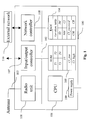
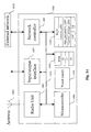
- Figure 1 depicts the electronic circuit of a wireless communication device, using the DECT European standard (specified by the ETSI, ETS 300 175, 1991), which can be connected to a network of the STN (Switched Telecommunication Network), Ethernet etc type.
- DECT European standard specified by the ETSI, ETS 300 175, 1991
- STN Switchched Telecommunication Network
- This device can be either a DECT base station, or a DECT hybrid station.
- a DECT base station is responsible notably for providing the synchronisation of the system.
- a hybrid station is a communication station which can alternately operate as a base station or as a mobile station. This communication device can be integrated into equipment of the computer, printer, fax etc type or be connected to one of the above mentioned items of equipment.
- the electronic circuit 100 includes, connected together by an address and data bus 102:
- an electrical power supply 109 is provided for powering all the components of the electronic circuit 100 (the electrical connections concerning the power supply 109 are not shown).
- the network controller 108 manages the interface with an external network 110, for example of the Switched Telephone Network type.
- the input/output controller is connected to an information source (for example an image, sound, text or graphics sensor, a telephone, a facsimile machine, a photographic apparatus, a video camera, a camcorder etc) and/or to an information destination (for example a television receiver, a monitor, a music system, a telephone, a facsimile machine, a video recorder etc).
- an information source for example an image, sound, text or graphics sensor, a telephone, a facsimile machine, a photographic apparatus, a video camera, a camcorder etc
- an information destination for example a television receiver, a monitor, a music system, a telephone, a facsimile machine, a video recorder etc.
- the central unit 106 is also adapted to implement the method of the invention and, in particular, the flow diagrams illustrated in the figures.
- the random access memory 104 stores, in registers which, for convenience, each bear the same name as the data which they contain:
- the read only memory 105 stores, in registers which, for convenience, each bear the same name as the data which it contains:
- the read only memory 105 constitutes a means of storing information which can be read by a computer or a microprocessor, storing instructions of a computer program characterized in that it makes it possible to implement the method of the invention.
- the read only memory 105 is removable, partially or totally, and has, for example, a magnetic tape, a flash memory, diskette or a fixed-memory compact disc (CD-ROM).
- Figure 2 depicts the electronic circuit of a wireless communication device, using the DECT European standard (specified by the ETSI, ETS 300 175, 1991), functioning in mobile station mode.
- This device can be either a DECT mobile station, or a DECT hybrid station.
- This communication device can be integrated into an item of equipment of the computer, printer, facsimile machine etc type or connected to one of the aforesaid items of equipment.
- the electronic circuit 200 includes, connected together by an address and data bus 202:
- an electrical power supply 209 is provided for supplying all the components of the electronic circuit 200 (the electrical connections concerning the power supply 209 are not shown).
- the input/output controller 207 is connected to an information source (for example an image, sound, text or graphics sensor, a telephone, a facsimile machine, a photographic apparatus, a video camera, a camcorder etc) and/or to an information destination (for example a television receiver, a monitor, a music system, a telephone, a facsimile machine, a video recorder etc).
- an information source for example an image, sound, text or graphics sensor, a telephone, a facsimile machine, a photographic apparatus, a video camera, a camcorder etc
- an information destination for example a television receiver, a monitor, a music system, a telephone, a facsimile machine, a video recorder etc.
- the central unit 206 is also adapted to implement the method of the invention and, in particular, the flow diagrams illustrated in the figures.
- the random access memory 204 stores, in registers which, for convenience, each bear the same name as the data which they contain:
- the read only memory 205 stores, in registers which, for convenience, each bear the same name as the data which it contains:
- the read only memory 205 constitutes a means of storing information which can be read by a computer or a microprocessor, storing instructions of a computer program characterized in that it makes it possible to implement the method of the invention.
- the read only memory 205 is removable, partially or totally, and includes, for example, a magnetic tape, a flash memory, a diskette or a fixed-memory compact disc (CD-ROM).
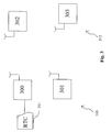
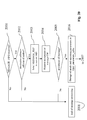
- Figure 3 depicts a local wireless communication network 310 comprising:
- the mobile stations 301, 302 and 303 are synchronised with the base station 300.
- the base station 300 if the mobile stations 302 and 303 wish to communicate together, the base station 300 initiates a suitable procedure so that the stations 302 and 303 communicate directly, without transmitting data through the base station 300. To this end, the base station 300 sends a message to the hybrid station 303, requesting it to switch into base station mode, and a message to the mobile station 302, requesting it to synchronise on the station 303.
- the problem is that the stations 302 and 303 are no longer correctly synchronised with the base station 300. Consequently, whilst the stations 302 and 303 constitute a subcell 312 in the local wireless network, neither the station 301 nor the base station 300 can communicate either with the station 302 or with the station 303.
- the present invention makes it possible to resolve this problem.
- the present invention aims to transmit short messages (that is to say those which can be contained in the memory of a mobile station and, preferentially, whose transmission requires one or two radio frames), making it possible to transfer a command or an item of information from a first communication device to a second communication device, the first device and the second device being situated in radio cells situated in the same local area, but not being synchronised with each other, nor with the same station functioning in base station mode.
- the content of the short message can be either intended for the user of the destination station (equivalent to a short message known as SMS, standing for "Short Message System” in the GSM standard, the acronym for "Global System for Mobile communication”), or intended for the central processing unit 206 of the destination station.
- the short messages thus transmitted have, for example, the following functions:
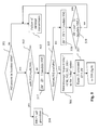
- the base station 300 When the base station 300 wishes to send a short message to the station 302, for example, the base station 300 will execute the algorithm illustrated in Figures 5 and 6 .
- the base station 300 attempts to locate the station 302 by determining whether the identifier of the station 302 is situated in a location table illustrated in Figures 4a and 4b, which it stores in its random access memory 104.
- This table contains:
- Figure 4a which represents the location table corresponding to a single cell
- the three stations 301, 302 and 303 are functioning in mobile station mode, the mode indicated by the letters "PP", the acronym for “portable part”, in the central column and are all synchronised on the station functioning in base station mode 300, indicated in the right-hand column.
- the location table illustrated in Figure 4b corresponds to the creation of the subcell 312:
- the base station 300 updates a location table.
- the initial location table of the system is depicted in Figure 4a. This table indicates that the cell, for which the station 300 is the base station, has three stations in mobile mode: 301, 302 and 303.
- the table depicted in Figure 4b indicates the configuration of the system after a direct communication cell has been formed between the station 302 and the station 303, as described previously. This table indicates that the station 301 is still synchronised with the station 300 and that, on the other hand, the station 303 has switched into base station mode and the station 302 is synchronised with the station 303.
- the result of the test 501 is positive.
- the result of the test 501 is negative, during an operation 502, a failure message is transmitted to the source of the message to be transmitted or to the user of the station 300 and the implementation of the algorithm is terminated until a new message is to be transmitted by the station 300.
- the central unit 106 determines whether the station 302 is in the same cell as the station 300, that is to say whether they are both synchronised with the same base station or whether one of them is functioning in base station mode and the other is synchronised on it.
- the central unit 106 determines whether or not the indicator indicated in the right-hand column of the location table, in the row corresponding to station 302, is the identifier of the station 300.
- the station 300 transmits the message which it has to deliver to the station 302 in accordance with the procedures known in the implementation of the DECT standard.
- the system includes several mobile stations, it will not always be the same mobile station which will be requested to become a relay station.
- Step 517 is followed by step 505, during which the central unit 106 determines whether the mobile station corresponding to the index IM is available for becoming a relay station. It should be stated here that a station is considered to be available if it is operating in mobile station mode (and not in base station mode) and if it is not currently communicating (sending or receiving) a message.
- the operation 518 is performed. During the operation 518, the index IM is incremented by 1 modulo MN. Next, during a test 519, the central unit 106 determines whether or not the value of IM is equal to that of ID + 1, modulo NM. If the result of test 519 is positive, the operation 502 is performed.
- the rotating selection of a relay mobile station (operation 517, 505, 518, 519), can be replaced by a pseudo-random selection.
- the central unit 106 sends to the available mobile station, here the station 301, a message "request_relay" of the form ⁇ CM , 302, 303, 300 >, in which the first term, CM , represents the content of the message to be transmitted, the second term, here 302, indicates the final destination of the message, the third term, here 303, indicates the station functioning in base station mode with which the station 301 will have to synchronise for the transmission of the message, and the fourth term, here 300, indicates the message source station.
- CM represents the content of the message to be transmitted
- the second term, here 302 indicates the final destination of the message
- the third term, here 303 indicates the station functioning in base station mode with which the station 301 will have to synchronise for the transmission of the message
- the fourth term, here 300 indicates the message source station.
- a clock pulse downcounter is initialised and started.
- a pulse downcounter is known as a timer.
- the period T1 during which its value is positive is known in advance.
- the variable ID is then updated with the value of IM, so that, when a future relay message is transmitted, the selection of the new relay station does not commence with the station corresponding to the index ID.
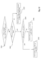
- the central unit 106 determines whether or not a message "relay_accepted" has been received from the station 301. When the result of the test 508 is negative, during a test 509, the central unit 106 determines whether or not a message "relay_rejected" has been received by the station 301. When the result of the test 509 is negative, during a test 510, the central unit 106 determines whether the period T1 has elapsed, by determining whether or not the value of the timer of period T1 is nil.
- test 508 is reiterated.
- the central unit 106 determines whether or not a mobile station other than the station 301 (and more generally, whether or not all the mobile stations already considered to be available during the message transmission attempt under consideration) is available in the cell.
- operation 502 is performed.
- operation 506 is reiterated, taking account of the new mobile station considered to be available.
- test 511 is performed.
- a timer of duration T2 is initialised and started.
- the central unit 106 determines whether or not a message "relay_message_response" has been received from the station 302.
- the central unit 106 determines whether or not the value of the timer of duration T2 is nil.
- test 513 is reiterated.
- the result of test 514 is positive, during an operation 515, the absence of a response is processed.
- test 511 is performed.
- the result of test 513 is positive, during an operation 516, the response received from the station 302 is processed and, in the event of failure of the processing (for example if the message "relay_message_response" contains information representing failure, see operation 711, Figure 7), the test 511 is performed.
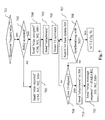
- Figure 7 illustrates the algorithm implemented by the station 301, during the functioning of the station 300 illustrated in Figures 5 and 6, when the station 301 is the station considered as being available during the operation 505.
- the central unit 206 of the station 301 determines, during a test 701, whether or not a message "request_relay" for the station 301 has been received. When the result of test 701 is positive, during a test 702, the central unit 206 of the mobile station 301 determines whether or not the relay role is accepted.
- the central unit 206 determines whether a communication would be interfered with by the detachment and attachment operation and, if during the availability test 702 it is determined that no communication would be interfered with by a detachment and attachment operation, the result of test 702 is positive.
- the central unit 206 determines whether or not the station 301 is participating in a current communication and, if it is participating in a current communication, it is determined that a communication would be interfered with by a detachment and attachment operation and the result of test 702 is negative.
- the central unit 206 determines whether or not a quantity of energy available to the station 301 is greater than a predetermined quantity and, if during test 702 it is determined that the quantity of energy is greater than said predetermined quantity, the result of test 702 is positive.
- the central unit 206 can, where the power supply to the mobile station comes from an accumulator or battery, determine whether the current value of the available energy level ( NE ) is greater than a predefined value ( NE_MIN ), in order to accept or not the role of relay.
- the central unit 206 determines that the station 301 will have no message to send or receive during a predetermined period T2 to come, it considers that the role of relay must be accepted (result of test 702 positive) and that otherwise it must be refused.
- the central unit 206 causes to be sent to the station 301 a message "relay_rejected" of the form ⁇ CM, 303, 302, 300> in which the first term, CM , represents the content of the message, the second term, 303, represents the base station with which the station 301 was to synchronise, the third term, 302, represents the message destination station and the fourth term, 300, represents the station at the source of the message.
- the central unit 206 causes to be sent to the station 301 a message "relay_accepted" of the form ⁇ CM, 303, 302, 300> in which the first term, CM, represents the content of the message, the second term, 303, represents the base station with which the station 301 is to synchronise, the third term, 302, represents the message destination station and the fourth term, 300, represents the source of the message.
- the central unit 206 causes the detachment of the station 301 from the base station 300, in accordance with known procedures, including notably the sending of a detachment message to the base station 300.
- the central unit 206 initialises a timer of predetermined duration T3 and starts it.
- the central unit 206 seeks the base station 303 in order to synchronise with it.
- the central unit 206 determines whether or not the base station 301 has succeeded in synchronising with the base station 303.
- the central unit 206 determines whether or not the value of the timer of predetermined period T3 is nil.
- operation 707 is reiterated.
- the central unit 206 which has remained synchronised with the base station 300, sends it an attachment message during an operation 710.
- the mobile station 301 cannot synchronise with the station 303 may be that the stations 301 and 303 are situated at two ends of the local area and that the synchronisation signal sent by the base station 303 is too weak or too noisy to be correctly received and used by the mobile station 301.
- the central unit 206 causes the sending by the station 301 of a message "relay_message_response" of the form ⁇ FAILURE, 303, 302, 300> in which the first term “FAILURE” indicates that the message to be relayed has not been able to be transferred, the second term, 303, represents the base station with which the station 301 was to synchronise, the third term 302, represents the message destination station and the fourth term, 300, represents the station at the source of the message.
- the central unit 206 causes the sending of attachment message to the base station 303. Then, during an operation 713, the central unit 206 causes the sending, to the station 302, of a message "relay_message" of the form ⁇ CM, 300> in which the first term, CM, represents the content of the message and the second term, 300, represents the source of the message.
- the central unit 206 initialises a timer of predetermined duration T4 and starts it.
- the central unit 206 determines whether or not a message "relay_message_response" has been received from the mobile station 302.
- the central unit 206 determines whether or not the value of the timer of duration T4 is nil.
- the test 715 is reiterated.
- a message “response_relay” is formed in the form ⁇ NONE, 300, 302> in which the first term indicates that no response has been received from the station 302, the second term indicates the destination station for the message “response_relay” and the third term indicates the station from which a message “relay_message_response” was awaited.
- a message “response_relay” is formed in the form ⁇ CR , 300, 302> in which the first term contains the content of the response, a content drawn from the message "relay_message_response” transmitted by the station 302, the second term indicates the destination station for the message “response_relay” and the third term indicates the station from which a message “relay_message_response” was awaited.
- the central unit 206 causes the sending, to the base station 303, of a detachment message. Then, during an operation 720, the central unit 206 initialises a timer of predetermined duration T5 and starts it. Then, during an operation 721, the central unit 206 seeks the base station 300, the station which is the source of the message "request_relay" .
- the central unit 206 determines whether or not the station 301 has succeeded in synchronising with the base station 300.
- the central unit 206 determines whether or not the value of the timer of duration T5 is nil.
- operation 721 is reiterated.
- the central unit 206 which has remained synchronised with the base station 303, sends an attachment message to it, during an operation 724.
- the central unit 206 causes an attachment message to be sent by the mobile station 301 to the base station 300. Then, during an operation 726, the central unit 206 causes the message "response_relay" to be sent by the mobile station 301 to the station which is the destination of the message "response_relay" (station 300).
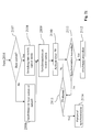
- Figure 10 illustrates an algorithm followed by the central unit 206 of the station 302 which is the destination of a message coming from the station 300, by means of the station 301 which served as a relay between two adjacent cells.
- the central unit 206 determines whether or not a message "relaymessage" has been received. When the result of test 801 is positive, during an operation 802, the central unit 206 performs a processing of the content of the message received. Then, during an operation 803, the central unit 206 effects a sending of a message "relay_message_response" of the form ⁇ CR , 300, 302> in which the first term contains the content of the response intended for the station 300, indicated by the second term, the third term indicating the station which is the source of this message.
- the content of this message may mean that the station 302 will detach itself from the station 303 and synchronise with the station 300 with a view to receiving a message.
- the lapse of time is depicted from top to bottom, each period of a timer being depicted by a segment of a vertical straight line.
- a message "request_relay" 901 is sent by the station 300 to the station 301 (operations 506, Figure 5 and 701, Figure 7).
- a detachment message 903 is sent by the station 301 to the base station with which it was, until then, synchronised (operation 705).
- the station 301 seeks the synchronisation signal sent by the base station 303 (operation 707, Figure 7 and 904, Figure 11).
- the station 301 sends, to the station 303, an attachment message 905 (operation 712, Figure 8).
- the station 301 sends, by means of the station 303, to the station 302, a message "relay_message" 906 (operations 713, Figure 8, and 801, Figure 10).
- the station 302 sends, by means of the station 303, to the station 301, a message "relay_message_response" 907 (operations 715, Figure 8 and 803, Figure 10).
- the station 301 sends a detachment message 908 to the base station 303 (operation 719, Figure 9).
- the station 301 seeks the synchronisation signal sent by the base station 300 (operation 721, Figure 9, and 909, Figure 11).
- the station 301 sends an attachment message 910 to the station 300 (operation 725, Figure 9).
- the station 301 sends a message "relay_message_response" 911 to the station 300 (operations 513, Figure 6, and 726, Figure 9).
- An example of an application of this invention concerns the distribution of the data stream between two adjacent cells.
- a short message of the type CM LOAD_INFO ⁇ Identity FP, cell loads ⁇ " can be exchanged between the two base stations of two adjacent cells, the first term representing the identity of the base station of a cell, and the second term representing the load on the cell (the ratio between the passband used and the available passband).
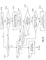
- Figure 12 depicts the algorithm executed by the base station 303 when it receives a message of the type "LOAD_INFO", test 1001 positive.
- Such a message can be sent by a base station to an adjacent cell when the value of its load Cl, permanently stored in random access memory 104, is less than the value Cl_LOW stored in read only memory 105.
- the station 303 On receipt of this message, the station 303 prepares and sends a response to this message, which contains the control field "LOAD_INFO" as well as the value Cl read in the random access memory 204, representing the load on the cell for which the station 303 is the base station, during an operation 1002.
- the content of the response that is to say the content of the field CR, is transmitted as indicated at step 803.
- the station 303 analyses whether or not its passband is excessively used, during a test 1003, by determining whether or not the value of Cl read in the random access memory 204 is greater than the value Cl_HIGH stored in read only memory 205.
- the central unit 206 determines whether or not the passband available in the cell for which the station 300 is the base station is too little used. If the result of the test 1004 is negative then no specific processing is to be carried out and the implementation of the algorithm illustrated in Figure 12 ends. On the other hand, if the result of the test 1004 is positive, the base station 303 attempts to redirect a communication established in its cell to the base station 300 so that all the stations to which said communication relates synchronise on the base station 300 with a view to balancing the available passband between the two cells.
- the base station 303 In order to reroute a communication from the cell of the base station 303 to the base station 300, during an operation 1005, the base station 303 sends, to the mobile stations involved in the communication to be rerouted, a message indicating to them that they should synchronise with the station 300.
- the central unit 206 determines whether or not the sum of Cl_received and the value of Cl stored in the random access memory 204 is less than the value Cl_LOW stored in the read only memory 205.
- the station 303 switches into mobile station mode, during an operation 1007. In this way, the two cells merge, that is to say all the mobile stations in the cell for which the base station was the station 303 and this station 303 synchronise with the base station 300.
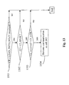
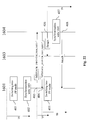
- Figure 13 depicts the algorithm executed by the base station 300, when it receives a response to a short message of the type "LOAD_INFO". The reception of this response is determined by a test for the reception of such a message 1101.
- the central unit 106 of the station 300 determines whether or not the passband of the cell of the base station 300 is excessively used, determining whether or not the value of the variable C/ stored in the random access memory 104 is greater than the value of Cl_HIGH stored in the read only memory 105.
- the central unit 106 determines whether or not the value of the passband of the cell for which the base station is the station 303, a value which is transmitted in the response message, is less than the value Cl_LOW stored in the read only memory 105.
- the base station 300 attempts to redirect a communication established in its cell to the base station 303 so that all the stations to which said communication relates synchronise on the base station 303 with a view to balancing the passband available between the two cells.
- the base station 300 In order to reroute a communication from the cell of the base station 300 to the base station 303, the base station 300 sends, to the mobile stations involved in the communication to be rerouted, a message indicating to them that they should synchronise with the station 303.
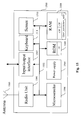
- Figure 14 depicts the electronic circuit of a wireless communication device, using the DECT European standard (specified by the ETSI, ETS 300 175, 1991), which can be connected to a network of the STN (Switched Telecommunication Network), Ethernet etc type.
- DECT European standard specified by the ETSI, ETS 300 175, 1991
- STN Switchched Telecommunication Network
- This device can be either a DECT base station, or a DECT hybrid station.
- a DECT base station is responsible notably for providing the synchronisation of the system.
- a hybrid station is a communication station which can alternately operate as a base station or as a mobile station. This communication device can be integrated into equipment of the computer, printer, fax etc type or be connected to one of the aforementioned items of equipment.
- the electronic circuit 1400 includes, connected together by an address and data bus 1402:
- an electrical power supply 1409 is provided for powering all the components of the electronic circuit 1400 (the electrical connections concerning the power supply 1409 are not shown).
- the network controller 1408 manages the interface with an external network 1410, for example of the Switched Telephone Network type.
- the input/output controller 1407 is connected to an information source (for example an image, sound, text or graphics sensor, a telephone, a facsimile machine, a photographic apparatus, a video camera, a camcorder etc) and/or to an information destination (for example a television receiver, a monitor, a music system, a telephone, a facsimile machine, a video recorder etc).
- an information source for example an image, sound, text or graphics sensor, a telephone, a facsimile machine, a photographic apparatus, a video camera, a camcorder etc
- an information destination for example a television receiver, a monitor, a music system, a telephone, a facsimile machine, a video recorder etc.
- the central unit 1406 is also adapted to implement the method of the invention and, in particular, the flow diagrams illustrated in figures 18 and 19.
- the random access memory 1404 stores, in registers which, for convenience, each bear the same name as the data which they contain:
- the read only memory 1405 stores, in registers which, for convenience, each bear the same name as the data which they contain:
- the read only memory 1405 constitutes a means of storing information which can be read by a computer or a microprocessor, storing instructions of a computer program characterized in that it makes it possible to implement the method of the invention.
- the read only memory 1405 is removable, partially or totally, and has, for example, a magnetic tape, a flash memory, a diskette or a fixed-memory compact disc (CD-ROM).
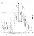
- Figure 15 depicts the electronic circuit of a wireless communication device, using the DECT European standard (specified by the ETSI, ETS 300 175, 1991), functioning in mobile station mode.
- This device can be either a DECT mobile station, or a DECT hybrid station.
- This communication device can be integrated into an item of equipment of the computer, printer, facsimile machine etc type or connected to one of the aforesaid items of equipment.
- the electronic circuit 1500 includes, connected together by an address and data bus 1502:
- an electrical power supply 1509 is provided for supplying all the components of the electronic circuit 1500 (the electrical connections concerning the power supply 1509 are not shown).
- the input/output controller 1507 is connected to an information source (for example an image, sound, text or graphics sensor, a telephone, a facsimile machine, a photographic apparatus, a video camera, a camcorder etc) and/or to an information destination (for example a television receiver, a monitor, a music system, a telephone, a facsimile machine, a video recorder etc).
- an information source for example an image, sound, text or graphics sensor, a telephone, a facsimile machine, a photographic apparatus, a video camera, a camcorder etc
- an information destination for example a television receiver, a monitor, a music system, a telephone, a facsimile machine, a video recorder etc.
- the central unit 1506 is also adapted to implement the method of the invention and, in particular, the flow diagrams illustrated in Figures 20 and 21.
- the random access memory 1504 stores, in registers which, for convenience, each bear the same name as the data which they contain:
- the read only memory 1505 stores, in registers which, for convenience, each bear the same name as the data which they contain:
- the read only memory 1505 constitutes a means of storing information which can be read by a computer or a microprocessor, storing instructions of a computer program characterized in that it makes it possible to implement the method of the invention.
- the read only memory 1505 is removable, partially or totally, and includes, for example, a magnetic tape, a flash memory, a diskette or a fixed-memory compact disc (CD-ROM).
- Figure 16 depicts a local wireless communication network 1610 comprising:
- the base station 1601 if the mobile stations 1603 and 1604 wish to communicate together, the base station 1601 initiates a suitable procedure so that the stations 1603 and 1604 communicate directly, without transmitting data through the base station 1601. To this end, the base station 1601 sends a message to the hybrid station 1603, requesting it to switch into base station mode, and a message to the mobile station 1604, requesting it to synchronise on the base station 1603.
- the problem is that the stations 1603 and 1604 are no longer correctly synchronised with the base station 1601. Consequently, whilst the stations 1603 and 1604 constitute a subcell 1606 in the local wireless network, the station 1601 cannot communicate either with the station 1604 or with the station 1603.
- the present invention allows to resolve this problem.
- the present invention aims to transmit short messages (that is to say those which can be contained in the memory of a mobile station and, preferentially, whose transmission requires one or two radio frames), making it possible to transfer a command or an item of information from a first communication device to a second communication device, the first device and the second device being situated in radio cells situated in the same local area, but not being synchronised with each other, nor with the same station functioning in base station mode.
- the content of the short message can be either intended for the user of the destination station (equivalent to a short message known as SMS, standing for "short message system" in the GSM standard, the acronym for "Global System for Mobile communication", or intended for the central processing unit 1506 of the destination station.
- the short messages thus transmitted have, for example, the following functions:
- the base station 1601 receives a message coming from the external network 1602 and intended for a so-called "destination" station 1604. Then, during an operation 1802, the base station 1601 seeks the location of the destination station 1604 by reading a location table stored in the random access memory 1404 (see Figures 17a and 17b).
- This table contains:
- FIG 17a which depicts the location table corresponding to a single cell
- the two stations 1604 and 1603 are functioning in mobile station mode, the mode indicated by the letters "PP”, the acronym of the words “portable part”, in the central column and are all synchronised on the station functioning in base station mode 1601, indicated in the right-hand column.
- the location table illustrated in Figure 17b corresponds to the creation of the subcell 1606:
- the base station 1601 updates its location table.
- the central unit 1406 determines whether or not the station 1604 is in the location table. When the result of test 1803 is negative, during an operation 1805, the call coming from the external network 1602 is rejected. When the result of test 1803 is positive, during a test 1804, the central unit 1406 determines whether or not the station 1604 is situated in the cell 1605, by determining whether or not, in the location table, in the row of the station 1604, the identifier of the base station 1601 is situated in the right-hand column.
- the message intended for the station 1604 is transmitted to it within the cell 1605, according to known procedures in accordance with the DECT standard.
- the central unit 1406 determines whether or not there is a communication under way in the cell 1605.
- the call rejection operation 1805 is performed.
- the central unit 1406 seeks, in the cell 1605, a station capable of functioning in base station mode and of ensuring the communications under way, and sends to it a request to change to base station mode.
- the station 1601 starts to function in mobile station mode if another station takes the role of base station, and then performs the operation 1808 (below).
- the processing unit 1406 updates the variables "Base_parameters_table” and " External_message_table " stored in the random access memory 1404.
- the variable “Base_parameters_table” contains all the information representing the state of the station 1601 before it switches to mobile station mode.
- “Base_parameters_table” stores all the databases related to the subscription parameters of the mobile stations which are registered with the base station 1601.
- the variable " External_message_table " contains all the information necessary to the station 1601 for it to be able to manage this call when it returns to base station mode.
- this table will make it possible to store whether there is a call waiting, the number of the person called and of the caller, etc.
- the station 1601 switches into mobile station operation mode.
- a clock pulse downcounter is initialised to a positive integer value and activated.
- a pulse downcounter is known as a "timer”. Its value decreases by one, with each pulse of a clock or clock divider.
- the time T6 during which its value is positive is known in advance. When its value reaches "0", its operation is automatically stopped.
- the central unit 1406 determines whether or not the station 1601 has synchronised with the base station 1603. When the result of the test 1911 is negative, during a test 1912, the central unit 1406 determines whether or not the value of the timer of duration T6 is nil.
- test 1911 is reiterated.
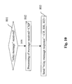
- station 1601 switches into base station mode and then, during an operation 1918, restores its base station mode operating parameters, as they were before the operation 1808, and sends, to the external network station which is at the origin of the call of the station 1604, a message representing failure to make immediate communication with the station 1604.
- the operation 1805 is performed.
- a message " MESSAGE_INFO " is transmitted to the mobile station 1604, with the field CM representing an external call, in accordance with the procedures known in the DECT standard.
- a timer of duration T7 is initialised and started.
- the central unit 1406 determines whether or not a message "MESSAGE_REP" has been received coming from the mobile station 1604, with a field CR representing an acceptance of a call.
- the central unit 1406 determines whether or not the value of the timer of duration T7 is nil.
- the test 1915 is reiterated.
- the operation 1917 is performed.
- the central unit 1406 determines whether or not the content of the response message represents an acceptance.
- the operation 1917 is performed.
- a timer of predetermined duration T8 is initialised and activated.
- the station 1601 returns to base station operating mode with the operating parameters stored in the random access memory 1404.
- the interlocutor at the origin of the message intended for the station 1604, on the network 1602 receives, from the station 1601, a message representing failure of the procedure to get into immediate communication with the station 1604.
- the timer is not activated during the operation 1919 since no response is awaited by the correspondent calling by means of the external network. This case applies in particular to notifications of reception of electronic messages (email) or faxes.
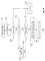
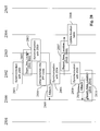
- Figures 20 and 21 represent an algorithm executed by the station 1604 on reception of a message coming from the station 1601 using the algorithm illustrated in Figures 18 and 19. It should be noted here that the station 1603 uses the same algorithm when it is the called station.
- the central unit 1506 of the station 1604 determines whether or not a message of the "MESSAGE_INFO" type has been received. When the result of the test 2000 is negative, the processing of the message received is in accordance with the specifications of the DECT standard, during an operation 2001.
- the central unit 1506 determines whether or not the destination address of the message "MESSAGE_INFO" is the address of the station 1604. When the result of the test 2002 is negative, the operation 2001 is performed. When the result of the test 2002 is positive, during an operation 2003, the central unit 1506 sends a message "MESSAGE_REP", with the field CR representing an acceptance, to the station 1601. This acceptance means simply that the station 1604 has correctly received the message coming from the station 1601. The acceptance message is returned before the processing of the content of the message received, in order to enable the station 1601, as soon as possible, to return to base station mode.
- the central unit 1506 reads the message acceptance request including a content CM, a request which is contained in the message "MESSAGE_INFO".
- the message coming from the external network is a message whose content cannot be inserted in the message "MESSAGE_INFO", because of its size, and whose communication requires a passband such that it is necessary for a new cell to be created with solely the stations 1601 (operating in base station mode) and 1604 (operating in mobile station mode).
- the terminal receiving the message signifies solely the correct reception of the message and is therefore not obliged to implement the succession of steps described in Figures 20 and 21.
- the central unit 1506 determines whether or not the content message CM is accepted as an urgent message.
- the operation 2001 is performed.
- the operating mode of the station 1604 is stored in random access memory 1504 and, in particular, the operating mode, base station or mobile station and, optionally, the identifier of the base station with which the station 1604 is synchronised.
- the central unit 1506 determines whether or not the operating mode is that of base station. When the result is positive, during an operation 2108:
- the central unit 1506 causes to be sent, by the station 1604, a detachment message to the base station of the cell 1606, indicating to it that it is leaving the cell.
- the central unit 1506 attempts to synchronise with the station which sent the message "MESSAGE_INFO" (the latter then functioning in base station mode).
- the central unit 1506 initialises a timer of predetermined duration T9 and activates it. Then, during a test 2111, the central unit 1506 determines whether or not the synchronisation with the station 1601 has been effected. When the result of the test 2111 is negative, during a test 2113, the central unit 1506 determines whether or not the value of the timer of duration T9 is nil. When the result of the test 2113 is negative, the test 2111 is reiterated. When the result of the test 2113 is positive, during an operation 2114, a synchronisation failure procedure is effected and the initial operating state of the station 1604, with its operating parameters stored in the random access memory 1504, is restored. In the event of failure of synchronisation with the base station with which the station 1604 was, if applicable, initially synchronised, or in the event of the presence of a new base station, the station 1604 synchronises with any base station present.
- the central unit 1506 causes the attachment of the station 1604 with the station 1601. Next, the cell which includes solely the stations 1601 and 1604 is created and communication is established.
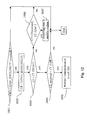
- each duration of a timer being depicted by a segment of a vertical straight line.
- the station 1601 performs an operation of synchronisation with the station 1603, during an operation 402 (operation 1911, Figure 19). Then the station 1601 sends, by means of the base station 1603, a message "MESSAGE_INFO ⁇ CM, 1604,1601>", in which the first term includes the content of the message, the second identifier of the message destination station and the third identifier of the message source station, during an operation 403 (operations 1913, Figure 19, and 2000, Figure 20).
- the mobile station 1604 returns to the station 1601, by means of the base station 1603, a message "MESSAGE_REP ⁇ CR,1601,1604>, in which the first term represents the content of the response, the second the station which is the destination of the response and the third the station which was the source of the response, during an operation 404 (operations 2003, Figure 20, and 1915, Figure 19).
- the station 1604 sends a detachment message 406 (operation 2106, Figure 21) to the base station 1603, and the station 1601 switches into base station mode (operation 1919, Figure 19).
- the mobile station 1604 synchronises with the base station 1601 during an operation 407 (operations 2109 to 2111 and 2113, Figure 21). Finally, the mobile station 1604 sends a signal of attachment to the base station 1601, during an operation 408 (operation 2112, Figure 21).
- the mobile station 1604 communicates at a distance, over the external network, by means of the base station 1601.
- the synchronisation operation includes an operation of switching the destination station into mobile mode and an operation of attachment with the source station 1601.
- Figure 23 depicts the electronic circuit of a wireless communication device, using the DECT European standard (specified by the ETSI, ETS 300 175, 1991), which can be connected to a network of the STN (Switched Telecommunication Network), Ethernet etc type.
- DECT European standard specified by the ETSI, ETS 300 175, 1991
- STN Switchched Telecommunication Network
- This device can be either a DECT base station, or a DECT hybrid station.
- a DECT base station is responsible notably for providing the synchronisation of the system.
- a hybrid station is a communication station which can alternately operate as a base station or as a mobile station. This communication device can be integrated into equipment of the computer, printer, fax etc type or be connected to one of the above mentioned items of equipment.
- the electronic circuit 2300 includes, connected together by an address and data bus 2302:
- an electrical power supply 2309 is provided for powering all the components of the electronic circuit 2300 (the electrical connections concerning the power supply 2309 are not shown).
- the network controller 2308 manages the interface with an external network 2310, for example of the switched telephone network type.
- the input/output controller is connected to an information source (for example an image, sound, text or graphics sensor, a telephone, a facsimile machine, a photographic apparatus, a video camera, a camcorder etc) and/or to an information destination (for example a television receiver, a monitor, a music system, a telephone, a facsimile machine, a video recorder etc).
- an information source for example an image, sound, text or graphics sensor, a telephone, a facsimile machine, a photographic apparatus, a video camera, a camcorder etc
- an information destination for example a television receiver, a monitor, a music system, a telephone, a facsimile machine, a video recorder etc.
- the central unit 2306 is also adapted to implement the method of the invention and, in particular, the flow diagram illustrated in Figure 32.
- the random access memory 2304 stores, in registers which, for convenience, each bear the same name as the data which they contain:
- the read only memory 2305 stores, in registers which, for convenience, each bear the same name as the data which they contain:
- the read only memory 2305 constitutes a means of storing information which can be read by a computer or a microprocessor, storing instructions of a computer program characterized in that it makes it possible to implement the method of the invention.
- the read only memory 2305 is removable, partially or totally, and has, for example, a magnetic tape, a flash memory, a diskette or a fixed-memory compact disc (CD-ROM).
- Figure 24 depicts the electronic circuit of a wireless communication device, using the DECT European standard (specified by the ETSI, ETS 300 175, 1991), functioning in mobile station mode.
- This device can be either a DECT mobile station, or a DECT hybrid station.
- This communication device can be integrated into an item of equipment of the computer, printer, facsimile machine etc type or connected to one of the aforesaid items of equipment.
- the electronic circuit 2400 includes, connected together by an address and data bus 2402:
- an electrical power supply 2409 is provided for supplying all the components of the electronic circuit 2400 (the electrical connections concerning the power supply 2409 are not shown).
- the input/output controller 2407 is connected to an information source (for example an image, sound, text or graphics sensor, a telephone, a facsimile machine, a photographic apparatus, a video camera, a camcorder etc) and/or to an information destination (for example a television receiver, a monitor, a music system, a telephone, a facsimile machine, a video recorder etc).
- an information source for example an image, sound, text or graphics sensor, a telephone, a facsimile machine, a photographic apparatus, a video camera, a camcorder etc
- an information destination for example a television receiver, a monitor, a music system, a telephone, a facsimile machine, a video recorder etc.
- the central unit 2406 is also adapted to implement the method of the invention and, in particular, the flow diagrams illustrated in Figures 29, 30 and 31.
- the random access memory 2404 stores, in registers which, for convenience, each bear the same name as the data which they contain:
- the read only memory 2405 stores, in registers which, for convenience, each bear the same name as the data which they contain:
- the read only memory 2405 constitutes a means of storing information which can be read by a computer or a microprocessor, storing instructions of a computer program characterized in that it makes it possible to implement the method of the invention.
- the read only memory 2405 is removable, partially or totally, and includes, for example, a magnetic tape, a flash memory, a diskette or a fixed-memory compact disc (CD-ROM).
- Figure 25 depicts a local wireless communication network 2510 comprising:
- the mobile station 2501 is synchronised with the base station 2500 and the mobile stations 2503, 2504 and 2505 are synchronised with the base station 2502.
- the base station 2502 if the mobile stations 2504 and 2505 wish to communicate together, the base station 2502 initiates a suitable procedure so that the stations 2504 and 2505 communicate directly, without transmitting data through the base station 2502. To this end, the base station 2502 sends a message to the hybrid station 2504, requesting it to switch into base station mode, and a message to the mobile station 2505 requesting it to synchronise on the station 2504.
- the location table of the base station 2500 contains the following information: Identifier Operating mode Last attachment station 2500 Base 2500 2501 Mobile 2500 2502 Base 2500 2503 Mobile 2502 2504 Mobile 2502 2505 Mobile 2502
- the location table of the base station 2502, in the configuration illustrated in Figure 25, contains the following information: Identifier Operating mode Last attachment station 2500 Base unknown 2501 Mobile unknown 2502 Base 2500 2503 Mobile 2502 2504 Mobile 2502 2505 Mobile 2502
- the location table of the base station 2500 contains the following information: Identifier Operating mode Last attachment station 2500 Base 2500 2501 Mobile 2500 2502 Base 2500 2503 Mobile 2502 2504 Mobile 2502 2505 Mobile 2502
- the location table of the base station 2502, in the configuration illustrated in Figure 26, contains the following information: Identifier Operating mode Last attachment station 2500 Base unknown 2501 Mobile unknown 2502 Base 2500 2503 Mobile 2502 2504 Base 2502 2505 Mobile 2504
- the location table of the base station 2504, in the configuration illustrated in Figure 26, contains the following information: Identifier Operating mode Last attachment station 2500 Base unknown 2501 Mobile unknown 2502 Base unknown 2503 Mobile unknown 2504 Base 2502 2505 Mobile 2504
- the base station 2500 wishes to send a message to a mobile station 2505, it should send it to the cell consisting of the stations 2504 and 2505 and not, as indicated in its location table, to the cell containing the base station 2502.
- This error may be the source of delay in transmission and, when the response times are fixed by timers, may result in failures to connect.
- the information for the latter station may reach it too late for the communication to be able to be established.
- the present invention sets out to remedy these drawbacks.
- the base station 2500 sends to the mobile station 2501 a message "relay_request" 2700, which represents a request for the transmission, by the station 2501, of a message intended for the station 2505, in the cell where the station 2505 is situated, according to the location table stored by the base station 2500.
- the message "relay_request” represents information according to which a communication coming from the STN network 2511 is intended for the mobile station 2505.
- the cell in question is the one where the base station is the station 2502.
- the mobile station 2501 sends, to the base station 2500, a message "accept_relay" 2701 accepting or refusing transmission of a message to the station 2505.
- this message 2701 is an acceptance message.
- the mobile station 2501 sends, to the base station 2500, a detachment message "detach" 2702 to indicate to the base station 2500 that the mobile station 2501 is desynchronising from the base station 2500 and that it is therefore no longer able to communicate with the base station 2500 nor with the mobile stations which are synchronised with the base station 2500.
- the station 2501 performs an operation 2703 of seeking the base station 2502, that is to say seeking a synchronisation signal transmitted by the base station 2502.
- the mobile station 2501 sends, to the base station 2502, an attachment signal 2704 "attach" in order to indicate to it that it is synchronising with the base station 2502 and that it is able to communicate with the base station 2502 and/or with any mobile stations which are also synchronised with the base station 2502.
- the mobile station 2501 sends, to the mobile station 2505, a signal 2705 "relay_message” in order to transmit to it the message transmitted to it by the base station 2500.
- the base station 2502 which is to transmit this message to the mobile station 2505, compares the identifier of the destination of this message, here 2505, with its location table and determines that the mobile station 2505 is not synchronised with the base station 2502.
- the base station 2502 then transmits, to the mobile station 2501, a message 2706 " report_new_location ⁇ 2505 , 2504 ⁇ " in which the first identifier, here 2505, represents the mobile station sought and the second identifier, here 2504, represents the base station with which the mobile station sought is synchronised.
- the mobile station 2501 then transmits, to the station 2502, a detachment message "detach" 2707 in order to indicate to the base station 2502 that the mobile station 2501 is desynchronising from the base station 2502 and that it is therefore no longer able to communicate with the base station 2502 nor with the mobile stations which are synchronised with the base station 2502.
- the station 2501 performs an operation 2708 of seeking the base station 2504, that is to say seeking a synchronisation signal transmitted by the base station 2504.
- the mobile station 2501 sends, to the base station 2504, an attachment signal 2709 "attach" in order to indicate to it that it is synchronising with the base station 2504 and that it is able to communicate with the base station 2504 and/or with any mobile stations which are also synchronised with the base station 2504.
- the mobile station 2501 sends, to the mobile station 2505, a signal 2710 "relay_message" in order to transmit to it the message transmitted to it by the base station 2500.
- the mobile station 2505 transmits, to the mobile station 2501, a signal 2711 "relay_message_response" which responds to the message 2710.
- this message 2711 represents an acceptance of establishment of communication with the STN network 2511, by means of the base station 2500.
- each of the mobile stations 2501 and 2505 sends a detachment message "detach", 2712 and 2713 respectively, to the base station 2504.
- the mobile stations 2501 and 2505 perform operations 2714 and 2715, respectively, of seeking the base station 2500, that is to say seeking a synchronisation signal transmitted by the base station 2500.
- each of the mobile stations 2501 and 2505 transmits an attachment message "attach", 2716 and 2717 respectively, to the base station 2500.
- the mobile station 2505 next enters into communication with the STN network 2511, by means of the base station 2500.
- Figure 28 depicts the events which follow on from the transmission, by the base station 2500, to the base station 2502, of a message informing the base station 2502 that a communication coming from the STN network 2511 is intended for the base station 2502.
- the base station 2502 decides to get into communication with the STN network 2511, operation 2801. Then the base station 2502 sends, to the mobile station 2503, a message 2802 " report_new_location ⁇ 2502, 2500 ⁇ " in which the first identifier, here 2502, represents the station which is sending the message and the second identifier 2500 represents the base station with which the base station 2502 will synchronise.
- the mobile station 2503 On reception of this message 2802, the mobile station 2503 performs an operation 2803 of seeking the base station 2500, that is to say seeking a synchronisation signal sent by the base station 2500.
- the base station 2502 then switches into mobile station operating mode, during an operation 2804, and the mobile station 2503 sends, to the base station 2500, an attachment signal "attach" 2805.
- the mobile station 2502 determines whether the stations which are represented therein have the following two characteristics:
- the mobile station 2502 For each of the stations which meet these two characteristics (here only the base station 2504 is situated in this case), the mobile station 2502 performs an operation 2806 of seeking the base station 2504, that is to say seeking a synchronisation signal transmitted by the base station 2504.
- the mobile station 2502 sends, to the base station 2504, an attachment signal "attach”, not shown, then a message 2807 " report_new_location ⁇ 2502,2500 ⁇ " in which the first identifier represents the station which is sending the message and the second identifier represents the base station with which the station in question (the station 2502) will synchronise.
- the base station 2504 then performs an operation 2808 of updating its location table, replacing this information, for all the stations which have the station 2502 as the last base station with which they were synchronised, with the base station to which the station in question (here the station 2502) will synchronise (here the base station 2500).
- the mobile station 2502 performs an operation 2809 of seeking the base station 2500, that is to say seeking a synchronisation signal transmitted by the base station 2500.
- the mobile station 2502 sends, to the base station 2500, an attachment signal "attach” 2810.
- the mobile station 2502 sends, to the base station 2500, a message 2811 " report_new_location ⁇ 2505,2504 ⁇ " in which:
- the base station 2500 updates its location table, taking into account the attachments represented by the messages "report_new_location" and taking the station 2500 as the last base station, for the mobile stations which previously had the station 2502 as the last base station.
- the base station 2500 stores a location table which takes into account all the former second subcells of the first subcell whose base station was the station 2502. Each of the second subcells becomes a first subcell of the principal cell whose station 2500 is the base station.
- Figure 29 depicts an algorithm executed by a relay mobile station which sends a relay message to a communication station which is not synchronised with the source of the said message.
- the central unit of the station 2501 initialises a timer to a value corresponding to a period T10. Then, during a test 2903, the central unit of the station 2501 determines whether or not a message "relay_message_response" has been received.
- the central unit of the station 2501 determines whether or not a message of the type " report_new_location ⁇ 2505, 2504>" in which the first term, 2505, represents the message destination station and the second term, 2504, represents the base station with which the destination station is synchronised, has been received.
- test 2905 When the result of test 2905 is positive, an operation 3008 described below with regard to Figure 30 is performed.
- the central unit of the station 2501 determines whether or not the timer has a nil value.
- test 2903 is reiterated.
- FIG. 30 it can be seen that, following the operation 2905, during an operation 3008, a detachment message "detach" is transmitted by the station 2501 to the station 2502. Then, during an operation 3009, a timer corresponding to a period T11 is initialised. Next, during an operation 3010, the station 2501 searches for a synchronisation signal coming from the base station 2504. During a test 3011, the central unit of the station 2501 determines whether or not this station has succeeded in attaching to the base station 2504. When the result of test 3011 is negative, during a test 3014, the central unit of the station 2501 determines whether or not the timer has a nil value.
- the mobile station 2501 sends a detachment message "detach”. Then, during an operation 3117, the central unit of the station 2501 initialises the value of a timer to the value corresponding to a period T12.
- the station 2501 searches for a synchronisation signal sent by the base station 2500. Then, during a test 3119, the central unit of the station 2501 determines whether or not the station 2501 has succeeded in attaching to the station 2500. When the result of test 3119 is negative, during a test 3122, the central unit of the station 2501 determines whether or not the value of the timer is nil. When the result of test 3122 is negative, operation 3118 is reiterated. When the result of test 3122 is positive, during an operation 3123, the station 2501 sends an attachment message "attach" to the station identified by "FP_RELAY".
- Figure 32 depicts the algorithm executed by the base station which has received an information message on a station serving as a relay (see also the operations performed by the station 2502, in Figure 27).
- the central unit of the base station 2502 determines whether or not a message "relay_message ⁇ CM,2500>" (in which the first term, CM, represents the content of the message and the second term, 2500, represents the station which is the source of the message) intended for the station 2505, has been received.
- the central unit of the station 2502 determines whether or not the communication station identifier "2505" is present in the location table stored in the random access memory.
- the station 2502 sends, to the station 2501, a message "relay_message_response ⁇ unknown, 2500, 2502>" in which the first term, "unknown", indicates that the station which is the destination of the message CR to be relayed is unknown, the second term, 2500, represents the station which is the destination of the message "relay_response", and the third term, 2502, represents the source station of the message "relay_message_response”.
- the central unit of the station 2502 determines whether or not the station 2505 is situated in the same cell as the station 2502.
- the station 2502 sends, to the station 2501, a message " report_new_location ⁇ 2505, 2504>", during an operation 3206.
- the station 2502 sends a message " relay_message ⁇ CM, 2500>" to the station 2505.
Applications Claiming Priority (6)
| Application Number | Priority Date | Filing Date | Title |
|---|---|---|---|
| FR9902700A FR2790623A1 (fr) | 1999-03-04 | 1999-03-04 | Procede et dispositif de communication de message sur un reseau et systemes les mettant en oeuvre |
| FR9902701 | 1999-03-04 | ||
| FR9902700 | 1999-03-04 | ||
| FR9902701 | 1999-03-04 | ||
| FR9902954 | 1999-03-10 | ||
| FR9902954 | 1999-03-10 |
Publications (2)
| Publication Number | Publication Date |
|---|---|
| EP1033896A2 true EP1033896A2 (fr) | 2000-09-06 |
| EP1033896A3 EP1033896A3 (fr) | 2000-10-18 |
Family
ID=27253515
Family Applications (1)
| Application Number | Title | Priority Date | Filing Date |
|---|---|---|---|
| EP00400530A Withdrawn EP1033896A3 (fr) | 1999-03-04 | 2000-02-28 | Procédé et dispositif de communication de message sur un réseau et système les mettant en oeuvre |
Country Status (2)
| Country | Link |
|---|---|
| US (2) | US7159042B1 (fr) |
| EP (1) | EP1033896A3 (fr) |
Families Citing this family (22)
| Publication number | Priority date | Publication date | Assignee | Title |
|---|---|---|---|---|
| EP1515502B1 (fr) * | 2003-09-15 | 2007-08-15 | Philippe Baumard | Procédé et système de mesure du niveau d'intérêt de messages numériques |
| WO2006046296A1 (fr) * | 2004-10-28 | 2006-05-04 | Fujitsu Limited | Terminal de communication radio mobile et procede de controle de communication |
| WO2007100232A1 (fr) * | 2006-03-03 | 2007-09-07 | Samsung Electronics Co., Ltd. | Appareil et procédé permettant de prendre en charge un service de relais dans un système de communication à accès sans fil à très large bande, à relais multi-sauts |
| JP4908902B2 (ja) * | 2006-04-11 | 2012-04-04 | キヤノン株式会社 | 通信装置、システム、プログラムインストール方法及びプログラム |
| KR101317500B1 (ko) * | 2006-06-20 | 2013-10-15 | 연세대학교 산학협력단 | 이동통신 시스템의 릴레잉 방법 및 그 시스템 |
| EP2165476B1 (fr) | 2007-06-15 | 2011-11-23 | Canon Kabushiki Kaisha | Procédé de détermination d'une séquence d'accès à un réseau de communication, produit informatique correspondant et moyen et dispositifs de stockage |
| KR101404677B1 (ko) | 2007-09-03 | 2014-06-09 | 삼성전자주식회사 | 중계기를 기반으로 하는 무선통신 시스템에서 무선자원을효율적으로 이용하기 위한 방법 및 장치 |
| US7941155B2 (en) * | 2007-11-27 | 2011-05-10 | Samsung Electronics Co., Ltd. | Calculation and broadcast of cell-load ratio and intelligent cell selection for IEEE802.16M |
| FR2924546A1 (fr) * | 2007-11-30 | 2009-06-05 | Canon Kk | Procede et dispositif de determination de l'instant de prise en compte d'une modification d'au moins une condition de reception de signaux dans un systeme de communication |
| FR2941126B1 (fr) * | 2009-01-14 | 2017-10-13 | Canon Kk | Procedes de configuration d'antennes d'emission et de reception, produit programme d'ordinateur, moyen de stockage et noeuds correspondants |
| US8849314B2 (en) * | 2009-04-29 | 2014-09-30 | Blackberry Limited | Systems and methods for location tracking notification |
| JP5235778B2 (ja) * | 2009-05-15 | 2013-07-10 | キヤノン株式会社 | 通信装置、通信装置の制御方法 |
| FR2951340B1 (fr) * | 2009-10-14 | 2012-08-10 | Canon Kk | Procede de gestion d'acces a un reseau de communication resistant aux masquages, produit programme d'ordinateur et dispositifs correspondants. |
| FR2951347B1 (fr) * | 2009-10-14 | 2011-11-11 | Canon Kk | Procede de gestion d'une repartition de bande passante dans un reseau de communication, produit programme d'ordinateur, moyen de stockage et noeud esclave correspondant. |
| US9122685B2 (en) | 2009-12-15 | 2015-09-01 | International Business Machines Corporation | Operating cloud computing and cloud computing information system |
| US8908616B2 (en) | 2010-07-15 | 2014-12-09 | Canon Kabushiki Kaisha | Methods and devices for transmitting and receiving data signals in a wireless network over a plurality of transmission paths |
| JP6184105B2 (ja) * | 2013-01-25 | 2017-08-23 | キヤノン株式会社 | 通信装置、通信装置の制御方法、プログラム |
| US9319916B2 (en) | 2013-03-15 | 2016-04-19 | Isco International, Llc | Method and appartus for signal interference processing |
| CN104980880B (zh) * | 2014-04-10 | 2018-08-31 | 东芝存储器株式会社 | 通信装置以及通信方法 |
| US9794888B2 (en) | 2014-05-05 | 2017-10-17 | Isco International, Llc | Method and apparatus for increasing performance of a communication link of a communication node |
| CN105208576B (zh) * | 2014-06-17 | 2018-09-14 | 东芝存储器株式会社 | 通信装置以及通信方法 |
| JP6727565B2 (ja) * | 2014-08-22 | 2020-07-22 | 華為技術有限公司Huawei Technologies Co.,Ltd. | Wpsを用いてネットワーク接続を確立する方法およびモバイルwi−fiデバイス |
Citations (5)
| Publication number | Priority date | Publication date | Assignee | Title |
|---|---|---|---|---|
| WO1994005101A1 (fr) * | 1992-08-21 | 1994-03-03 | Motorola, Inc. | Communications entre dispositifs portatifs dans un systeme telephonique sans fil |
| GB2279849A (en) * | 1993-06-02 | 1995-01-11 | Vtech Communications Ltd | Method of conducting an intercom communication between two cordless telephone handsets |
| EP0689303A1 (fr) * | 1994-05-25 | 1995-12-27 | Alcatel Bell-Sdt S.A. | Système de communication mobile TDMA avec communication simultanée entre base et mobiles à une première fréquence et entre mobiles à une seconde |
| US5515509A (en) * | 1992-07-17 | 1996-05-07 | Sun Microsystems, Inc. | Method and apparatus for implementing self-organization in a wireless local area network |
| EP0732817A2 (fr) * | 1995-03-15 | 1996-09-18 | Telia Ab | Procédé de synchronisation radio dans des systèmes à multiplexage temporel |
Family Cites Families (17)
| Publication number | Priority date | Publication date | Assignee | Title |
|---|---|---|---|---|
| US5265150A (en) | 1991-01-30 | 1993-11-23 | At&T Bell Laboratories | Automatically configuring wireless PBX system |
| US5267261A (en) * | 1992-03-05 | 1993-11-30 | Qualcomm Incorporated | Mobile station assisted soft handoff in a CDMA cellular communications system |
| US5974236A (en) * | 1992-03-25 | 1999-10-26 | Aes Corporation | Dynamically reconfigurable communications network and method |
| JP3320321B2 (ja) * | 1995-10-20 | 2002-09-03 | キヤノン株式会社 | 無線通信システム、無線制御装置、無線通信装置及びそれらの制御方法 |
| US5991287A (en) * | 1996-12-30 | 1999-11-23 | Lucent Technologies, Inc. | System and method for providing seamless handover in a wireless computer network |
| CA2221948A1 (fr) * | 1996-12-30 | 1998-06-30 | Lucent Technologies Inc. | Systeme et methode de transfert d'appels a mise en memoire tampon des donnees au second point d'acces pour reseau local sans fil |
| DE19704907A1 (de) | 1997-02-10 | 1997-07-31 | Andre Bornholt | Mobilfunktelefon mit Möglichkeit zur Direktverbindung |
| US6307840B1 (en) * | 1997-09-19 | 2001-10-23 | Qualcomm Incorporated | Mobile station assisted timing synchronization in CDMA communication system |
| US6101175A (en) * | 1997-10-31 | 2000-08-08 | Motorola, Inc. | Method and apparatus for handoff within a communication system |
| US6047178A (en) * | 1997-12-19 | 2000-04-04 | Nortel Networks Corporation | Direct communication wireless radio system |
| US6507589B1 (en) * | 1998-04-30 | 2003-01-14 | Openwave Systems Inc. | Method and apparatus for routing between network gateways and service centers |
| US6377549B1 (en) * | 1998-06-30 | 2002-04-23 | U.S. Philips Corporation | Call admission control system for wireless ATM networks |
| ATE428275T1 (de) * | 1998-07-28 | 2009-04-15 | Canon Kk | Verfahren und vorrichtung zur nachrichtenubertragung in einem netzwerk |
| US6574452B1 (en) * | 1998-07-28 | 2003-06-03 | Canon Kabushiki Kaisha | Method and device for communication on a network |
| US6721305B1 (en) * | 1998-10-09 | 2004-04-13 | International Business Machines Corporation | Wireless message courier |
| AU4037499A (en) * | 1999-05-05 | 2000-11-21 | Nokia Corporation | A method for positioning a mobile station |
| US6785510B2 (en) * | 2000-03-09 | 2004-08-31 | Salbu Resarch & Development (Proprietary) Limited | Routing in a multi-station network |
-
2000
- 2000-02-28 EP EP00400530A patent/EP1033896A3/fr not_active Withdrawn
- 2000-02-29 US US09/515,872 patent/US7159042B1/en not_active Expired - Fee Related
-
2006
- 2006-02-17 US US11/356,109 patent/US7747783B2/en not_active Expired - Fee Related
Patent Citations (5)
| Publication number | Priority date | Publication date | Assignee | Title |
|---|---|---|---|---|
| US5515509A (en) * | 1992-07-17 | 1996-05-07 | Sun Microsystems, Inc. | Method and apparatus for implementing self-organization in a wireless local area network |
| WO1994005101A1 (fr) * | 1992-08-21 | 1994-03-03 | Motorola, Inc. | Communications entre dispositifs portatifs dans un systeme telephonique sans fil |
| GB2279849A (en) * | 1993-06-02 | 1995-01-11 | Vtech Communications Ltd | Method of conducting an intercom communication between two cordless telephone handsets |
| EP0689303A1 (fr) * | 1994-05-25 | 1995-12-27 | Alcatel Bell-Sdt S.A. | Système de communication mobile TDMA avec communication simultanée entre base et mobiles à une première fréquence et entre mobiles à une seconde |
| EP0732817A2 (fr) * | 1995-03-15 | 1996-09-18 | Telia Ab | Procédé de synchronisation radio dans des systèmes à multiplexage temporel |
Non-Patent Citations (1)
| Title |
|---|
| HAARTSEN J: "BLUETOOTH - THE UNIVERSAL RADIO INTERFACE FOR AD HOC" ERICSSON REVIEW,SE,ERICSSON, vol. 3, 1998, pages 110-117, STOCKHOLM * |
Also Published As
| Publication number | Publication date |
|---|---|
| US7747783B2 (en) | 2010-06-29 |
| EP1033896A3 (fr) | 2000-10-18 |
| US20060136603A1 (en) | 2006-06-22 |
| US7159042B1 (en) | 2007-01-02 |
Similar Documents
| Publication | Publication Date | Title |
|---|---|---|
| US7747783B2 (en) | Method and device for communicating a message on a network and systems using them | |
| US7116645B2 (en) | Method and device for communication on a network | |
| RU2154358C2 (ru) | Мобильная телефонная система и способ передачи сообщений между мобильными станциями и центром обслуживания передачи сообщений | |
| US5884160A (en) | Mobile voice mail message transmission system | |
| JPH09512974A (ja) | セルラ端末と関連するセルラ無線ネットワークとの間の開放通信チャネルを保持する方法及び装置 | |
| US20070190956A1 (en) | Wireless unit status notification system for communication network | |
| JP2007251937A (ja) | 呼出し要求メッセージを転送するための方法及び装置、転送されるメッセージ、並びにコンピュータプログラム | |
| JP4588955B2 (ja) | ブロードキャストシステム及び方法 | |
| WO1995026113A1 (fr) | Transmission de donnees dans un systeme mixte de radiocommunications cellulaire/recherche de personnes | |
| CA2330440A1 (fr) | Reseau de telecommunication et procede permettant de visualiser les appels a commutation de circuit d'arrivee | |
| US20070135100A1 (en) | Method for implementing an automatic answering service of short message in mobile network | |
| EP0782353A2 (fr) | Système et méthode de communication pour la commande d'appel au moyen d'un appel bidirectionnel | |
| US7145999B2 (en) | Incoming call forwarding communication system and the method | |
| EP2071820A1 (fr) | Dispositif de livraison et de stockage de message de communication, dispositif de terminal de communication mobile, et procédé de livraison et de stockage de message de communication | |
| JP3226766B2 (ja) | 無線通信システム | |
| JP4516257B2 (ja) | ブロードキャスト装置 | |
| JP2963689B1 (ja) | 移動体通信システムおよび移動端末 | |
| US6253078B1 (en) | Method for paging high-speed subscriber by roaming reservation in radio paging switching system | |
| JP3259714B2 (ja) | 留守番電話システム | |
| JP2003309877A (ja) | 移動通信ネットワークにおけるメッセージ自動転送方式 | |
| EP4262276A1 (fr) | Procédé et dispositif de sélection de cellule, terminal et support d'enregistrement | |
| JP2000349906A (ja) | 通信装置及び通信管理装置 | |
| JP3622655B2 (ja) | 移動端末、移動端末の消費電力低減方法及び移動通信システム | |
| JPH09107400A (ja) | 通信属性変換装置の自動捕捉方法及びその装置とそれを有する通信システム | |
| EP3531726A1 (fr) | Procédé et appareil pour gérer un service de transfert d'appels gérant / assistant sur des réseaux de communication téléphonique mobile |
Legal Events
| Date | Code | Title | Description |
|---|---|---|---|
| PUAI | Public reference made under article 153(3) epc to a published international application that has entered the european phase |
Free format text: ORIGINAL CODE: 0009012 |
|
| PUAL | Search report despatched |
Free format text: ORIGINAL CODE: 0009013 |
|
| AK | Designated contracting states |
Kind code of ref document: A2 Designated state(s): AT BE CH LI |
|
| AX | Request for extension of the european patent |
Free format text: AL;LT;LV;MK;RO;SI |
|
| AK | Designated contracting states |
Kind code of ref document: A3 Designated state(s): AT BE CH CY DE DK ES FI FR GB GR IE IT LI LU MC NL PT SE |
|
| AX | Request for extension of the european patent |
Free format text: AL;LT;LV;MK;RO;SI |
|
| 17P | Request for examination filed |
Effective date: 20010310 |
|
| AKX | Designation fees paid |
Free format text: AT BE CH LI |
|
| RBV | Designated contracting states (corrected) |
Designated state(s): DE FR GB |
|
| 17Q | First examination report despatched |
Effective date: 20050418 |
|
| 17Q | First examination report despatched |
Effective date: 20050418 |
|
| STAA | Information on the status of an ep patent application or granted ep patent |
Free format text: STATUS: THE APPLICATION IS DEEMED TO BE WITHDRAWN |
|
| 18D | Application deemed to be withdrawn |
Effective date: 20150714 |