EP1033341A1 - Einrichtung zur Kontrolle einer Brandfallsteuerung einer Aufzugsanlage - Google Patents
Einrichtung zur Kontrolle einer Brandfallsteuerung einer Aufzugsanlage Download PDFInfo
- Publication number
- EP1033341A1 EP1033341A1 EP00103772A EP00103772A EP1033341A1 EP 1033341 A1 EP1033341 A1 EP 1033341A1 EP 00103772 A EP00103772 A EP 00103772A EP 00103772 A EP00103772 A EP 00103772A EP 1033341 A1 EP1033341 A1 EP 1033341A1
- Authority
- EP
- European Patent Office
- Prior art keywords
- fire
- elevator
- control
- simulator
- elevator car
- Prior art date
- Legal status (The legal status is an assumption and is not a legal conclusion. Google has not performed a legal analysis and makes no representation as to the accuracy of the status listed.)
- Granted
Links
Images


Classifications
-
- B—PERFORMING OPERATIONS; TRANSPORTING
- B66—HOISTING; LIFTING; HAULING
- B66B—ELEVATORS; ESCALATORS OR MOVING WALKWAYS
- B66B5/00—Applications of checking, fault-correcting, or safety devices in elevators
- B66B5/0006—Monitoring devices or performance analysers
- B66B5/0037—Performance analysers
-
- B—PERFORMING OPERATIONS; TRANSPORTING
- B66—HOISTING; LIFTING; HAULING
- B66B—ELEVATORS; ESCALATORS OR MOVING WALKWAYS
- B66B5/00—Applications of checking, fault-correcting, or safety devices in elevators
- B66B5/0087—Devices facilitating maintenance, repair or inspection tasks
- B66B5/0093—Testing of safety devices
Definitions
- the invention relates to a device for controlling a Fire control for evacuation of passengers Elevator system with one used by the passengers Elevator cabin, which facility at least if available a fire alarm that can be fed via inputs Specifies driving order to an evacuation stop.
- the European elevator standard EN81 stipulates in Appendix G that when certain temperatures are exceeded, the elevators to return to the ground floor to users to get out.
- US 4,128,143 describes one Monitoring control, which in the event of fire controls the Elevators takes over to ensure the safety of passengers to care.
- a further fire control system are in the presence of a fire or Hazard notification in the target floor, especially one predetermined escape floor, first automatically those adjacent to the target stick and / or the cabin location Floors checked for danger messages until one safe escape floor is found. The affected The elevator car is then in this escape floor controlled.
- the fire or danger message is given usually by fire alarms, but can also be done manually, e.g. by continuously pressing the door lock button to be triggered.
- the previous review of everyone in question upcoming escape floors enables a targeted Driving without avoidable reversal of direction.
- the present invention is based on the object Functionality of such fire control systems easy to be able to check.
- the device according to the invention has the advantage that Behavior of the control in case of fire without much effort from elevator maintenance personnel to the Fire detectors can be checked.
- the single ones Fire detectors do not have to be triggered with smoke.
- the Operation in the building can also take place during fire simulation continue to run smoothly.
- the control can different fire situations and / or various driving commands checked in a short time and the behavior of the controller are analyzed.
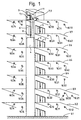
- the elevators can also easily different or a different number of Operate floors. With 3.2 here is the ground floor designated.
- the elevators each have a cabin 4 that two sides are provided with automatic doors 5, 6 and one each in a machine room motor drive 7.1 and 7.2 are moved in the shaft 8. Of course, the cabins can be in a simpler Execution also only on one side with one door be provided. Inside the cabins 4 there is a usual panel, not shown, with keys for entering calls, and, depending on the version, also with buttons for Opening and closing doors, for entering an alarm, etc.
- the elevators are controlled by an operating control 9 Accepts calls from users and as driving and Passes door control commands to the elevators 1, 2, controlled.
- Fire alarms 10.11 to 10.75 monitor the temperature and smoke development.
- the Fire alarms also detect the escape routes from the elevators outdoors or a safe place to stay, like this in the Ground floor indicated with fire alarms 10.26 and 10.27 is. Smaller buildings are used for cost reasons occasionally only one fire alarm per floor Installed. Near the operations control 9, for example, is even in the same control cabinet the controller 11 with simulator 11.1, which is described below is called fire control.
- the also as Fire alarm designated fire or danger reports from Fire alarms are in a not shown Fire alarm center or directly to the fire control system 11 reported. To avoid false alarms Hazard reports are only considered valid if optionally at least two fire alarms per floor address and / or the reports about a certain Minimum period of ten seconds, for example queue continuously.
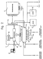
- Fig. 2 shows the fire control 11 with the Simulator 11.1 according to the invention, inputs 12.1 to 12.8 for fire alarms or fire reports, one Microprocessor 13 and with the operational control 9 connected outputs 14. Expediently also the outputs of the operating control 9 via the Fire control 11 led to a simple priority intervention in the control of drives 7.1, 7.2 and doors 5, 6. In normal operation the commands of the operating control 9 remain unchanged forwarded. Furthermore, the fire control 11 has one Socket 16, to which a monitor 17 can be connected, to display the state of the fire control 11.
- the fire control unit 11 can have a memory 18 in which the incoming fire reports as well as issued travel commands are stored chronologically in order later the fire and elevator behavior to be able to understand.
- the memory 18 can also do this serve, other signals relevant to the operation of the Operation control 9 to save.
- Via the socket 16 can an external computer can also be connected to the stored data takes over.
- this external Computer e.g. a laptop, the fire control system 11 also at any time by simply changing their configuration or their parameters new conditions in the building immediately and be optimally adapted.
- Fire alarms represent alarm messages on the Levels 1 to 7.
- the fire at 12.8 from the entrance further floors e.g. also the engine room of the Reproduces elevator or by other hazard detectors can be activated.
- the fire operation is also at isolated arrival of the building fire alarm at the entrance 12.8 activated.
- step S2 shows an example of a flow chart of FIG Fire control 11 with simulated fire situations certain operating states of an elevator car 4.
- Step S1 is the arrival of at least one simulated one Fire message shown.
- step S2 the Operating state of the elevator car 4 checked. if the Elevator car 4 stands the test gives a yes symbolized exit. In this fire situation, the Fire control 11 from step S15, in which the Doors of elevator car 4 open and the elevator out Operation.
- the elevator maintenance staff can the elevator car 4 via an external computer issued so that the elevator car 4 when a Fire alarm continues.
- This operating status is in step S2 checked. The test gives you a no symbolized output that leads to step S3.
- Step S3 takes the operating control 9 still simulated Incoming / outside calls and leads them in step S4 until the next one due to internal / external calls Stop in test mode without passengers. Then in Step S5 the fire message that arrived in step S1 checked. If it is only a fire report from "Fire building" class, for example at the entrance 12.8 the test results in a yes Output. In this fire situation, the Fire control 11 from step S15, in which the Doors of elevator car 4 open and the elevator out Operation.
- Step S5 At least one fire class of another class, for example at least one fire detection of the entrances Recognizes 12.1 to 12.7, the test ends in step S5 an output symbolized with No, whereby as in step S6 showed the floor and cabin doors on the Stop floor can not be opened. Then in Step S7 deleted and opened the calls still set Switched preference, in which, depending on the class Fire detection the elevator car 4 to certain safe Stops, so-called fire stops is controlled. In step S8 it is checked whether for each fire stop a fire message is pending. The exam can be answered with yes symbolized output result. In this fire situation the fire control 11 executes step S9 in which the elevator car 4 a move command to the most appropriate Fire stop is issued.
- step S14 If during the Evacuation trip a fire report to be approached If the fire stop arrives, the test results in step S14 an output symbolized with Yes. In this The fire control 11 leads the fire situation again Step S8 and as shown above from the Steps S9, S10 or S11 to S14 resulting in step S8 out. If the evacuation trip from the the fire stop to be approached is feasible Check an exit marked yes. In this Fire situation, the fire control 11 leads the step S15 off, in which the doors of the elevator car 4 are opened and the elevator is put out of operation. After the step S15, in step S16 the elevator users are informed of the Fire, for example, by loudspeaker announcement and / or visual display informs. After the fire, with step S17 the elevator system back to normal operation switched.
- Fire situations in certain operating conditions of the Elevator cabs 4 are not one example Fire report regarding main stop at on the main stop standing elevator car or one not the main stop Fire report concerned outside of the main stop standing elevator car or one that concerns the main stop Fire detection when the elevator car is standing or at the above Fire reports and moving elevator car.
- the possible fire situations are self-evident in the 4 and shown with A1 to E5 designated.
- A1 to E is the position of the Shown when the fire alarm arrives, a distinction is made between standing and moving Elevator or between open and closed door.
- the Columns 1 to 5 are the fire alarm situations or that of floors hit by fire alarms.
- E1 possible fire situations can be individual, essential Fire situations are selected and checked.
Landscapes
- Maintenance And Inspection Apparatuses For Elevators (AREA)
- Indicating And Signalling Devices For Elevators (AREA)
Abstract
Description
- Fig. 1
- eine schematische Gesamtansicht einer Aufzugsanlage,
- Fig. 2
- die Ansicht einer Brandfallsteuerung mit einer Einrichtung zur Simulation von Brandmeldungen,
- Fig. 3
- ein Ablaufdiagramm einer Brandfallsteuerung und
- Fig. 4
- ein Matrixdiagramm mit simulierten Brandsituationen.
Claims (5)
- Einrichtung zur Kontrolle einer Brandfallsteuerung (11) zur Evakuierung von Fahrgästen einer Aufzugsanlage mit einer von den Fahrgästen benutzten Aufzugskabine (4), welche Einrichtung bei Vorliegen mindestens einer über Eingänge (12.1 bis 12.8) zuführbaren Brandmeldung einen Fahrbefehl in eine Evakuierungs-Haltestelle vorgibt, wobei ein Simulator (11.1) vorgesehen ist, mittels dem zur Überprüfung des Verhaltens der Aufzugsanlage im Brandfall mindestens eine Brandmeldung simulierbar ist.
- Einrichtung nach Anspruch 1, dadurch gekennzeichnet, dass der Simulator (11.1) zwischen die Eingänge (12.1 bis 12.8) und die Brandfallsteuerung (11) geschaltet ist.
- Einrichtung nach den Ansprüchen 1 oder 2, dadurch gekennzeichnet, dass der Simulator (11.1) manuell oder per Programm bedienbar ist.
- Einrichtung nach Anspruch 3, dadurch gekennzeichnet, dass der Simulator (11.1) steuerbare Schaltelemente aufweist, mittels denen die Eingänge (12.1 bis 12.8) an die Brandfallsteuerung (11) anschaltbar sind.
- Einrichtung nach einem der vorhergehenden Ansprüche, dadurch gekennzeichnet, dass das Verhalten der Aufzugsanlage bei jeder simulierten Brandsituation (A1 bis E5) manuell oder per Programm protokollierbar ist.
Priority Applications (1)
| Application Number | Priority Date | Filing Date | Title |
|---|---|---|---|
| EP00103772A EP1033341B1 (de) | 1999-03-03 | 2000-02-23 | Einrichtung zur Kontrolle einer Brandfallsteuerung einer Aufzugsanlage |
Applications Claiming Priority (3)
| Application Number | Priority Date | Filing Date | Title |
|---|---|---|---|
| EP99810183 | 1999-03-03 | ||
| EP99810183 | 1999-03-03 | ||
| EP00103772A EP1033341B1 (de) | 1999-03-03 | 2000-02-23 | Einrichtung zur Kontrolle einer Brandfallsteuerung einer Aufzugsanlage |
Publications (2)
| Publication Number | Publication Date |
|---|---|
| EP1033341A1 true EP1033341A1 (de) | 2000-09-06 |
| EP1033341B1 EP1033341B1 (de) | 2003-10-22 |
Family
ID=29286291
Family Applications (1)
| Application Number | Title | Priority Date | Filing Date |
|---|---|---|---|
| EP00103772A Expired - Lifetime EP1033341B1 (de) | 1999-03-03 | 2000-02-23 | Einrichtung zur Kontrolle einer Brandfallsteuerung einer Aufzugsanlage |
Country Status (4)
| Country | Link |
|---|---|
| EP (1) | EP1033341B1 (de) |
| AT (1) | ATE252513T1 (de) |
| DE (1) | DE50004118D1 (de) |
| ES (1) | ES2209699T3 (de) |
Cited By (2)
| Publication number | Priority date | Publication date | Assignee | Title |
|---|---|---|---|---|
| DE102007010432A1 (de) | 2007-03-01 | 2008-09-04 | Stadt Dortmund Stadtbahnbauamt | Ausrüstung und Steuerung zur Nutzung von Aufzügen für die Selbstrettung im Gefahrenfall |
| CN109573768A (zh) * | 2018-12-13 | 2019-04-05 | 永大电梯设备(中国)有限公司 | 一种电梯维保保护装置及电梯维保保护方法 |
Citations (2)
| Publication number | Priority date | Publication date | Assignee | Title |
|---|---|---|---|---|
| JPH0270683A (ja) * | 1988-09-02 | 1990-03-09 | Mitsubishi Electric Corp | エレベータ試験装置 |
| US5027299A (en) * | 1988-08-04 | 1991-06-25 | Mitsubishi Denki Kabushiki Kaisha | Elevator testing apparatus |
-
2000
- 2000-02-23 AT AT00103772T patent/ATE252513T1/de not_active IP Right Cessation
- 2000-02-23 DE DE50004118T patent/DE50004118D1/de not_active Expired - Lifetime
- 2000-02-23 ES ES00103772T patent/ES2209699T3/es not_active Expired - Lifetime
- 2000-02-23 EP EP00103772A patent/EP1033341B1/de not_active Expired - Lifetime
Patent Citations (2)
| Publication number | Priority date | Publication date | Assignee | Title |
|---|---|---|---|---|
| US5027299A (en) * | 1988-08-04 | 1991-06-25 | Mitsubishi Denki Kabushiki Kaisha | Elevator testing apparatus |
| JPH0270683A (ja) * | 1988-09-02 | 1990-03-09 | Mitsubishi Electric Corp | エレベータ試験装置 |
Non-Patent Citations (1)
| Title |
|---|
| PATENT ABSTRACTS OF JAPAN vol. 014, no. 251 (M - 0979) 29 May 1990 (1990-05-29) * |
Cited By (3)
| Publication number | Priority date | Publication date | Assignee | Title |
|---|---|---|---|---|
| DE102007010432A1 (de) | 2007-03-01 | 2008-09-04 | Stadt Dortmund Stadtbahnbauamt | Ausrüstung und Steuerung zur Nutzung von Aufzügen für die Selbstrettung im Gefahrenfall |
| CN109573768A (zh) * | 2018-12-13 | 2019-04-05 | 永大电梯设备(中国)有限公司 | 一种电梯维保保护装置及电梯维保保护方法 |
| CN109573768B (zh) * | 2018-12-13 | 2023-06-16 | 永大电梯设备(中国)有限公司 | 一种电梯维保保护装置及电梯维保保护方法 |
Also Published As
| Publication number | Publication date |
|---|---|
| EP1033341B1 (de) | 2003-10-22 |
| ES2209699T3 (es) | 2004-07-01 |
| ATE252513T1 (de) | 2003-11-15 |
| DE50004118D1 (de) | 2003-11-27 |
Similar Documents
| Publication | Publication Date | Title |
|---|---|---|
| US5557546A (en) | Data acquisition system for the analysis of elevator trouble | |
| EP1045810B1 (de) | Verfahren zur durchführung von in bestimmten abständen wiederkehrenden wartungsaufgaben an einer aufzugsanlage | |
| DE112011105918B4 (de) | Aufzugsicherheitssteuervorrichtung | |
| DE102004013601A1 (de) | Bewegliches Barrierenbetriebsverfahren und Vorrichtung | |
| EP0987211B1 (de) | Fernsteuerung von Aufzugsanlagen | |
| EP1119512B1 (de) | Aufzugsanlage mit einer vorrichtung zum sonderbetrieb | |
| EP3230192B1 (de) | Verfahren und vorrichtung zur inbetriebnahme einer aufzugsanlage | |
| EP3814267B1 (de) | Sicherheitsschaltsystem und verfahren zum umschalten einer aufzugsanlage zwischen einem normal- und einem inspektionsbetriebsmodus | |
| WO2019219406A1 (de) | Inspektionssteuerungssystem einer aufzugsanlage sowie verfahren zum umschalten einer aufzugsanlage zwischen einem normal- und einem inspektionsbetrieb | |
| DE69711541T2 (de) | Überwachung eines handbetriebenen Aufzugstürsystems | |
| DE102019200351A1 (de) | Türbetriebssteuerung | |
| DE19644127A1 (de) | Evakuierungssystem | |
| EP4126733A1 (de) | Sicherheitsüberwachungsvorrichtung und verfahren zum sicherheitsüberwachen einer aufzuganlage | |
| EP3060509B1 (de) | Sicherheitssystem für einen aufzug, aufzugsanlage und verfahren zum betreiben eines solchen sicherheitssystems | |
| EP1033341B1 (de) | Einrichtung zur Kontrolle einer Brandfallsteuerung einer Aufzugsanlage | |
| WO2021083884A1 (de) | Mobilbediengerät und verfahren zum fernsteuern einer aufzuganlage | |
| EP2876073A1 (de) | Verfahren und Vorrichtung zum Evakuieren einer Aufzugsanlage in einem Brandfall | |
| DE112014006982T5 (de) | Aufzugvorrichtung | |
| EP1004536B1 (de) | Verfahren zur Steuerung von Aufzügen beim Auftreten von Feuer oder ähnlichen Gefahren | |
| EP2253570A1 (de) | Führen eines Benutzers eines Aufzuges | |
| EP2463223B1 (de) | Vorrichtung zur Kontrolle der Anhalteposition einer Aufzugkabine | |
| DE19513851C2 (de) | Sicherheitseinrichtung für einen Umlaufaufzug zur Personenbeförderung | |
| DE102007010432A1 (de) | Ausrüstung und Steuerung zur Nutzung von Aufzügen für die Selbstrettung im Gefahrenfall | |
| WO2016096699A1 (de) | Wartung einer aufzugsanlage | |
| DE10320921B4 (de) | Positionssteuerung für Torantriebe |
Legal Events
| Date | Code | Title | Description |
|---|---|---|---|
| PUAI | Public reference made under article 153(3) epc to a published international application that has entered the european phase |
Free format text: ORIGINAL CODE: 0009012 |
|
| AK | Designated contracting states |
Kind code of ref document: A1 Designated state(s): AT BE CH CY DE DK ES FI FR GB GR IE IT LI LU MC NL PT SE |
|
| AX | Request for extension of the european patent |
Free format text: AL;LT;LV;MK;RO;SI |
|
| 17P | Request for examination filed |
Effective date: 20010217 |
|
| AKX | Designation fees paid |
Free format text: AT BE CH CY DE DK ES FI FR GB GR IE IT LI LU MC NL PT SE |
|
| GRAH | Despatch of communication of intention to grant a patent |
Free format text: ORIGINAL CODE: EPIDOS IGRA |
|
| GRAS | Grant fee paid |
Free format text: ORIGINAL CODE: EPIDOSNIGR3 |
|
| GRAA | (expected) grant |
Free format text: ORIGINAL CODE: 0009210 |
|
| AK | Designated contracting states |
Kind code of ref document: B1 Designated state(s): AT BE CH CY DE DK ES FI FR GB GR IE IT LI LU MC NL PT SE |
|
| PG25 | Lapsed in a contracting state [announced via postgrant information from national office to epo] |
Ref country code: IE Free format text: LAPSE BECAUSE OF FAILURE TO SUBMIT A TRANSLATION OF THE DESCRIPTION OR TO PAY THE FEE WITHIN THE PRESCRIBED TIME-LIMIT Effective date: 20031022 Ref country code: FI Free format text: LAPSE BECAUSE OF FAILURE TO SUBMIT A TRANSLATION OF THE DESCRIPTION OR TO PAY THE FEE WITHIN THE PRESCRIBED TIME-LIMIT Effective date: 20031022 Ref country code: CY Free format text: LAPSE BECAUSE OF FAILURE TO SUBMIT A TRANSLATION OF THE DESCRIPTION OR TO PAY THE FEE WITHIN THE PRESCRIBED TIME-LIMIT Effective date: 20031022 |
|
| REG | Reference to a national code |
Ref country code: GB Ref legal event code: FG4D Free format text: NOT ENGLISH |
|
| REG | Reference to a national code |
Ref country code: CH Ref legal event code: EP |
|
| REG | Reference to a national code |
Ref country code: IE Ref legal event code: FG4D Free format text: GERMAN |
|
| REF | Corresponds to: |
Ref document number: 50004118 Country of ref document: DE Date of ref document: 20031127 Kind code of ref document: P |
|
| GBT | Gb: translation of ep patent filed (gb section 77(6)(a)/1977) |
Effective date: 20031217 |
|
| PG25 | Lapsed in a contracting state [announced via postgrant information from national office to epo] |
Ref country code: DK Free format text: LAPSE BECAUSE OF FAILURE TO SUBMIT A TRANSLATION OF THE DESCRIPTION OR TO PAY THE FEE WITHIN THE PRESCRIBED TIME-LIMIT Effective date: 20040122 Ref country code: SE Free format text: LAPSE BECAUSE OF FAILURE TO SUBMIT A TRANSLATION OF THE DESCRIPTION OR TO PAY THE FEE WITHIN THE PRESCRIBED TIME-LIMIT Effective date: 20040122 Ref country code: GR Free format text: LAPSE BECAUSE OF FAILURE TO SUBMIT A TRANSLATION OF THE DESCRIPTION OR TO PAY THE FEE WITHIN THE PRESCRIBED TIME-LIMIT Effective date: 20040122 |
|
| PG25 | Lapsed in a contracting state [announced via postgrant information from national office to epo] |
Ref country code: LU Free format text: LAPSE BECAUSE OF NON-PAYMENT OF DUE FEES Effective date: 20040223 |
|
| PG25 | Lapsed in a contracting state [announced via postgrant information from national office to epo] |
Ref country code: MC Free format text: LAPSE BECAUSE OF NON-PAYMENT OF DUE FEES Effective date: 20040228 |
|
| ET | Fr: translation filed | ||
| REG | Reference to a national code |
Ref country code: IE Ref legal event code: FD4D |
|
| REG | Reference to a national code |
Ref country code: ES Ref legal event code: FG2A Ref document number: 2209699 Country of ref document: ES Kind code of ref document: T3 |
|
| PLBE | No opposition filed within time limit |
Free format text: ORIGINAL CODE: 0009261 |
|
| STAA | Information on the status of an ep patent application or granted ep patent |
Free format text: STATUS: NO OPPOSITION FILED WITHIN TIME LIMIT |
|
| 26N | No opposition filed |
Effective date: 20040723 |
|
| PGFP | Annual fee paid to national office [announced via postgrant information from national office to epo] |
Ref country code: FR Payment date: 20050210 Year of fee payment: 6 |
|
| PGFP | Annual fee paid to national office [announced via postgrant information from national office to epo] |
Ref country code: AT Payment date: 20050211 Year of fee payment: 6 Ref country code: NL Payment date: 20050211 Year of fee payment: 6 |
|
| PGFP | Annual fee paid to national office [announced via postgrant information from national office to epo] |
Ref country code: GB Payment date: 20050214 Year of fee payment: 6 |
|
| PGFP | Annual fee paid to national office [announced via postgrant information from national office to epo] |
Ref country code: ES Payment date: 20050218 Year of fee payment: 6 |
|
| PGFP | Annual fee paid to national office [announced via postgrant information from national office to epo] |
Ref country code: BE Payment date: 20050309 Year of fee payment: 6 |
|
| PG25 | Lapsed in a contracting state [announced via postgrant information from national office to epo] |
Ref country code: GB Free format text: LAPSE BECAUSE OF NON-PAYMENT OF DUE FEES Effective date: 20060223 Ref country code: AT Free format text: LAPSE BECAUSE OF NON-PAYMENT OF DUE FEES Effective date: 20060223 |
|
| PG25 | Lapsed in a contracting state [announced via postgrant information from national office to epo] |
Ref country code: ES Free format text: LAPSE BECAUSE OF NON-PAYMENT OF DUE FEES Effective date: 20060224 |
|
| PG25 | Lapsed in a contracting state [announced via postgrant information from national office to epo] |
Ref country code: BE Free format text: LAPSE BECAUSE OF NON-PAYMENT OF DUE FEES Effective date: 20060228 |
|
| PGFP | Annual fee paid to national office [announced via postgrant information from national office to epo] |
Ref country code: CH Payment date: 20060515 Year of fee payment: 7 |
|
| PG25 | Lapsed in a contracting state [announced via postgrant information from national office to epo] |
Ref country code: NL Free format text: LAPSE BECAUSE OF NON-PAYMENT OF DUE FEES Effective date: 20060901 |
|
| GBPC | Gb: european patent ceased through non-payment of renewal fee |
Effective date: 20060223 |
|
| NLV4 | Nl: lapsed or anulled due to non-payment of the annual fee |
Effective date: 20060901 |
|
| REG | Reference to a national code |
Ref country code: FR Ref legal event code: ST Effective date: 20061031 |
|
| PG25 | Lapsed in a contracting state [announced via postgrant information from national office to epo] |
Ref country code: CH Free format text: LAPSE BECAUSE OF NON-PAYMENT OF DUE FEES Effective date: 20070228 Ref country code: LI Free format text: LAPSE BECAUSE OF NON-PAYMENT OF DUE FEES Effective date: 20070228 |
|
| REG | Reference to a national code |
Ref country code: ES Ref legal event code: FD2A Effective date: 20060224 |
|
| REG | Reference to a national code |
Ref country code: CH Ref legal event code: PL |
|
| BERE | Be: lapsed |
Owner name: *INVENTIO A.G. Effective date: 20060228 |
|
| PG25 | Lapsed in a contracting state [announced via postgrant information from national office to epo] |
Ref country code: PT Free format text: LAPSE BECAUSE OF NON-PAYMENT OF DUE FEES Effective date: 20040322 |
|
| PG25 | Lapsed in a contracting state [announced via postgrant information from national office to epo] |
Ref country code: FR Free format text: LAPSE BECAUSE OF NON-PAYMENT OF DUE FEES Effective date: 20060228 |
|
| PGFP | Annual fee paid to national office [announced via postgrant information from national office to epo] |
Ref country code: DE Payment date: 20180219 Year of fee payment: 19 |
|
| PGFP | Annual fee paid to national office [announced via postgrant information from national office to epo] |
Ref country code: IT Payment date: 20180227 Year of fee payment: 19 |
|
| REG | Reference to a national code |
Ref country code: DE Ref legal event code: R119 Ref document number: 50004118 Country of ref document: DE |
|
| PG25 | Lapsed in a contracting state [announced via postgrant information from national office to epo] |
Ref country code: DE Free format text: LAPSE BECAUSE OF NON-PAYMENT OF DUE FEES Effective date: 20190903 |
|
| PG25 | Lapsed in a contracting state [announced via postgrant information from national office to epo] |
Ref country code: IT Free format text: LAPSE BECAUSE OF NON-PAYMENT OF DUE FEES Effective date: 20190223 |