EP1032809B1 - Objective measurement and correction of optical systems using wavefront analysis - Google Patents
Objective measurement and correction of optical systems using wavefront analysis Download PDFInfo
- Publication number
- EP1032809B1 EP1032809B1 EP97948547A EP97948547A EP1032809B1 EP 1032809 B1 EP1032809 B1 EP 1032809B1 EP 97948547 A EP97948547 A EP 97948547A EP 97948547 A EP97948547 A EP 97948547A EP 1032809 B1 EP1032809 B1 EP 1032809B1
- Authority
- EP
- European Patent Office
- Prior art keywords
- wavefront
- eye
- optical
- optical correction
- lens
- Prior art date
- Legal status (The legal status is an assumption and is not a legal conclusion. Google has not performed a legal analysis and makes no representation as to the accuracy of the status listed.)
- Expired - Lifetime
Links
- 230000003287 optical effect Effects 0.000 title claims abstract description 105
- 238000012937 correction Methods 0.000 title claims abstract description 44
- 238000005259 measurement Methods 0.000 title abstract description 32
- 238000004458 analytical method Methods 0.000 title description 23
- 210000004087 cornea Anatomy 0.000 claims description 34
- 238000000926 separation method Methods 0.000 claims description 17
- 230000005855 radiation Effects 0.000 claims description 15
- 210000001525 retina Anatomy 0.000 claims description 15
- 239000000463 material Substances 0.000 claims description 11
- 238000003384 imaging method Methods 0.000 claims description 10
- 230000007547 defect Effects 0.000 claims description 4
- 230000000007 visual effect Effects 0.000 claims description 2
- 238000012544 monitoring process Methods 0.000 claims 1
- 230000004075 alteration Effects 0.000 abstract description 31
- 238000000034 method Methods 0.000 abstract description 30
- 239000011159 matrix material Substances 0.000 description 20
- 230000008859 change Effects 0.000 description 13
- 230000004438 eyesight Effects 0.000 description 12
- 238000013459 approach Methods 0.000 description 10
- 230000006870 function Effects 0.000 description 10
- 230000008901 benefit Effects 0.000 description 8
- 210000001747 pupil Anatomy 0.000 description 7
- 238000012876 topography Methods 0.000 description 7
- 238000002679 ablation Methods 0.000 description 6
- 210000000873 fovea centralis Anatomy 0.000 description 6
- 210000001519 tissue Anatomy 0.000 description 6
- 230000004305 hyperopia Effects 0.000 description 5
- 201000006318 hyperopia Diseases 0.000 description 5
- 230000004379 myopia Effects 0.000 description 5
- 208000001491 myopia Diseases 0.000 description 5
- 230000010287 polarization Effects 0.000 description 5
- 206010020675 Hypermetropia Diseases 0.000 description 4
- 241001465754 Metazoa Species 0.000 description 4
- 238000004364 calculation method Methods 0.000 description 4
- 230000004424 eye movement Effects 0.000 description 4
- 238000006073 displacement reaction Methods 0.000 description 3
- 238000011156 evaluation Methods 0.000 description 3
- 239000007943 implant Substances 0.000 description 3
- 238000000608 laser ablation Methods 0.000 description 3
- 208000014733 refractive error Diseases 0.000 description 3
- 230000002207 retinal effect Effects 0.000 description 3
- 230000007704 transition Effects 0.000 description 3
- 208000002177 Cataract Diseases 0.000 description 2
- 238000003491 array Methods 0.000 description 2
- 238000011161 development Methods 0.000 description 2
- 230000010339 dilation Effects 0.000 description 2
- 238000005516 engineering process Methods 0.000 description 2
- 238000005286 illumination Methods 0.000 description 2
- 238000002329 infrared spectrum Methods 0.000 description 2
- 238000004519 manufacturing process Methods 0.000 description 2
- 230000003252 repetitive effect Effects 0.000 description 2
- 230000001711 saccadic effect Effects 0.000 description 2
- 238000012360 testing method Methods 0.000 description 2
- 238000001429 visible spectrum Methods 0.000 description 2
- 230000004304 visual acuity Effects 0.000 description 2
- 241000282461 Canis lupus Species 0.000 description 1
- 235000008733 Citrus aurantifolia Nutrition 0.000 description 1
- 206010063341 Metamorphopsia Diseases 0.000 description 1
- 235000011941 Tilia x europaea Nutrition 0.000 description 1
- 230000001154 acute effect Effects 0.000 description 1
- 230000003190 augmentative effect Effects 0.000 description 1
- 230000009286 beneficial effect Effects 0.000 description 1
- 230000036755 cellular response Effects 0.000 description 1
- 238000005094 computer simulation Methods 0.000 description 1
- 239000012141 concentrate Substances 0.000 description 1
- 230000001351 cycling effect Effects 0.000 description 1
- 230000003247 decreasing effect Effects 0.000 description 1
- 230000001419 dependent effect Effects 0.000 description 1
- 238000009795 derivation Methods 0.000 description 1
- 238000013461 design Methods 0.000 description 1
- 238000001514 detection method Methods 0.000 description 1
- 238000003745 diagnosis Methods 0.000 description 1
- 238000007435 diagnostic evaluation Methods 0.000 description 1
- 230000000694 effects Effects 0.000 description 1
- 230000036040 emmetropia Effects 0.000 description 1
- 210000003038 endothelium Anatomy 0.000 description 1
- 210000000981 epithelium Anatomy 0.000 description 1
- 230000001747 exhibiting effect Effects 0.000 description 1
- 230000008571 general function Effects 0.000 description 1
- 239000011521 glass Substances 0.000 description 1
- 238000002513 implantation Methods 0.000 description 1
- 238000002430 laser surgery Methods 0.000 description 1
- 239000004571 lime Substances 0.000 description 1
- 238000012886 linear function Methods 0.000 description 1
- 239000000203 mixture Substances 0.000 description 1
- 238000012986 modification Methods 0.000 description 1
- 230000004048 modification Effects 0.000 description 1
- 238000005457 optimization Methods 0.000 description 1
- 230000005043 peripheral vision Effects 0.000 description 1
- 239000002831 pharmacologic agent Substances 0.000 description 1
- 238000007634 remodeling Methods 0.000 description 1
- 230000035945 sensitivity Effects 0.000 description 1
- 238000012163 sequencing technique Methods 0.000 description 1
- 238000009416 shuttering Methods 0.000 description 1
- 239000007787 solid Substances 0.000 description 1
- 238000000638 solvent extraction Methods 0.000 description 1
- 238000004381 surface treatment Methods 0.000 description 1
- 238000001356 surgical procedure Methods 0.000 description 1
- 238000002560 therapeutic procedure Methods 0.000 description 1
- 230000002747 voluntary effect Effects 0.000 description 1
Images





Classifications
-
- A—HUMAN NECESSITIES
- A61—MEDICAL OR VETERINARY SCIENCE; HYGIENE
- A61B—DIAGNOSIS; SURGERY; IDENTIFICATION
- A61B3/00—Apparatus for testing the eyes; Instruments for examining the eyes
- A61B3/10—Objective types, i.e. instruments for examining the eyes independent of the patients' perceptions or reactions
- A61B3/1015—Objective types, i.e. instruments for examining the eyes independent of the patients' perceptions or reactions for wavefront analysis
-
- G—PHYSICS
- G01—MEASURING; TESTING
- G01J—MEASUREMENT OF INTENSITY, VELOCITY, SPECTRAL CONTENT, POLARISATION, PHASE OR PULSE CHARACTERISTICS OF INFRARED, VISIBLE OR ULTRAVIOLET LIGHT; COLORIMETRY; RADIATION PYROMETRY
- G01J1/00—Photometry, e.g. photographic exposure meter
- G01J1/42—Photometry, e.g. photographic exposure meter using electric radiation detectors
- G01J1/44—Electric circuits
-
- A—HUMAN NECESSITIES
- A61—MEDICAL OR VETERINARY SCIENCE; HYGIENE
- A61F—FILTERS IMPLANTABLE INTO BLOOD VESSELS; PROSTHESES; DEVICES PROVIDING PATENCY TO, OR PREVENTING COLLAPSING OF, TUBULAR STRUCTURES OF THE BODY, e.g. STENTS; ORTHOPAEDIC, NURSING OR CONTRACEPTIVE DEVICES; FOMENTATION; TREATMENT OR PROTECTION OF EYES OR EARS; BANDAGES, DRESSINGS OR ABSORBENT PADS; FIRST-AID KITS
- A61F9/00—Methods or devices for treatment of the eyes; Devices for putting in contact-lenses; Devices to correct squinting; Apparatus to guide the blind; Protective devices for the eyes, carried on the body or in the hand
- A61F9/007—Methods or devices for eye surgery
- A61F9/008—Methods or devices for eye surgery using laser
- A61F9/00802—Methods or devices for eye surgery using laser for photoablation
- A61F9/00804—Refractive treatments
-
- G—PHYSICS
- G01—MEASURING; TESTING
- G01J—MEASUREMENT OF INTENSITY, VELOCITY, SPECTRAL CONTENT, POLARISATION, PHASE OR PULSE CHARACTERISTICS OF INFRARED, VISIBLE OR ULTRAVIOLET LIGHT; COLORIMETRY; RADIATION PYROMETRY
- G01J1/00—Photometry, e.g. photographic exposure meter
- G01J1/02—Details
- G01J1/04—Optical or mechanical part supplementary adjustable parts
- G01J1/0407—Optical elements not provided otherwise, e.g. manifolds, windows, holograms, gratings
- G01J1/0411—Optical elements not provided otherwise, e.g. manifolds, windows, holograms, gratings using focussing or collimating elements, i.e. lenses or mirrors; Aberration correction
-
- G—PHYSICS
- G02—OPTICS
- G02B—OPTICAL ELEMENTS, SYSTEMS OR APPARATUS
- G02B21/00—Microscopes
- G02B21/0004—Microscopes specially adapted for specific applications
- G02B21/002—Scanning microscopes
- G02B21/0024—Confocal scanning microscopes (CSOMs) or confocal "macroscopes"; Accessories which are not restricted to use with CSOMs, e.g. sample holders
- G02B21/0052—Optical details of the image generation
- G02B21/0068—Optical details of the image generation arrangements using polarisation
-
- A—HUMAN NECESSITIES
- A61—MEDICAL OR VETERINARY SCIENCE; HYGIENE
- A61F—FILTERS IMPLANTABLE INTO BLOOD VESSELS; PROSTHESES; DEVICES PROVIDING PATENCY TO, OR PREVENTING COLLAPSING OF, TUBULAR STRUCTURES OF THE BODY, e.g. STENTS; ORTHOPAEDIC, NURSING OR CONTRACEPTIVE DEVICES; FOMENTATION; TREATMENT OR PROTECTION OF EYES OR EARS; BANDAGES, DRESSINGS OR ABSORBENT PADS; FIRST-AID KITS
- A61F9/00—Methods or devices for treatment of the eyes; Devices for putting in contact-lenses; Devices to correct squinting; Apparatus to guide the blind; Protective devices for the eyes, carried on the body or in the hand
- A61F9/007—Methods or devices for eye surgery
- A61F9/008—Methods or devices for eye surgery using laser
- A61F2009/00844—Feedback systems
- A61F2009/00846—Eyetracking
-
- A—HUMAN NECESSITIES
- A61—MEDICAL OR VETERINARY SCIENCE; HYGIENE
- A61F—FILTERS IMPLANTABLE INTO BLOOD VESSELS; PROSTHESES; DEVICES PROVIDING PATENCY TO, OR PREVENTING COLLAPSING OF, TUBULAR STRUCTURES OF THE BODY, e.g. STENTS; ORTHOPAEDIC, NURSING OR CONTRACEPTIVE DEVICES; FOMENTATION; TREATMENT OR PROTECTION OF EYES OR EARS; BANDAGES, DRESSINGS OR ABSORBENT PADS; FIRST-AID KITS
- A61F9/00—Methods or devices for treatment of the eyes; Devices for putting in contact-lenses; Devices to correct squinting; Apparatus to guide the blind; Protective devices for the eyes, carried on the body or in the hand
- A61F9/007—Methods or devices for eye surgery
- A61F9/008—Methods or devices for eye surgery using laser
- A61F2009/00861—Methods or devices for eye surgery using laser adapted for treatment at a particular location
- A61F2009/00872—Cornea
-
- A—HUMAN NECESSITIES
- A61—MEDICAL OR VETERINARY SCIENCE; HYGIENE
- A61F—FILTERS IMPLANTABLE INTO BLOOD VESSELS; PROSTHESES; DEVICES PROVIDING PATENCY TO, OR PREVENTING COLLAPSING OF, TUBULAR STRUCTURES OF THE BODY, e.g. STENTS; ORTHOPAEDIC, NURSING OR CONTRACEPTIVE DEVICES; FOMENTATION; TREATMENT OR PROTECTION OF EYES OR EARS; BANDAGES, DRESSINGS OR ABSORBENT PADS; FIRST-AID KITS
- A61F9/00—Methods or devices for treatment of the eyes; Devices for putting in contact-lenses; Devices to correct squinting; Apparatus to guide the blind; Protective devices for the eyes, carried on the body or in the hand
- A61F9/007—Methods or devices for eye surgery
- A61F9/008—Methods or devices for eye surgery using laser
- A61F2009/00878—Planning
- A61F2009/0088—Planning based on wavefront
-
- G—PHYSICS
- G01—MEASURING; TESTING
- G01J—MEASUREMENT OF INTENSITY, VELOCITY, SPECTRAL CONTENT, POLARISATION, PHASE OR PULSE CHARACTERISTICS OF INFRARED, VISIBLE OR ULTRAVIOLET LIGHT; COLORIMETRY; RADIATION PYROMETRY
- G01J1/00—Photometry, e.g. photographic exposure meter
- G01J1/42—Photometry, e.g. photographic exposure meter using electric radiation detectors
- G01J1/44—Electric circuits
- G01J2001/4446—Type of detector
- G01J2001/448—Array [CCD]
Definitions
- the invention relates generally to optical aberration measurement and correction, and more particularly to the objective measurement and correction of optical systems having a real image focus such as human and animal eyes.
- Optical systems having a real image focus can receive collimated light and focus it at a point.
- Such optical systems can be found in nature, e.g., human and animal eyes, or can be man-made, e.g., laboratory systems, guidance systems, etc. In either case, aberrations in the optical system can affect the system's performance.
- the human eye will be used to explain this problem.
- a perfect or ideal eye 100 is shown diffusely reflecting an impinging light beam (not shown for sake of clarity) from the back of its retina 102 (i.e., the fovea centralis 103) through the eye's optics to include lens 104 and cornea 106.
- the reflected light represented by arrows 108 exits eye 100 as a sequence as of plane waves, one of which is represented by straight line 110.
- an eye normally has aberrations that cause deformation or distortion of the wave exiting the eye. This is shown by way of example in FIG.
- aberrated eye 120 diffusely reflects an impinging light beam (again not shown for sake of clarity) from the back of its retina 122 of the fovea centralis 123 through lens 124 and cornea 126.
- reflected light 128 exits eye 120 as a sequence of distorted wavefronts, one of which is represented by wavy line 130.
- the amount of corrective treatment is typically determined by placing spherical and/or cylindrical lenses of known refractive power at the spectacle plane (approximately 1.0-1.5 centimeters anterior to cornea 126) and asking the patient which lens or lens combination provides the clearest vision.
- Penney et al. One method of measuring ocular refractive errors is disclosed by Penney et al. in "Spatially Resolved Objective Autorefractometer," U.S. Patent No. 5,258,791, issued Nov. 2, 1993.
- Penney et al. teach the use of an autorefractometer to measure the refraction of the eye at numerous discrete locations across the corneal surface.
- the autorefractometer is designed to deliver a narrow beam of optical radiation to the surface of the eye, and to determine where that beam strikes the retina using a retinal imaging system. Both the angle of the beam's propagation direction with respect to the optical axis of the system and the approximate location at which the beam strikes the corneal surface of the eye are independently adjustable.
- a small uncertainty or error in the location of the beam's point of incidence on the cornea exists due to the curved corneal surface.
- the refraction of the eye corresponding to that surface point can be determined by adjusting the angle at which the beam strikes the cornea until the beam refracted on to the iris strikes the fovea centralis. Adjustment of the beam angle of propagation can be accomplished either manually by the patient or automatically by the autorefractometer if a feedback loop involving a retinal imaging component is incorporated.
- Penney et al. further teach the use of the autorefractometer measurements in determining the appropriate corneal surface reshaping to provide emmetropia. This is accomplished by first obtaining accurate measurement of corneal surface topography (using a separate commercially available device). A mathematical analysis is then performed using the initial corneal topography at each surface reference point, the measured refraction at each surface point, and Snell's law of refraction, to determine the required change in surface contour at each reference point. The contour changes at the various reference points are then combined to arrive at a single reshaping profile to be applied across the full corneal surface.
- a second limitation to the approach described by Penney et al. is that test points on the corneal surface are examined sequentially. Eye motion during the examination, either voluntary or involuntary, could introduce substantial errors in the refraction measurement. Penney et al. attempt to provide detection of such eye movement by deliberately including measurement points outside the pupil, i.e., in the corneal region overlying the iris, where the return from the retina will obviously be zero at specific intervals in the examination sequence. However, this approach may still allow substantial undetected eye movement error between such iris reference points.
- the Hartmann-Shack wavefront sensor disclosed by Liang et al. includes two identical layers of cylindrical lenses with the layers arranged so that the lenses in each layer are perpendicular to one another. In this way, the two layers act like a two-dimensional array of spherical lenslets that divide the incoming light wave into subapertures. The light through each subaperture is brought to focus in the focal plane of the lens array where a charge coupled device (CCD) image module resides.
- CCD charge coupled device
- the system of Liang et al. is calibrated by impinging an ideal plane wave of light on the lenslet array so that a reference or calibrating pattern of focus spots is imaged on the CCD. Since the ideal wavefront is planar, each spot related to the ideal wavefront is located on the optical axis of the corresponding lenslet. When a distorted wavefront passes through the lenslet array, the image spots on the CCD are shifted with respect to the reference pattern generated by the ideal wavefront. Each shift is proportional to the local slopes, i.e., partial derivatives, of the distorted wavefront which can be used to reconstruct the distorted wavefront, by means of modal wavefront estimation with Zernike polynomials.
- Liang et al. can only achieve wavefront measurement for a relatively small class of patients. Such patients can have, at most, mildly distorted vision.
- WO9201417 discloses an automated binocular vision measurement system that measures the refractions of each eye, the topography of the cornea, and the holographic corneal depth.
- a computer assesses the visual characteristics and performs optical optimization calculations to determine the optimal corneal shapes that would provide the person with precise vision capabilities.
- An optimal closed pattern trace of low power level laser energy induces the malaxation of the corneal tissue.
- Laser energy is delivered to a stromal target in the cornea between the epithelium and endothelium. Predetermined parameters are measured using a moire technique. Data representive of an input fringe pattern which includes signal information of the fringe and noise is filtered in a Fourier transform technique to remove noise and back-ground.
- W09528989 discloses a surface treatment laser beam delivery and tracking system.
- the laser generates laser light along a path at an energy level suitable for treating a surface.
- An optical translator shifts the path onto a resulting beam path.
- An optical angle adjuster changes the angle of the resulting beam path relative to the original path such that the laser light is incident on the surface to be treated.
- a motion sensor transmits light energy to the surface and receives reflected light energy from the surface via the optical angle adjuster. The tight energy travels on a parallel path to the shifted beam through the optical angle adjuster.
- the motion sensor detects movement of the surface relative to the original path and generates error control signals indicative of the movement.
- the optical angle adjuster responds to the error control signals to change the angle of the resulting beam path.
- US4,641,962 discloses an aberration measurement system in which a light beam from a light source is provided at the image plane position of a lens to be examined and where the light beam passes through the lens to be examined, is separated into a plurality of light rays in a plane perpendicular to the optical axis of the lens to be examined, and the position of each light beam is detected at a position which is spaced apart from a position optically conjugate with said image plane position with respect to the lens to be examined and at which the plurality of light rays can be separated from one another.
- Another object of the present invention is to provide for the objective measurement of ocular aberrations having a dynamic range that can cope with large amounts of such aberrations so as to be useful in practical applications.
- Still another object of the present invention to provide a method and system for objectively measuring ocular aberrations using a wavefront analyzer of simple and inexpensive design.
- an energy source generates a beam of radiation.
- Optics disposed in the path of the beam, direct the beam through a focusing optical system, e.g., an eye, that has a rear portion thereof functioning as a diffuse reflector.
- the beam is diffusely reflected back from the rear portion as a wavefront of radiation that passes through the focusing optical system to impinge on the optics.
- the optics project the wavefront to a wavefront analyzer in direct correspondence with the wavefront as it emerges from the focusing optical system.
- a wavefront analyzer is disposed in the path of the wavefront projected from the optics and calculates distortions of the wavefront as an estimate of ocular aberrations of the focusing optical system.
- the wavefront analyzer includes a wavefront sensor coupled to a processor that analyzes the sensor data to reconstruct the wavefront to include the distortions thereof.
- the radiation is optical radiation and the wavefront sensor is implemented using a plate and a planar array of light-sensitive cells.
- the plate is generally opaque but that has an array of light transmissive apertures that selectively let impinging light therethrough.
- the plate is disposed in the path of the wavefront so that portions of the wavefront pass through the light transmissive apertures.
- the planar array of cells is arranged parallel to and spaced apart from the plate by a selected distance. Each portion of the wavefront passing through one of the light transmissive apertures illuminates a geometric shape covering a unique plurality of cells.
- the wavefront sensor comprises a two-dimensional array of spherical lenslets and a planar array of cells.
- the array of lenslets defines a focal plane that is a focal length away therefrom.
- the array of lenslets is disposed in the path of the wavefront where portions of the wavefront pass therethrough.
- the planar array of cells is arranged parallel to and spaced apart from the array of lenslets by a selected distance independent of the focal length. Similar to the first embodiment wavefront sensor, each portion of the wavefront illuminates a geometric shape covering a unique plurality of cells. Regardless of which wavefront sensor is used, the distance between the planar array of cells and the opaque plate, or the array of lenslets, can be varied to adjust the slope measurement gain of the wavefront sensor and thereby improve the dynamic range of the system.
- the focusing optics includes first and second lenses maintained in fixed positions in the path of the beam and wavefront.
- An arrangement of optical elements is disposed between the lenses in the path of the beam and the wavefront. The optical elements are adjustable to change the optical path length between the lenses.
- the distortions are converted to an optical correction which, if placed in the path of the wavefront, causes the wavefront to appear approximately as a plane wave.
- the optical correction can be in the form of a lens or an amount of corneal material ablated from the eye.
- the present invention will be described with respect to diagnosing and correcting a human eye.
- teachings of the present invention are applicable to any optical system having a real image focus that can (or can be adapted to) diffusely reflect a focused spot of radiation from a rear portion of the optical system back through the optical system as a wavefront of radiation.
- the present invention can be used with human or animal eyes of patients that may be alive or dead, or any man-made optical system satisfying the criteria regarding the real image focus.
- Distorted wavefront 130 can be described mathematically as W(x,y).
- One method of measuring the distortions in wavefront 130 is to determine the spatial separation ⁇ z between a reference plane 131 (analogous to ideal wavefront 110) at a known distance z 0 from the eye at each (x,y) point of distorted wavefront 130 as the leading edge of wavefront 130 traverses distance z 0 .
- Az measurements define the inappropriate optical path differences due to the aberrations in the test eye.
- the appropriate correction consists of removing these optical path differences. Ideally, such correction is performed at reference plane 131.
- the amount of material removed or added at each (x,y) coordinate can be calculated directly if the refractive index of the material in question is known.
- wavefront analysis can be performed repetitively during the procedure to provide feedback information as to the appropriate endpoint of the procedure.
- the differences ⁇ z(x,y) between the distorted and ideal wavefronts are the consequence of the aberrations in the eye.
- Ablation could then be carried out discretely at each (x,y) coordinate along the cornea by a laser beam delivery and eye tracking system such as disclosed in U.S. Patent Application Serial No. 08/232,615, filed April 25, 1994, owned by the same assignee as the present invention, and which is incorporated herein by reference.
- the appropriate corneal ablation depth at any (x,y) transverse coordinate is, to within a small error, given by ⁇ z x , y / n c - 1 where n c is the refractive index of corneal tissue or 1.3775.
- the method described in detail below calculates Az(x,y) by first measuring the local slopes in wavefront 130, i.e., ⁇ W(x,y)/ ⁇ x and ⁇ W(x,y)/ ⁇ y, at a number of points in the transverse x and y directions in reference plane 131 and then generating a mathematical description of W(x,y) having slopes in best possible agreement with the experimentally determined values.
- E x (x 0 ,y 0 ) x' -x 0 .
- E y (x 0 ,y 0 ) y'-y 0 . If significant, these transverse errors can be compensated for by laterally displacing the aberration correction calculated at each (x,y) coordinate by the amounts E x (x,y) and E y (x,y).
- the transverse error under most circumstances will be negligible.
- the error will be zero at the origin where the corneal tissue and reference plane 131 are tangent.
- the tissue is approximately spherical with a radius of curvature of approximately 7.5-8.0 mm.
- the corrective treatment radius is typically no more than 3 mm, and local wavefront radius of curvature will almost always exceed 50 mm (a 20 diopter refractive error).
- the transverse error E at a 3 mm treatment radius for a local wavefront radius of curvature of 50 mm is less than 40 mm.
- wavefront analysis can also be used repetitively during the corrective procedure to provide useful feedback information.
- One example of such use would be in cataract surgery where wavefront analysis could be performed on the eye following placement of an intra-ocular lens implant (IOL). The analysis could help identify whether the appropriate refractive power IOL has been inserted, or whether a different refractive power IOL should be used.
- Another example of repetitive wavefront analysis would be during keratoplastic procedures where the cornea of the eye is deliberately distorted by altering the mechanical tension around the periphery thereof.
- repetitive wavefront analysis could be used to refine the degree of induced tension change at each point around the cornea thereby providing the tool to obtain optimum surface curvature for best visual acuity.
- the amount of spatial separation of component portions of wavefront 130 relative to the corresponding component portions of a planar or ideal wavefront must be measured. It is the system and method of the present invention that allows such separation to be objectively and accurately measured for even substantially aberrated eyes including those exhibiting severe defects such as severe myopia or hyperopia.
- the patient's pupil should ideally be dilated to approximately 6 millimeters or more, i.e., the typical size of a human pupil in low light.
- the eye is evaluated while it is using the greatest area of the cornea so that any correction developed from such measurement takes into account the largest usable corneal area of the patient's eye.
- Dilation can be brought about naturally by implementing the measurement portion of the present invention in a low light environment such as a dimly lit room. Dilation can also be induced through the use of pharmacologic agents.
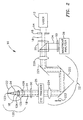
- System 10 includes laser 12 for generating the optical radiation used to produce a small-diameter laser beam.
- Laser 12 is typically a laser generating collimated laser light (represented by dashed lines 14) of a wavelength and power that is eye-safe.
- appropriate wavelengths would include the entire visible spectrum from approximately 400-710 nanometers and the near infrared spectrum from approximately 710-1000 nanometers. While operation in the visible spectrum is generally preferable (since these are the conditions in which the eye operates), the near infrared spectrum may offer advantages in certain applications.
- the patient's eye may be more relaxed if the patient does not know measurement is taking place.
- power should be restricted in ophthalmic applications to eye-safe levels.
- eye-safe exposure levels can be found in the U.S. Federal Performance Standard for Laser Products. If the analysis is to be performed on an optical system other than the eye, the examination wavelength range logically should incorporate the intended performance range of the system.
- an iris diaphragm 16 can be used to block all of laser light 14 except for laser beam 18 of a size desired for use by the present invention.
- laser beam 18 can have a diameter in the range of approximately 0.5-4.5 millimeters with 1-3 millimeters being typical. A badly aberrated eye requires a smaller diameter beam while an eye with only slight aberrations can be evaluated with a larger diameter beam.
- a lens (not shown) can be positioned in the beam path to optimize collimation.
- Laser beam 18 is a polarized beam that is passed through a polarization sensitive beam splitter 20 enroute to being directed to a focusing optical train 22.
- Optical train 22 operates to focus laser beam 18 through the optics of eye 120 (e.g., cornea 126, pupil 125 and lens 124) to the back of the eye's retina 122.
- lens 124 may not be present for a patient that has undergone a cataract procedure, however, this does not affect the present invention.
- optical train 22 images laser beam 18 as a small spot of light at or near the eye's fovea centralis 123 where the eye's vision is most acute.
- the small spot of light could be reflected off another portion of retina 122 in order to determine aberrations related to another aspect of one's vision. For example, if the spot of light were reflected off the area of retina 122 surrounding the fovea centralis 123, aberrations specifically related to one's peripheral vision could be evaluated. In all cases, the spot of light is sized to form a near-diffraction limited image on retina 122. Thus, the spot of light produced by laser beam 18 at fovea centralis 123 does not exceed approximately 100 micrometers in diameter and, typically, is on the order of 10 micrometers.
- wavefront 24 The diffuse reflection of laser beam 18 back from retina 122 is represented in FIG. 2 by solid lines 24 indicative of the wavefront of radiation that passes back through eye 120.
- Wavefront 24 impinges on and is passed through optical train 22 enroute to polarization sensitive beam spitter 20.
- Wavefront 24 is depolarized relative to laser beam 18 due to reflection and refraction as wavefront 24 comes off retina 122. Accordingly, wavefront 24 is turned at polarization sensitive beam splitter 20 and directed to a wavefront analyzer 26 such as a Hartmann-Shack (H-S) wavefront analyzer.
- wavefront analyzer 26 measures the slopes of wavefront 24, i.e., the partial derivatives with respect to x and y, at a number of (x,y) transverse coordinates. This partial derivative information is then used to reconstruct or approximate the original wavefront with a mathematical expression such as a weighted series of Zernike polynomials.
- stray radiation may be sufficiently small when compared to the radiation returning from the desired target (e.g., retina 122) so that the above polarization specifications are unnecessary.
- the present invention is able to adapt to a wide range of vision defects and as such achieves a new level of dynamic range in terms of measuring ocular aberrations.
- Dynamic range enhancement is accomplished with optical train 22 and/or the wavefront sensor portion of wavefront analyzer 26 as will now be explained.
- optical train 22 includes a first lens 220, a flat mirror 221, a Porro mirror 222 and a second lens 224 all of which lie along the path of laser beam 18 and wavefront 24.
- First lens 220 and second lens 224 are identical lenses maintained in fixed positions.
- Porro mirror 222 is capable of linear movement as indicated by arrow 223 to change the optical path length between lenses 220 and 224.
- the present invention is not limited to the particular arrangement of flat mirror 221 and Porro mirror 222 and that other optical arrangements could be used between lenses 220 and 224 to change the optical path length therebetween.
- the zero position" of Porro mirror 222 can be identified by replacing eye 120 in FIG. 2 by a broad beam source (not shown) of collimated light to simulate a perfect plane wave.
- a broad beam source could be realized by a laser beam expanded by a beam telescope to the diameter that will cover the imaging plane of wavefront analyzer 26 and adjusting Porro mirror 222 until wavefront analyzer 26 detects the light as being collimated.
- the changes in optical path length brought about by Porro mirror 222 can be calibrated in diopters to provide an approximate spherical dioptric correction as will be explained further below.
- the dynamic range of system 10 can be further improved by utilizing a preferred embodiment wavefront analyzer to include an improved wavefront sensor arrangement.
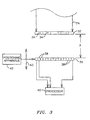
- the wavefront analyzer includes an opaque imaging plate 32 having an array of holes 34 passing therethrough, a planar array 36 of light-sensitive cells such as charge coupled device cells 38, and a processor 40 coupled to planar array 36 of cells 38.
- the combination of plate 32 and planar array 36 comprises the unique wavefront sensor of this embodiment.
- Plate 32 is maintained parallel to and spaced apart a separation distance F from planar array 36. As will be explained further below, separation distance F can be varied to adjust the gain of the sensor.
- planar array 36 is coupled to a positioning apparatus 42, e.g., a conventional motorized linear positioner having precise movement capability, that can adjust the position of planar array 36 relative to plate 32 to change separation distance F as indicated by arrow 43.
- a positioning apparatus 42 e.g., a conventional motorized linear positioner having precise movement capability
- each of holes 34 is of equal size and shape with a circle being typical owing to its ease of manufacture.
- a square array geometry is used for array of holes 34 although other array geometries can be used.
- each such wavefront piece 25 passes through hole 34 to illuminate planar array 36.
- the resulting image formed by each such wavefront piece 25 is a positive shadow of the respective hole 34.
- diffraction does occur in a way determined by the diameter D of each hole 34, the wavelength X of the light source (i.e., wavefront 24) and the separation distance F between plate 32 and planar array 36.
- the value F is varied by positioning apparatus 42 to adjust the gain based on the particular patient as will be explained further below.
- plate 32 with holes 34 could also be accomplished using a solid plate or film made from a light-sensitive material such as a photolithographic film.
- the array of holes 34 would be replaced by an array of shaped light transmissive apertures through which light passes when impinging thereon. The remainder of such a plate or film would be impervious to light.
- the advantage achieved by such an embodiment is that the light transmissive apertures could easily be made to conform to any desired shape.
- each wavefront piece 25 measures the amount of angular deflection of each wavefront piece 25 relative to a wavefront piece that would result from a planar wavefront. This is best seen in FIG. 4 where the calibration or planar wavefront of light results in a wavefront piece represented by arrow 112 (normal to plate 32) that illuminates a geometric spot 114 on planar array 36.
- wavefront 24 represents a distorted wavefront as described above
- wavefront piece 25 will exhibit an amount of angular deflection relative to (calibrating) wavefront piece 112.
- the angular deflection causes wavefront piece 25 to illuminate a geometric spot 27 on planar array 36 that is offset from (calibrating) spot 114.
- the amount of offset is measured relative to the centroids 116 and 29 of spots 114 and 27, respectively.
- centroid 29 is (typically) deflected in both the x and y directions of array 36.
- the angular deflection in each of the x and y directions is given by ⁇ x/F and ⁇ y/F, respectively.
- lenses 220 and 224 are identical as mentioned above. However, in certain applications it may be desirable to magnify or minify the wavefront at the wavefront sensor. This can be accomplished by using lenses 220 and 224 of different focal lengths and adjusting the apparatus dimensions accordingly.
- the object plane of the apparatus should ideally be tangent to the corneal surface which can be achieved by a variety of means. Thus, each point at the object plane of optical train 22 very nearly corresponds to the same point on the cornea (although since the cornea is curved, there will be a slight lateral displacement). Plate 32 (or the imaging plane of any wavefront sensor portion) of wavefront analyzer 26 is positioned at the focal plane of lens 220.
- the object plane is always imaged on plate 32 in direct correspondence with the wavefront image emerging from cornea 126. This will be true regardless of the optical path length between lenses 220 and 224.
- This structure there are several advantages to this structure, one of which is that there are very good planar arrays of light-sensitive cells that are commercially available to image an area corresponding to the 6 millimeter central circular region of the cornea. Additional advantages will now be explained.
- plate 32 (or the imaging plane of any wavefront sensor portion of wavefront analyzer 26) is to break wavefront 24 into wavefront pieces that can each be measured independently (in terms of propagation direction) at planar array 36. Since in the preferred embodiment optical train 22 does not magnify or reduce the image in the object plane, a point at the object plane corresponds to the same point at the image plane of optical train 22. With Porro mirror 222 set at its "zero position", the direction each piece of wavefront 24 is travelling at the object plane is reproduced exactly at the image plane of wavefront analyzer 26.
- the wavefront piece at the same location in the image plane will also be travelling away from the optical axis at an angle of 20°.
- the first way is to utilize a wavefront sensor with sufficiently small light-sensitive cells 38 and sufficiently large holes 34 (or any other transmissive aperture). In this way, measurement of each wavefront piece can be performed to an acceptable accuracy using a small value for F.
- the second way is to move planar array 36 along the optical axis to change the separation distance F to plate 32. For a person with a severe aberration, planar array 36 is positioned close to plate 32 to keep the projected wavefront pieces well separated and on planar array 36. For a mild aberration, planar array 36 can be moved to increase the separation distance F to plate 32 to make a more accurate measurement.
- the advantage of moving planar array 36 to change the separation distance F to plate 32 is that the wavefront analysis is easily achieved for any position.
- the third way of compensating for severe aberrations in the present invention is to change the optical path length between lenses 220 and 224. Moving Porro mirror 222 will not affect where the wavefront hits plate 32, but will change the angular deflections at which the projected wavefront pieces pass through plate 32, i.e., ⁇ x/F and ⁇ y/F. Decreasing the optical path length between lenses 220 and 224 will tend to pull the wavefront pieces toward the center of planar array 36 thereby compensating for hyperopia.
- the degree to which the angular deflection associated with each wavefront piece is altered is a linear function of its distance off the optical axis and the movement of Porro mirror 222 from its zero position.
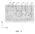
- each spot In order to accurately determine the centroids of a spot of light impinging on array 36, it is necessary to provide a fine structure of cells 38 relative to a spot size. In other words, each spot must cover a plurality of cells 38.
- a unique number of cells 38 is assigned to each hole 34.
- the "assigned areas" are designated in FIG. 5 by the heavy grid lines 39. It is to be understood that grid lines 39 are not actual physical boundaries between cells 38 but are shown simply to illustrate the unique designated areas containing a plurality of cells 38.
- Other centroid strategies can be utilized that do not necessitate such partitioning of array 36.
- the wavefront sensor of the present invention does not focus each wavefront piece to a minimum at the surface of array 36, a larger plurality of cells 38 are illuminated by each geometric spot so that the centroid of each spot can be determined to a greater precision than was previously possible.
- the present invention could also be practiced with a wavefront analyzer that replaced plate 32 (FIG. 3) with a two-dimensional array of identical spherical lenslets 33 as shown in FIG. 6.
- array 33 is positioned by positioning apparatus 42 such that separation distance F is independent of the focal length f that defines the focal plane of array 33 which is represented by dashed line 35.
- each wavefront piece e.g., wavefront piece 37
- each wavefront piece passed through a subaperture of array 33 is reduced in size (e.g., diameter) but is not necessarily brought to a minimum focus at array 36 as it would be if separation distance F were equal to focal length f.
- array 33 is positioned to concentrate the light in each wavefront piece over an area for sufficient intensity on planar array 36, yet still illuminate a substantial plurality of cells 38 (as described above) for greatest accuracy in determining the deflection of the spot's centroid.
- processor 40 computes each two-dimensional centroid of each spot generated by a wavefront 24.
- the amount of two-dimensional centroid shift (relative to the centroid of the calibrating spot) for each designated area associated with a corresponding hole 34 (or subaperture of array 33) is divided by the separation distance F to generate a matrix of local slopes of the wavefront, i.e., ⁇ W(x,y)/ ⁇ x and ⁇ W(x,y)/ ⁇ y at the (x,y) coordinates of the centers of holes 34.
- ⁇ W(x,y)/ ⁇ x ⁇ W(x,y)/ ⁇ x
- Q(x,y) ⁇ W(x,y)/ ⁇ y, respectively.
- the upper limit n on the summation is a function of the number of Zernike polynomials, i.e., the highest order, used to approximate the true wavefront.
- n m + 1 ⁇ m + 2 / 2
- Derivation of the Zernike polynomials up to an arbitrary order n is described in numerous optical texts such as the aforementioned book by Born and Wolf.
- centroid of a spot The directions of the unit normals at the center of each hole 34 are based on the centroids of the spots on cells 38. Since each spot will illuminate a plurality of cells with varying intensity, a standard amplitude-weighted centroid calculation can be used to find the center of each spot. Each centroid must be measured twice, once for perpendicular collimated light, and again for the wavefront to be analyzed. Of course, all spots are imaged simultaneously during each exposure.
- system 10 can be augmented by the addition of an eye tracker 25.
- eye tracker 25 One possible placement of eye tracker 25 is shown in FIG. 2. However, it is to be understood that eye tracker 25 could be placed elsewhere in system 10.
- One such eye tracker is disclosed in the aforementioned U.S. Patent Applicaiton Serial No. 08/232,615. In this way, wavefront analysis could be performed even during a limited amount of eye motion.
- a one-time calibration exposure can also be used to determine the relative sensitivities of the individual cells. This is made in uniform collimated light with plate 32 removed. The responses of individual cells are then recorded.
- the centroid in the collimated case serves as a dedicated origin for the particular hole.
- the shift from the "origin" for each hole to the centroid caused by wavefront 24 (as observed in this coordinate system) is determined by the direction of the wave surface corresponding to that hole.
- each P(m,n) and Q(m,n) represents the partial derivatives of W(x,y) with respect to x and y for the (x,y) coordinates of each hole 34.
- each hole 34 is assigned its dedicated area of array 36 or (i m , n ⁇ ⁇ i, j m,n ⁇ ⁇ j). This square of many light-sensitive cells is large enough that neighboring hole images never encroach, and all illumination from this hole is contained. The square contains 4 ⁇ i* ⁇ j cells.
- the surface partial derivatives P(i,j) and Q(i,j) for the array of hole centers of plate 32 are next used to calculate the appropriate Zernike polynomial weighting coefficients to describe the original wavefront W(x,y). This will now be explained by way of illustration for a 7 x 7 square array of holes 34. However, it is to be understood that other sizes and shapes of hole arrays could be used.
- the functions Z k (x,y) in equation (19) are the Zernike polynomials. There is no standard convention as to their sequence. Thus, for consistency, it is important that the same sequence is used to produce the set C k that was chosen for deriving the matrix TM . They occur in groups of the same order, which is the highest exponent in the group, with the total number of members in an order increasing with the order. For example, in a fourth order analysis, orders up to and including 4 are used (less Z 0 - the single member of order 0 that is the constant 1 which describes the reference position of the group in the z direction). Since wavefront 24 is moving along z (at the velocity of light), this "piston term" describes only an arbitrary offset in Z, and this term may be ignored. The first 5 orders (0, 1, ...,4) contain 15 functions including the piston term.
- 14 values of C k are calculated as coefficients of 14 Zernike polynomials.
- Table 1 ZERNIKE (X,Y) POLYNOMIAL EXPANSION THROUGH ORDER 4 Polynomial Order 0 Z(0) +1 dZ(0)/dx 0.0 dZ(0)/dy 0.0 Polynomial Order 1 Z(1) +y dZ(1)/dx 0.0 dZ(1)/dy +1 Z(2) +x dZ(2)/dx +1 dZ(2)/dy 0.0 Polynomial Order 2 Z(3) -1+2y 2 +2x 2 dZ(3)/dx +4x dZ(3)/dy +4y Z(4) +2xy dZ(4)/dx +2y dZ(4)/dy +2x Z(5) -y 2 +x 2 dZ(5)/dx +2x dZ
- Calculation of the ⁇ z(x,y) optical path difference information from the Zernike reconstruction of the wavefront is accomplished simply by subtracting a constant from the Zernike approximation.
- the value of the constant will depend on the desired characteristics of ⁇ z(x,y).
- transition matrix TM The development of the transition matrix TM will now be explained for the illustrated example of a 7 x 7 array of holes in plate 32.
- equation (25) gives the normal components in terms of the Zernike coefficients for a surface described by the array of 14 C's. These are exact, but it is not guaranteed that the actual total surface can be described by such an array of coefficients. Accordingly, if it is assumed that the description is within an acceptable tolerance, i.e., tolerating the errors that remain after least square error determination, then equation (26) can be considered to define the column vector C implicitly in terms of the mathematical matrix M and the measured vector PQ , both of which are known.
- the method of effecting the solution under the minimization condition is as follows.
- S ⁇ M T ⁇ M is a square and symmetric matrix, e.g., of dimensions 14 x 14 (with each element the sum of 98 products).
- Such a matrix has an inverse unless the determinant of its coefficients is zero. Since this is based on the Zernike polynomials alone, and they are all independent of each other, the determinant is non-zero, so that an inverse S -1 is defined.
- planar array 36 To evaluate the eye unambiguously, all spots illuminating planar array 36 due to a wavefront 24 must be incident on planar array 36 simultaneously. This is achieved by pulsing or shuttering the laser source (i.e., laser 12) such that pulse duration is less than the saccadic motion interval of the eye, i.e., a few milliseconds.
- the laser source could be left on continuously and wavefront 24 could be shuttered to appear as a wavefront pulse of a duration that is less than saccadic motion of the eye.
- shutter 50 could be positioned in the path of laser beam 18 before eye 120 or in the path of wavefront 24 before wavefront analyzer 26.
- FIG. 7 An implementation of the present invention suitable for clinical use is shown schematically in FIG. 7 and is referenced generally by numeral 11. Like reference numerals are used to describe elements that are the same as those described above with respect to system 10. Accordingly, the like elements and their functions will not be described further.
- a dichroic beam spitter 52 is interposed between beam spitter 20 and optical train 22 to introduce fixation target optics 60 and observation optics 70 into system 11 which are optically separated from one another by 50/50 beam spitter 54.
- fixation target optics provide eye 120 with visible light in the shape of a target.
- the visible light generated by fixation target optics 60 is reflected by dichroic beam spitter 50 and directed through optical train 22.
- fixation target optics 60 can be implemented in a variety of fashions.
- one such embodiment is shown and includes visible light source 61, light diffuser 62, target 63, field stop 64, lens 65 and iris 66.
- Light source 61 and light diffuser 62 are used to provide uniform illumination of fixation target 63.
- Field stop 64, lens 65, and iris 66 are used in conjunction with optical train 22 to present a clear image of the fixation target to (patient) eye 120.
- observation optics 70 allows a technician to view and document the eye evaluation procedure. While a variety of implementations of observation optics 70 are possible, one such implementation is shown by way of example.
- observation optics 70 includes field lens 71, lens 72, iris 73, lens 74, and camera 75.
- a ring illuminator 80 is placed in front of eye 120 to illuminate same for observation and/or filming purposes.
- the output from wavefront analyzer 26, e.g., the Zernike expansion of equation (19), can be used in a variety of ways.
- the output could be used to continually or periodically monitor the progress or effects of an ophthalmic procedure.
- the output could also be used to develop an optical correction for eye 120.
- the optical correction will make wavefront 24 appear approximately as a plane wave.
- the optical correction can be implemented in a variety of ways.
- the output of wavefront analyzer 26 is input to a processor 90 which converts the Zernike expansion of equation (19) into a form suitable for being implemented as one of the possible optical corrections. (The functions of processor 90 could also be implemented at processor 40 of wavefront analyzer 26.)
- Processor 90 could use some of the Zernike coefficients from the expansion of equation (19) to generate a standard sphero-cylindrical correction for lens grinder 92 to produce a convectional optical lens, e.g., a lens for glasses, a contact lens, etc.
- Processor 90 could also divide the Zernike reconstruction of the aberrated wavefront by the index of refraction of cornea 126 minus 1, to calculate the amount of corneal material to be ablated at each corresponding (x,y) location on the cornea.
- the amount of corneal material at each location is input to a laser beam delivery system that typically has eye tracking capability 94 such as described in the afore-mentioned U.S. Patent Application Serial No. 08/232,615.
- Laser beam delivery and eye tracker 94 is placed in line with the optical axis of system 11.
- the eye tracker portion of this element allows system 11 to respond unwanted eye motion.
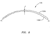
- Laser beam delivery and eye tracker 94 would typically focus short pulses or "shots" of ablating laser light at cornea 126 or eye 120 to remove the specified thickness t of material at each location. This is shown diagrammatically in FIG. 8 where the uncorrected surface of cornea 126 is referenced by numeral 126A and the corrected surface of cornea 126 after ablation is referenced by numeral 126B.
- ablation thickness t is specified across the aperture of the cornea measured, e.g., the 6 millimeter circle to which the eye's pupil was dilated during the measurement of the eye. Outside the prescribed treatment circle, a tapering blend zone of partial ablation may be added to minimize severe changes in corneal curvature and hence lessen regression.
- Laser beam delivery system 94 removes thickness t to achieve the optical correction, i.e., corrected cornea surface 126B. Note that the optical correction is not concerned with the ultimate corneal topography, but instead removes corneal material to achieve an optical correction that takes into account all ocular aberrations of the eye.
- the present invention can be used to provide corneal surface corrections other than the conventional spherical and/or cylindrical corrections.
- the advantages of the present invention are numerous. A totally objective approach is presented for measuring ocular aberrations. The approach is effective for a wide range of vision defects. Accordingly, the present invention will be of great utility in a wide variety of clinical applications.
- the calculated Zernike coefficients can be used to develop a completely objective lens prescription or a corneal correction that could be accomplished with laser ablation.
- each of the wavefront sensor embodiments provides for a greater degree of accuracy over the prior art with respect to measuring wavefront deflections. Further, the present wavefront sensor can be adjusted in terms of gain simply by adjusting the separation distance between the imaging plane of the sensor and the planar array of light-sensitive cells.
- the objective measurement of the present invention will also find great utility for a large variety of applications in which the "patient” is unable to provide feedback as required by conventional eye diagnosis.
- the present invention could be used to evaluate the eyes of any patient not possessed of demonstrative communicative skills, e.g., babies, animals, dead specimens, as well as any constructed optical system, since the present invention is an objective analysis not requiring any assessment from the "subject". All that is necessary is for the subject's eye to be properly positioned so that proper optical access to the eye can be obtained.
- the present invention could also be used in the area of identification should it be determined that each eye's Zernike coefficients are unique. Then, the present invention would find great utility in the fields of law enforcement, credit card/bank security, or any other field where positive identification would be beneficial.
Landscapes
- Health & Medical Sciences (AREA)
- Physics & Mathematics (AREA)
- Life Sciences & Earth Sciences (AREA)
- General Physics & Mathematics (AREA)
- Ophthalmology & Optometry (AREA)
- Heart & Thoracic Surgery (AREA)
- Veterinary Medicine (AREA)
- Spectroscopy & Molecular Physics (AREA)
- Optics & Photonics (AREA)
- Surgery (AREA)
- Engineering & Computer Science (AREA)
- Biomedical Technology (AREA)
- Public Health (AREA)
- General Health & Medical Sciences (AREA)
- Animal Behavior & Ethology (AREA)
- Analytical Chemistry (AREA)
- Vascular Medicine (AREA)
- Chemical & Material Sciences (AREA)
- Nuclear Medicine, Radiotherapy & Molecular Imaging (AREA)
- Biophysics (AREA)
- Medical Informatics (AREA)
- Molecular Biology (AREA)
- Eye Examination Apparatus (AREA)
- Testing Of Optical Devices Or Fibers (AREA)
Applications Claiming Priority (1)
| Application Number | Priority Date | Filing Date | Title |
|---|---|---|---|
| PCT/US1997/021688 WO1999027334A1 (en) | 1997-11-21 | 1997-11-21 | Objective measurement and correction of optical systems using wavefront analysis |
Publications (3)
| Publication Number | Publication Date |
|---|---|
| EP1032809A1 EP1032809A1 (en) | 2000-09-06 |
| EP1032809A4 EP1032809A4 (en) | 2002-10-30 |
| EP1032809B1 true EP1032809B1 (en) | 2007-01-10 |
Family
ID=22262150
Family Applications (1)
| Application Number | Title | Priority Date | Filing Date |
|---|---|---|---|
| EP97948547A Expired - Lifetime EP1032809B1 (en) | 1997-11-21 | 1997-11-21 | Objective measurement and correction of optical systems using wavefront analysis |
Country Status (13)
| Country | Link |
|---|---|
| EP (1) | EP1032809B1 (da) |
| JP (1) | JP3621044B2 (da) |
| KR (1) | KR100415964B1 (da) |
| AU (1) | AU740673B2 (da) |
| BR (1) | BR9714878A (da) |
| CA (1) | CA2311818C (da) |
| DE (1) | DE69737242T2 (da) |
| DK (1) | DK1032809T3 (da) |
| ES (1) | ES2279550T3 (da) |
| IL (1) | IL136239A0 (da) |
| NZ (1) | NZ505264A (da) |
| PT (1) | PT1032809E (da) |
| WO (1) | WO1999027334A1 (da) |
Cited By (1)
| Publication number | Priority date | Publication date | Assignee | Title |
|---|---|---|---|---|
| CN103424243A (zh) * | 2013-08-19 | 2013-12-04 | 西安应用光学研究所 | 畸变测试用目标系统 |
Families Citing this family (94)
| Publication number | Priority date | Publication date | Assignee | Title |
|---|---|---|---|---|
| DE19926274A1 (de) * | 1999-06-09 | 2001-01-04 | Benedikt Jean | Verfahren und Vorrichtung zur simultanen Bestimmung von Oberflächentopometrie und der Einfluß der weiteren brechenden Medien des Auges mit Hilfe der modifizierten Placidoring-Videotopographie und einer Strahlprofilanalyse |
| DE19904753C1 (de) * | 1999-02-05 | 2000-09-07 | Wavelight Laser Technologie Gm | Vorrichtung für die photorefraktive Hornhautchirurgie des Auges zur Korrektur von Sehfehlern höherer Ordnung |
| US6871951B2 (en) | 2000-06-23 | 2005-03-29 | E-Vision, Llc | Electro-optic lens with integrated components |
| US6857741B2 (en) | 2002-01-16 | 2005-02-22 | E-Vision, Llc | Electro-active multi-focal spectacle lens |
| US7023594B2 (en) | 2000-06-23 | 2006-04-04 | E-Vision, Llc | Electro-optic lens with integrated components |
| US6619799B1 (en) | 1999-07-02 | 2003-09-16 | E-Vision, Llc | Optical lens system with electro-active lens having alterably different focal lengths |
| US7604349B2 (en) | 1999-07-02 | 2009-10-20 | E-Vision, Llc | Static progressive surface region in optical communication with a dynamic optic |
| US7290875B2 (en) | 2004-11-02 | 2007-11-06 | Blum Ronald D | Electro-active spectacles and method of fabricating same |
| US7290876B2 (en) | 1999-07-02 | 2007-11-06 | E-Vision, Llc | Method and system for electro-active spectacle lens design |
| US7404636B2 (en) | 1999-07-02 | 2008-07-29 | E-Vision, Llc | Electro-active spectacle employing modal liquid crystal lenses |
| DE19938203A1 (de) * | 1999-08-11 | 2001-02-15 | Aesculap Meditec Gmbh | Verfahren und Vorrichtung zur Korrektur von Sehfehlern des menschlichen Auges |
| JP5026647B2 (ja) * | 1999-08-11 | 2012-09-12 | アスクレピオン メディテック アクチエンゲゼルシャフト | 視力障害を補正するための装置および補正素子の作製方法 |
| US6305802B1 (en) * | 1999-08-11 | 2001-10-23 | Johnson & Johnson Vision Products, Inc. | System and method of integrating corneal topographic data and ocular wavefront data with primary ametropia measurements to create a soft contact lens design |
| CN100362975C (zh) * | 1999-10-21 | 2008-01-23 | 泰思诺拉斯眼科系统公司 | 用于光学治疗的虹膜识别和跟踪 |
| US6199986B1 (en) * | 1999-10-21 | 2001-03-13 | University Of Rochester | Rapid, automatic measurement of the eye's wave aberration |
| ES2390397T3 (es) | 1999-10-21 | 2012-11-12 | Technolas Perfect Vision Gmbh | Perfil corneal personalizado |
| DE19950792A1 (de) | 1999-10-21 | 2001-04-26 | Technolas Gmbh | Wellenfrontsensor mit Mehrleistungsstrahlmodi und unabhängiger Abgleichkamera |
| EP1104663A3 (en) * | 1999-11-15 | 2005-01-19 | Kabushiki Kaisha Topcon | Eye aberration characteristic measuring apparatus |
| US6550917B1 (en) * | 2000-02-11 | 2003-04-22 | Wavefront Sciences, Inc. | Dynamic range extension techniques for a wavefront sensor including use in ophthalmic measurement |
| DE10006896A1 (de) * | 2000-02-16 | 2001-08-30 | Wavelight Laser Technologie Ag | Verfahren zum Herstellen einer künstlichen okularen Linse |
| BR0105551A (pt) * | 2000-03-22 | 2002-03-05 | Alcon Universal Ltd | Otimização de correção por ablação de um sistema ótico e métodos associados |
| US7044944B2 (en) | 2000-03-22 | 2006-05-16 | Alcon Refractivehorizons, Inc. | Optimization of ablation correction of an optical system and associated methods |
| EP1277172A2 (en) | 2000-04-25 | 2003-01-22 | Alcon Universal, Ltd. | Spatial filter for enhancing hartmann-shack images and associated methods |
| DE60100400T2 (de) * | 2000-04-25 | 2004-04-29 | Alcon, Inc. | Vorrichtung zur überwachung einer vorrichtung zur verfolgung von augenbewegungen |
| US6565209B2 (en) | 2000-04-25 | 2003-05-20 | Alcon Universal Ltd. | Range-extending system and spatial filter for enhancing Hartmann-Shack images and associated methods |
| US6413276B1 (en) * | 2000-04-26 | 2002-07-02 | Emmetropia, Inc. | Modified intraocular lens and method of correcting optical aberrations therein |
| US6460997B1 (en) * | 2000-05-08 | 2002-10-08 | Alcon Universal Ltd. | Apparatus and method for objective measurements of optical systems using wavefront analysis |
| ATE272355T1 (de) * | 2000-05-08 | 2004-08-15 | Alcon Inc | Objektive messung und korrektur von optischen systemen mittels wellenfrontanalyse |
| US6382793B1 (en) | 2000-05-20 | 2002-05-07 | Carl Zeiss, Inc. | Method and apparatus for measuring a wavefront |
| US6382795B1 (en) | 2000-05-20 | 2002-05-07 | Carl Zeiss, Inc. | Method and apparatus for measuring refractive errors of an eye |
| US6406146B1 (en) | 2000-09-21 | 2002-06-18 | Carl Zeiss, Inc. | Wavefront refractor simultaneously recording two hartmann-shack images |
| US6616279B1 (en) * | 2000-10-02 | 2003-09-09 | Johnson & Johnson Vision Care, Inc. | Method and apparatus for measuring wavefront aberrations |
| US6511180B2 (en) | 2000-10-10 | 2003-01-28 | University Of Rochester | Determination of ocular refraction from wavefront aberration data and design of optimum customized correction |
| US6554425B1 (en) | 2000-10-17 | 2003-04-29 | Johnson & Johnson Vision Care, Inc. | Ophthalmic lenses for high order aberration correction and processes for production of the lenses |
| US6428533B1 (en) * | 2000-10-17 | 2002-08-06 | 20/10 Perfect Vision Optische Geraete Gmbh | Closed loop control for refractive laser surgery (LASIK) |
| US6905209B2 (en) * | 2000-10-18 | 2005-06-14 | Kabushiki Kaisha Topcon | Optical characteristics measuring device |
| US6695880B1 (en) | 2000-10-24 | 2004-02-24 | Johnson & Johnson Vision Care, Inc. | Intraocular lenses and methods for their manufacture |
| AU2001295056A1 (en) * | 2000-10-30 | 2002-05-15 | Johnson And Johnson Vision Care, Inc. | Wavefront measurement |
| DE10103763C2 (de) * | 2001-01-27 | 2003-04-03 | Zeiss Carl Meditec Ag | Verfahren und Vorrichtung zur subjektiven Bestimmung von Abbildungsfehlern höherer Ordnung |
| JP4199000B2 (ja) * | 2001-03-15 | 2008-12-17 | エイエムオー・ウェーブフロント・サイエンシーズ・リミテッド・ライアビリティ・カンパニー | 光学システムをマッピングするための断層撮影波面分析システム及び方法 |
| SG154324A1 (en) * | 2001-04-18 | 2009-08-28 | Bausch & Lomb | Objective manifest refraction |
| US6827442B2 (en) | 2001-09-12 | 2004-12-07 | Denwood F. Ross | Ophthalmic wavefront measuring devices |
| US6575572B2 (en) | 2001-09-21 | 2003-06-10 | Carl Zeiss Ophthalmic Systems, Inc. | Method and apparatus for measuring optical aberrations of an eye |
| US6688745B2 (en) | 2001-10-25 | 2004-02-10 | Johnson & Johnson Vision Care, Inc. | Subjective refinement of wavefront measurements |
| DE10154194A1 (de) | 2001-11-07 | 2003-05-22 | Asclepion Meditec Ag | Verfahren und Vorrichtung zur Messung des Dynamischen Verhaltens eines optischen Systems |
| EP1516156B1 (en) | 2002-05-30 | 2019-10-23 | AMO Manufacturing USA, LLC | Tracking torsional eye orientation and position |
| US7338165B2 (en) | 2003-06-20 | 2008-03-04 | Visx, Incorporated | Systems and methods for prediction of objective visual acuity based on wavefront measurements |
| US8911086B2 (en) | 2002-12-06 | 2014-12-16 | Amo Manufacturing Usa, Llc | Compound modulation transfer function for laser surgery and other optical applications |
| US7458683B2 (en) | 2003-06-16 | 2008-12-02 | Amo Manufacturing Usa, Llc | Methods and devices for registering optical measurement datasets of an optical system |
| US8596787B2 (en) | 2003-06-20 | 2013-12-03 | Amo Manufacturing Usa, Llc | Systems and methods for prediction of objective visual acuity based on wavefront measurements |
| AR045370A1 (es) | 2003-08-15 | 2005-10-26 | E Vision Llc | Sistema de lente electro-activo |
| US7226443B1 (en) | 2003-11-07 | 2007-06-05 | Alcon Refractivehorizons, Inc. | Optimization of ablation correction of an optical system and associated methods |
| FR2865371B1 (fr) * | 2004-01-22 | 2007-12-21 | Centre Nat Rech Scient | Dispositif et procede de visee pour un examen de l'oeil, systeme d'examen de l'oeil par tomographie in vivo equipe de ce dispositif |
| DE102005021151A1 (de) * | 2004-05-27 | 2005-12-15 | Carl Zeiss Smt Ag | Verfahren zur Bestimmung von Verzeichnung und/oder Bildschale |
| US8778022B2 (en) | 2004-11-02 | 2014-07-15 | E-Vision Smart Optics Inc. | Electro-active intraocular lenses |
| US9801709B2 (en) | 2004-11-02 | 2017-10-31 | E-Vision Smart Optics, Inc. | Electro-active intraocular lenses |
| MX2007005198A (es) | 2004-11-02 | 2007-06-20 | E Vision Llc | Anteojos electro-activos y metodos para fabricarlos. |
| US8915588B2 (en) | 2004-11-02 | 2014-12-23 | E-Vision Smart Optics, Inc. | Eyewear including a heads up display |
| US8885139B2 (en) | 2005-01-21 | 2014-11-11 | Johnson & Johnson Vision Care | Adaptive electro-active lens with variable focal length |
| JP4578995B2 (ja) | 2005-02-04 | 2010-11-10 | 株式会社ニデック | 眼科測定装置 |
| US8262222B2 (en) * | 2005-08-18 | 2012-09-11 | Imagine Eyes | Method and system for correcting aberrations of the eye for an ophthalmic instrument |
| US20080273166A1 (en) | 2007-05-04 | 2008-11-06 | William Kokonaski | Electronic eyeglass frame |
| JP2009541793A (ja) | 2006-06-23 | 2009-11-26 | ピクセルオプティクス, インコーポレイテッド | 電気活性眼鏡レンズ用の電子アダプタ |
| AR064985A1 (es) | 2007-01-22 | 2009-05-06 | E Vision Llc | Lente electroactivo flexible |
| US20080273169A1 (en) | 2007-03-29 | 2008-11-06 | Blum Ronald D | Multifocal Lens Having a Progressive Optical Power Region and a Discontinuity |
| EP2139380A1 (en) * | 2007-04-20 | 2010-01-06 | Alcon RefractiveHorizons, Inc. | Adaptive wavefront modulation system and method for refractive laser surgery |
| US10613355B2 (en) | 2007-05-04 | 2020-04-07 | E-Vision, Llc | Moisture-resistant eye wear |
| US12572035B2 (en) | 2007-05-04 | 2026-03-10 | E-Vision Optics, Llc | Moisture-resistant eye wear |
| US11061252B2 (en) | 2007-05-04 | 2021-07-13 | E-Vision, Llc | Hinge for electronic spectacles |
| US8317321B2 (en) | 2007-07-03 | 2012-11-27 | Pixeloptics, Inc. | Multifocal lens with a diffractive optical power region |
| US7832863B2 (en) * | 2007-12-21 | 2010-11-16 | Ophthonix, Inc. | Customized Z-lens design program |
| DE102007062929A1 (de) * | 2007-12-28 | 2009-07-02 | Rodenstock Gmbh | Verfahren zur Berechnung und Optimierung eines Brillenglaspaares unter Berücksichtigung binokularer Eigenschaften |
| FR2926636B1 (fr) * | 2008-01-18 | 2010-09-17 | Imagine Optic | Instrument et procede de caracterisation d'un systeme optique |
| DE102008014294A1 (de) * | 2008-03-14 | 2009-09-17 | Bausch & Lomb Inc. | Schneller Algorithmus für Wellenfrontdatenstrom |
| BRPI0908992A2 (pt) | 2008-03-18 | 2015-11-24 | Pixeloptics Inc | dispositivo ótico eletro-ativo avançado |
| US8254724B2 (en) | 2008-11-06 | 2012-08-28 | Bausch & Lomb Incorporated | Method and apparatus for making and processing aberration measurements |
| US7980698B2 (en) | 2008-11-19 | 2011-07-19 | Bausch & Lomb Incorporated | Power-adjusted aberrometer |
| ES2340980B1 (es) * | 2008-12-10 | 2011-07-13 | Voptica, S.L. | Metodo para la medida de aberraciones del ojo mediante luz infrarrojainvisible e instrumentos oftalmicos que emplean dicho metodo. |
| US12436411B2 (en) | 2010-07-02 | 2025-10-07 | E-Vision Optics, Llc | Moisture-resistant eye wear |
| CA2811803A1 (en) | 2010-09-20 | 2012-03-29 | Amo Development Llc | System and methods for mitigating changes in pupil size during laser refractive surgery to maintain ablation centration |
| US12510773B2 (en) | 2011-02-11 | 2025-12-30 | E-Vision Optics, Llc | Moisture-resistant eye wear |
| US9091614B2 (en) | 2011-05-20 | 2015-07-28 | Canon Kabushiki Kaisha | Wavefront optical measuring apparatus |
| DE102011103360B3 (de) * | 2011-05-27 | 2012-09-13 | Carl Zeiss Meditec Ag | Verfahren zum Bestimmen wenigstens einer optischen Eigenschaften eines Patientenauges mit einer Intraokularlinse |
| CA3167661A1 (en) | 2012-01-06 | 2013-07-11 | E-Vision Smart Optics, Inc. | Eyewear docking station and electronic module |
| CN103654710B (zh) * | 2012-09-03 | 2015-10-28 | 华晶科技股份有限公司 | 图像检测装置及图像检测方法 |
| JP5595463B2 (ja) * | 2012-10-12 | 2014-09-24 | キヤノン株式会社 | 波面光学測定装置 |
| DE102013002293A1 (de) * | 2013-02-08 | 2014-08-14 | Carl Zeiss Meditec Ag | Augenchirurgiesysteme und Verfahren zum Einsetzen von Introkularlinsen |
| ES2861520T3 (es) | 2016-04-12 | 2021-10-06 | E Vision Smart Optics Inc | Lentes electroactivas con puentes resistivos elevados |
| US10599006B2 (en) | 2016-04-12 | 2020-03-24 | E-Vision Smart Optics, Inc. | Electro-active lenses with raised resistive bridges |
| CN105890643B (zh) * | 2016-05-16 | 2018-03-06 | 中国电子科技集团公司第二十三研究所 | 一种用于光程差测试仪的校准装置及校准方法 |
| CN110361707B (zh) * | 2019-08-09 | 2023-03-14 | 成都玖锦科技有限公司 | 辐射源的运动状态动态模拟方法 |
| US12245972B2 (en) | 2020-02-21 | 2025-03-11 | Wavefront Dynamics, Inc. | System and methods for customizing an intraocular lens using a wavefront aberrometer |
| KR102577406B1 (ko) * | 2021-02-25 | 2023-09-12 | 부산대학교 산학협력단 | 적응광학 기반의 초고해상도 인공시각 장치 및 그 동작 방법 |
| CN119198027B (zh) * | 2024-12-02 | 2025-02-18 | 中国科学院长春光学精密机械与物理研究所 | 高精度图像位置对准测量镜头的热致像差分析方法 |
Family Cites Families (4)
| Publication number | Priority date | Publication date | Assignee | Title |
|---|---|---|---|---|
| WO1992001417A1 (en) * | 1990-07-19 | 1992-02-06 | Horwitz Larry S | Vision measurement and correction |
| US5258791A (en) | 1990-07-24 | 1993-11-02 | General Electric Company | Spatially resolved objective autorefractometer |
| US5980513A (en) * | 1994-04-25 | 1999-11-09 | Autonomous Technologies Corp. | Laser beam delivery and eye tracking system |
| US5563709A (en) * | 1994-09-13 | 1996-10-08 | Integrated Process Equipment Corp. | Apparatus for measuring, thinning and flattening silicon structures |
-
1997
- 1997-11-21 DK DK97948547T patent/DK1032809T3/da active
- 1997-11-21 CA CA002311818A patent/CA2311818C/en not_active Expired - Fee Related
- 1997-11-21 EP EP97948547A patent/EP1032809B1/en not_active Expired - Lifetime
- 1997-11-21 PT PT97948547T patent/PT1032809E/pt unknown
- 1997-11-21 ES ES97948547T patent/ES2279550T3/es not_active Expired - Lifetime
- 1997-11-21 NZ NZ505264A patent/NZ505264A/en not_active IP Right Cessation
- 1997-11-21 DE DE69737242T patent/DE69737242T2/de not_active Expired - Lifetime
- 1997-11-21 KR KR10-2000-7005555A patent/KR100415964B1/ko not_active Expired - Fee Related
- 1997-11-21 AU AU54593/98A patent/AU740673B2/en not_active Ceased
- 1997-11-21 BR BR9714878-4A patent/BR9714878A/pt not_active Application Discontinuation
- 1997-11-21 JP JP2000522427A patent/JP3621044B2/ja not_active Expired - Fee Related
- 1997-11-21 WO PCT/US1997/021688 patent/WO1999027334A1/en not_active Ceased
- 1997-11-21 IL IL13623997A patent/IL136239A0/xx unknown
Cited By (2)
| Publication number | Priority date | Publication date | Assignee | Title |
|---|---|---|---|---|
| CN103424243A (zh) * | 2013-08-19 | 2013-12-04 | 西安应用光学研究所 | 畸变测试用目标系统 |
| CN103424243B (zh) * | 2013-08-19 | 2015-11-25 | 西安应用光学研究所 | 畸变测试用目标系统 |
Also Published As
| Publication number | Publication date |
|---|---|
| KR20010024663A (ko) | 2001-03-26 |
| AU5459398A (en) | 1999-06-15 |
| EP1032809A4 (en) | 2002-10-30 |
| CA2311818A1 (en) | 1999-06-03 |
| ES2279550T3 (es) | 2007-08-16 |
| WO1999027334A1 (en) | 1999-06-03 |
| CA2311818C (en) | 2002-10-01 |
| DK1032809T3 (da) | 2007-05-14 |
| AU740673B2 (en) | 2001-11-08 |
| BR9714878A (pt) | 2001-01-09 |
| KR100415964B1 (ko) | 2004-01-24 |
| IL136239A0 (en) | 2001-05-20 |
| JP3621044B2 (ja) | 2005-02-16 |
| DE69737242D1 (de) | 2007-02-22 |
| PT1032809E (pt) | 2007-03-30 |
| NZ505264A (en) | 2003-07-25 |
| DE69737242T2 (de) | 2007-10-25 |
| JP2001524662A (ja) | 2001-12-04 |
| EP1032809A1 (en) | 2000-09-06 |
Similar Documents
| Publication | Publication Date | Title |
|---|---|---|
| EP1032809B1 (en) | Objective measurement and correction of optical systems using wavefront analysis | |
| US6271915B1 (en) | Objective measurement and correction of optical systems using wavefront analysis | |
| EP1210003B1 (en) | Objective measurement and correction of optical systems using wavefront analysis | |
| US6497483B2 (en) | Apparatus and method for objective measurement of optical systems using wavefront analysis | |
| US20050124983A1 (en) | Method for determining and correcting vision | |
| US6578963B2 (en) | Wavefront sensor for objective measurement of an optical system and associated methods | |
| US6598973B2 (en) | Spatial filter for enhancing Hartmann-Shack images and associated methods | |
| MXPA01001167A (es) | Aparato y metodo para medir dfectos de division de un ojo humano. | |
| NZ513720A (en) | Objective measurement and correction of optical systems using wavefront analysis | |
| MXPA00004897A (en) | Objective measurement and correction of optical systems using wavefront analysis |
Legal Events
| Date | Code | Title | Description |
|---|---|---|---|
| PUAI | Public reference made under article 153(3) epc to a published international application that has entered the european phase |
Free format text: ORIGINAL CODE: 0009012 |
|
| 17P | Request for examination filed |
Effective date: 20000620 |
|
| AK | Designated contracting states |
Kind code of ref document: A1 Designated state(s): AT BE CH DE DK ES FI FR GB GR IE IT LI LU MC NL PT SE |
|
| AX | Request for extension of the european patent |
Free format text: AL PAYMENT 20000620;LT PAYMENT 20000620;LV PAYMENT 20000620;MK PAYMENT 20000620;RO PAYMENT 20000620;SI PAYMENT 20000620 |
|
| RAP1 | Party data changed (applicant data changed or rights of an application transferred) |
Owner name: ALCON INC. |
|
| A4 | Supplementary search report drawn up and despatched |
Effective date: 20020912 |
|
| AK | Designated contracting states |
Kind code of ref document: A4 Designated state(s): AT BE CH DE DK ES FI FR GB GR IE IT LI LU MC NL PT SE |
|
| RIC1 | Information provided on ipc code assigned before grant |
Free format text: 7A 61F 9/01 A |
|
| 17Q | First examination report despatched |
Effective date: 20040427 |
|
| GRAP | Despatch of communication of intention to grant a patent |
Free format text: ORIGINAL CODE: EPIDOSNIGR1 |
|
| GRAS | Grant fee paid |
Free format text: ORIGINAL CODE: EPIDOSNIGR3 |
|
| GRAA | (expected) grant |
Free format text: ORIGINAL CODE: 0009210 |
|
| AK | Designated contracting states |
Kind code of ref document: B1 Designated state(s): AT BE CH DE DK ES FI FR GB GR IE IT LI LU MC NL PT SE |
|
| AX | Request for extension of the european patent |
Extension state: AL LT LV MK RO SI |
|
| REG | Reference to a national code |
Ref country code: GB Ref legal event code: FG4D |
|
| REG | Reference to a national code |
Ref country code: IE Ref legal event code: FG4D |
|
| REF | Corresponds to: |
Ref document number: 69737242 Country of ref document: DE Date of ref document: 20070222 Kind code of ref document: P |
|
| REG | Reference to a national code |
Ref country code: PT Ref legal event code: SC4A Free format text: AVAILABILITY OF NATIONAL TRANSLATION Effective date: 20070314 |
|
| REG | Reference to a national code |
Ref country code: SE Ref legal event code: TRGR |
|
| REG | Reference to a national code |
Ref country code: CH Ref legal event code: NV Representative=s name: CRONIN INTELLECTUAL PROPERTY |
|
| REG | Reference to a national code |
Ref country code: DK Ref legal event code: T3 |
|
| REG | Reference to a national code |
Ref country code: GR Ref legal event code: EP Ref document number: 20070401094 Country of ref document: GR |
|
| LTIE | Lt: invalidation of european patent or patent extension |
Effective date: 20070110 |
|
| ET | Fr: translation filed | ||
| REG | Reference to a national code |
Ref country code: ES Ref legal event code: FG2A Ref document number: 2279550 Country of ref document: ES Kind code of ref document: T3 |
|
| PLBE | No opposition filed within time limit |
Free format text: ORIGINAL CODE: 0009261 |
|
| STAA | Information on the status of an ep patent application or granted ep patent |
Free format text: STATUS: NO OPPOSITION FILED WITHIN TIME LIMIT |
|
| 26N | No opposition filed |
Effective date: 20071011 |
|
| PGFP | Annual fee paid to national office [announced via postgrant information from national office to epo] |
Ref country code: NL Payment date: 20101123 Year of fee payment: 14 Ref country code: MC Payment date: 20101102 Year of fee payment: 14 Ref country code: IE Payment date: 20101124 Year of fee payment: 14 Ref country code: FR Payment date: 20101202 Year of fee payment: 14 Ref country code: DK Payment date: 20101125 Year of fee payment: 14 Ref country code: AT Payment date: 20101103 Year of fee payment: 14 |
|
| PGFP | Annual fee paid to national office [announced via postgrant information from national office to epo] |
Ref country code: PT Payment date: 20101105 Year of fee payment: 14 Ref country code: LU Payment date: 20101130 Year of fee payment: 14 Ref country code: FI Payment date: 20101126 Year of fee payment: 14 Ref country code: DE Payment date: 20101126 Year of fee payment: 14 Ref country code: CH Payment date: 20101124 Year of fee payment: 14 |
|
| PGFP | Annual fee paid to national office [announced via postgrant information from national office to epo] |
Ref country code: GB Payment date: 20101124 Year of fee payment: 14 Ref country code: GR Payment date: 20101129 Year of fee payment: 14 Ref country code: SE Payment date: 20101126 Year of fee payment: 14 Ref country code: IT Payment date: 20101124 Year of fee payment: 14 Ref country code: BE Payment date: 20101117 Year of fee payment: 14 |
|
| PGFP | Annual fee paid to national office [announced via postgrant information from national office to epo] |
Ref country code: ES Payment date: 20101125 Year of fee payment: 14 |
|
| REG | Reference to a national code |
Ref country code: PT Ref legal event code: MM4A Free format text: LAPSE DUE TO NON-PAYMENT OF FEES Effective date: 20120521 |
|
| BERE | Be: lapsed |
Owner name: ALCON, INC. Effective date: 20111130 |
|
| REG | Reference to a national code |
Ref country code: NL Ref legal event code: V1 Effective date: 20120601 |
|
| PG25 | Lapsed in a contracting state [announced via postgrant information from national office to epo] |
Ref country code: MC Free format text: LAPSE BECAUSE OF NON-PAYMENT OF DUE FEES Effective date: 20111130 |
|
| REG | Reference to a national code |
Ref country code: CH Ref legal event code: PL |
|
| REG | Reference to a national code |
Ref country code: DK Ref legal event code: EBP |
|
| REG | Reference to a national code |
Ref country code: SE Ref legal event code: EUG |
|
| REG | Reference to a national code |
Ref country code: GR Ref legal event code: ML Ref document number: 20070401094 Country of ref document: GR Effective date: 20120605 |
|
| GBPC | Gb: european patent ceased through non-payment of renewal fee |
Effective date: 20111121 |
|
| PG25 | Lapsed in a contracting state [announced via postgrant information from national office to epo] |
Ref country code: NL Free format text: LAPSE BECAUSE OF NON-PAYMENT OF DUE FEES Effective date: 20120601 Ref country code: LI Free format text: LAPSE BECAUSE OF NON-PAYMENT OF DUE FEES Effective date: 20111130 Ref country code: CH Free format text: LAPSE BECAUSE OF NON-PAYMENT OF DUE FEES Effective date: 20111130 |
|
| REG | Reference to a national code |
Ref country code: FR Ref legal event code: ST Effective date: 20120731 |
|
| REG | Reference to a national code |
Ref country code: IE Ref legal event code: MM4A |
|
| PG25 | Lapsed in a contracting state [announced via postgrant information from national office to epo] |
Ref country code: PT Free format text: LAPSE BECAUSE OF NON-PAYMENT OF DUE FEES Effective date: 20120521 Ref country code: GR Free format text: LAPSE BECAUSE OF NON-PAYMENT OF DUE FEES Effective date: 20120605 Ref country code: BE Free format text: LAPSE BECAUSE OF NON-PAYMENT OF DUE FEES Effective date: 20111130 Ref country code: IT Free format text: LAPSE BECAUSE OF NON-PAYMENT OF DUE FEES Effective date: 20111121 Ref country code: FI Free format text: LAPSE BECAUSE OF NON-PAYMENT OF DUE FEES Effective date: 20111121 |
|
| REG | Reference to a national code |
Ref country code: DE Ref legal event code: R119 Ref document number: 69737242 Country of ref document: DE Effective date: 20120601 |
|
| PG25 | Lapsed in a contracting state [announced via postgrant information from national office to epo] |
Ref country code: GB Free format text: LAPSE BECAUSE OF NON-PAYMENT OF DUE FEES Effective date: 20111121 Ref country code: DK Free format text: LAPSE BECAUSE OF NON-PAYMENT OF DUE FEES Effective date: 20111130 Ref country code: IE Free format text: LAPSE BECAUSE OF NON-PAYMENT OF DUE FEES Effective date: 20111121 Ref country code: SE Free format text: LAPSE BECAUSE OF NON-PAYMENT OF DUE FEES Effective date: 20111122 |
|
| REG | Reference to a national code |
Ref country code: AT Ref legal event code: MM01 Ref document number: 350951 Country of ref document: AT Kind code of ref document: T Effective date: 20111121 |
|
| PG25 | Lapsed in a contracting state [announced via postgrant information from national office to epo] |
Ref country code: FR Free format text: LAPSE BECAUSE OF NON-PAYMENT OF DUE FEES Effective date: 20111130 |
|
| PG25 | Lapsed in a contracting state [announced via postgrant information from national office to epo] |
Ref country code: AT Free format text: LAPSE BECAUSE OF NON-PAYMENT OF DUE FEES Effective date: 20111121 |
|
| PG25 | Lapsed in a contracting state [announced via postgrant information from national office to epo] |
Ref country code: LU Free format text: LAPSE BECAUSE OF NON-PAYMENT OF DUE FEES Effective date: 20111121 |
|
| REG | Reference to a national code |
Ref country code: ES Ref legal event code: FD2A Effective date: 20130603 |
|
| PG25 | Lapsed in a contracting state [announced via postgrant information from national office to epo] |
Ref country code: DE Free format text: LAPSE BECAUSE OF NON-PAYMENT OF DUE FEES Effective date: 20120601 |
|
| PG25 | Lapsed in a contracting state [announced via postgrant information from national office to epo] |
Ref country code: ES Free format text: LAPSE BECAUSE OF NON-PAYMENT OF DUE FEES Effective date: 20111122 |