EP1210003B1 - Objective measurement and correction of optical systems using wavefront analysis - Google Patents
Objective measurement and correction of optical systems using wavefront analysis Download PDFInfo
- Publication number
- EP1210003B1 EP1210003B1 EP01941464A EP01941464A EP1210003B1 EP 1210003 B1 EP1210003 B1 EP 1210003B1 EP 01941464 A EP01941464 A EP 01941464A EP 01941464 A EP01941464 A EP 01941464A EP 1210003 B1 EP1210003 B1 EP 1210003B1
- Authority
- EP
- European Patent Office
- Prior art keywords
- wavefront
- eye
- cornea
- optical
- corneal
- Prior art date
- Legal status (The legal status is an assumption and is not a legal conclusion. Google has not performed a legal analysis and makes no representation as to the accuracy of the status listed.)
- Expired - Lifetime
Links
- JSMRMEYFZHIPJV-UHFFFAOYSA-N C1C2CCC1C2 Chemical compound C1C2CCC1C2 JSMRMEYFZHIPJV-UHFFFAOYSA-N 0.000 description 2
Images


Classifications
-
- A—HUMAN NECESSITIES
- A61—MEDICAL OR VETERINARY SCIENCE; HYGIENE
- A61F—FILTERS IMPLANTABLE INTO BLOOD VESSELS; PROSTHESES; DEVICES PROVIDING PATENCY TO, OR PREVENTING COLLAPSING OF, TUBULAR STRUCTURES OF THE BODY, e.g. STENTS; ORTHOPAEDIC, NURSING OR CONTRACEPTIVE DEVICES; FOMENTATION; TREATMENT OR PROTECTION OF EYES OR EARS; BANDAGES, DRESSINGS OR ABSORBENT PADS; FIRST-AID KITS
- A61F9/00—Methods or devices for treatment of the eyes; Devices for putting-in contact lenses; Devices to correct squinting; Apparatus to guide the blind; Protective devices for the eyes, carried on the body or in the hand
- A61F9/007—Methods or devices for eye surgery
- A61F9/008—Methods or devices for eye surgery using laser
- A61F9/00802—Methods or devices for eye surgery using laser for photoablation
- A61F9/00804—Refractive treatments
- A61F9/00806—Correction of higher orders
-
- G—PHYSICS
- G16—INFORMATION AND COMMUNICATION TECHNOLOGY [ICT] SPECIALLY ADAPTED FOR SPECIFIC APPLICATION FIELDS
- G16H—HEALTHCARE INFORMATICS, i.e. INFORMATION AND COMMUNICATION TECHNOLOGY [ICT] SPECIALLY ADAPTED FOR THE HANDLING OR PROCESSING OF MEDICAL OR HEALTHCARE DATA
- G16H40/00—ICT specially adapted for the management or administration of healthcare resources or facilities; ICT specially adapted for the management or operation of medical equipment or devices
- G16H40/40—ICT specially adapted for the management or administration of healthcare resources or facilities; ICT specially adapted for the management or operation of medical equipment or devices for the management of medical equipment or devices, e.g. scheduling maintenance or upgrades
-
- A—HUMAN NECESSITIES
- A61—MEDICAL OR VETERINARY SCIENCE; HYGIENE
- A61F—FILTERS IMPLANTABLE INTO BLOOD VESSELS; PROSTHESES; DEVICES PROVIDING PATENCY TO, OR PREVENTING COLLAPSING OF, TUBULAR STRUCTURES OF THE BODY, e.g. STENTS; ORTHOPAEDIC, NURSING OR CONTRACEPTIVE DEVICES; FOMENTATION; TREATMENT OR PROTECTION OF EYES OR EARS; BANDAGES, DRESSINGS OR ABSORBENT PADS; FIRST-AID KITS
- A61F9/00—Methods or devices for treatment of the eyes; Devices for putting-in contact lenses; Devices to correct squinting; Apparatus to guide the blind; Protective devices for the eyes, carried on the body or in the hand
- A61F9/007—Methods or devices for eye surgery
- A61F9/008—Methods or devices for eye surgery using laser
- A61F2009/00844—Feedback systems
- A61F2009/00846—Eyetracking
-
- A—HUMAN NECESSITIES
- A61—MEDICAL OR VETERINARY SCIENCE; HYGIENE
- A61F—FILTERS IMPLANTABLE INTO BLOOD VESSELS; PROSTHESES; DEVICES PROVIDING PATENCY TO, OR PREVENTING COLLAPSING OF, TUBULAR STRUCTURES OF THE BODY, e.g. STENTS; ORTHOPAEDIC, NURSING OR CONTRACEPTIVE DEVICES; FOMENTATION; TREATMENT OR PROTECTION OF EYES OR EARS; BANDAGES, DRESSINGS OR ABSORBENT PADS; FIRST-AID KITS
- A61F9/00—Methods or devices for treatment of the eyes; Devices for putting-in contact lenses; Devices to correct squinting; Apparatus to guide the blind; Protective devices for the eyes, carried on the body or in the hand
- A61F9/007—Methods or devices for eye surgery
- A61F9/008—Methods or devices for eye surgery using laser
- A61F2009/00844—Feedback systems
- A61F2009/00848—Feedback systems based on wavefront
-
- A—HUMAN NECESSITIES
- A61—MEDICAL OR VETERINARY SCIENCE; HYGIENE
- A61F—FILTERS IMPLANTABLE INTO BLOOD VESSELS; PROSTHESES; DEVICES PROVIDING PATENCY TO, OR PREVENTING COLLAPSING OF, TUBULAR STRUCTURES OF THE BODY, e.g. STENTS; ORTHOPAEDIC, NURSING OR CONTRACEPTIVE DEVICES; FOMENTATION; TREATMENT OR PROTECTION OF EYES OR EARS; BANDAGES, DRESSINGS OR ABSORBENT PADS; FIRST-AID KITS
- A61F9/00—Methods or devices for treatment of the eyes; Devices for putting-in contact lenses; Devices to correct squinting; Apparatus to guide the blind; Protective devices for the eyes, carried on the body or in the hand
- A61F9/007—Methods or devices for eye surgery
- A61F9/008—Methods or devices for eye surgery using laser
- A61F2009/00861—Methods or devices for eye surgery using laser adapted for treatment at a particular location
- A61F2009/00872—Cornea
Definitions
- the invention relates generally to optical aberration measurement and correction, and more particularly to an objective measurement and correction of optical systems, such as systems of a human eye.
- Optical systems having a real image focus can receive collimated light and focus it at a point.
- Such optical systems can be found in nature, e.g., human and animal eyes, or can be man-made, e.g., laboratory systems, guidance systems, and the like. In either case, aberrations in the optical system can affect the system's performance.
- the human eye will be used to explain this problem.
- a perfect or ideal eye diffusely reflects an impinging light beam from its retina through optics of the eye which includes a lens and a cornea.
- optics of the eye which includes a lens and a cornea.
- reflected light exits the eye as a sequence of plane waves.
- an eye typically has aberrations that cause deformation or distortion of reflected light waves exiting the eye.
- An aberrated eye diffusely reflects an impinging light beam from its retina through its lens and cornea as a sequence of distorted wavefronts.
- the amount of corrective treatment is typically determined by placing spherical and/or cylindrical lenses of known refractive power at the spectacle plane (approximately 1.0-1.5 centimeters anterior to cornea) and literally asking the patient which lens or lens combination provides the clearest vision.
- the refraction of the eye corresponding to that surface point can be determined by adjusting the angle at which the beam strikes the cornea until the beam refracted on to the iris strikes the fovea centralis. Adjustment of the beam angle of propagation can be accomplished either manually by the patient or automatically by the autorefractometer, if a feedback loop involving a retinal imaging component is incorporated.
- Penney '791 further teaches the use of the autorefractometer measurements in determining the appropriate corneal surface reshaping to provide emmetropia, a condition of a normal eye when parallel beams or rays of light are focused exactly on the retina and vision is perfect. This is accomplished by first obtaining an accurate measurement of corneal surface topography using a separate commercially available device. A mathematical analysis is then performed using an initial corneal topography at each surface reference point, the measured refraction at each surface point, and Snell's law of refraction, to determine a desired change in surface contour at each reference point. The contour changes at the various reference points are then combined to arrive at a single reshaping profile to be applied across the full corneal surface.
- a major limitation to the approach described by Penney '791 is that a separate measurement of corneal topography is desired to perform the Snell's Law analysis of needed refraction change. This adds significantly to the time and cost of a complete and desirable diagnostic evaluation. Further, the accuracy of the refraction change analysis will be dependent upon the accuracy of the topographic measurement and the accuracy of the autorefractometer measurement. In addition, any error in the spatial orientation of a topography map with respect to a refraction map will degrade the accuracy of the needed correction profile. Yet another limitation to known approaches such as described in Penney '791, by way of example, is that test points on the corneal surface are examined sequentially. Eye motion during the examination, either voluntary or involuntary, could introduce substantial errors in the refraction measurement.
- Penney '791 teaches detection of such eye movement by deliberately including measurement points outside the pupil, i.e., in the corneal region overlying the iris, where the return from the retina will obviously be zero at specific intervals in the examination sequence. However, this approach may still allow substantial undetected eye movement error between such iris reference points.
- a Hartmann-Shack wavefront sensor to measure ocular aberrations by measuring the wavefront emerging from the eye by retinal reflection of a focused laser light spot on the retina's fovea.
- a parallel beam of laser light passes through beam splitters and a lens pair which brings the beam to a focus point on the retina by the optics of the eye.
- Possible myopia or hyperopia of the tested eye is corrected by movement of a lens within the lens pair.
- the focused light on the fovea is then assumed to be diffusely reflected and acts as a point source located on the retina.
- the reflected light passes through the eye and forms a distorted wavefront in front of the eye that results from the ocular aberrations.
- the aberrated wavefront is then directed to the wavefront sensor.
- a point source of radiation on the retina would be ideal for such measurements.
- the perfect eye receives a collimated beam of light
- the best possible image on the retina is a diffraction limited spot.
- parallel or collimated beams are used with the optics of the eye being measured to achieve this diffraction limited spot for such objective measurements.
- a setup for each patient includes a corrective lens or lens combination and adjustments thereto for accommodating that patient's specific visual acuity. Providing a corrective or lens combination, as well as setting up for their use becomes cumbersome, time consuming, and at an additional expense.
- the patient may be a wild or domestic animal, living or dead.
- the Hartmann-Shack wavefront sensor disclosed by Liang et al. includes two identical layers of cylindrical lenses with the layers arranged so that lenses in each layer are perpendicular to one another, as further disclosed in U.S. Patent No. 5,062,702 to Bille.
- the two layers operate as a two-dimensional array of spherical lenslets that divide the incoming light wave into sub-apertures. The light through each sub-aperture is brought to focus in the focal plane of the lens array where a charge coupled device (CCD) image module resides.
- CCD charge coupled device
- the system of Liang et al. is calibrated by impinging an ideal plane wave of light on the lenslet array so that a reference or calibrating pattern of focus spots is imaged on the CCD. Since the ideal wavefront is planar, each spot related to the ideal wavefront is located on the optical axis of the corresponding lenslet. When a distorted wavefront passes through the lenslet array, the image spots on the CCD are shifted with respect to a reference pattern generated by the ideal wavefront. Each shift is proportional a local slope, i.e., partial derivatives of the distorted wavefront, which partial derivatives are used to reconstruct the distorted wavefront, by means of modal wavefront estimation using Zernike polynomials.
- the present invention relates to an optical correction system as defined in claim 1.
- the present invention will be described with respect to diagnosing and correcting a human eye.
- teachings of the present invention are applicable to any optical system having a real image focus that can be, or can be adapted to diffusely reflect a focused spot of radiation from a rear portion of the optical system back through the optical system as a wavefront of radiation.
- the present invention can be used with human or animal eyes of patients that may be alive or dead, or any man-made optical system.
- Correction of the human eye that may be used in conjunction with or based upon the diagnostic information provided by embodiments of the present invention include, by way of example, the grinding or preparation of eye glasses and lenses, which teachings are well known in the art, such as described in "Geometric, Physical, and Visual Optics” by Michael P. Keating, Ph.D. published by Butterworth Publishers, 80 Montvale Avenue, Stone, MA 02180, Copyright 1988.
- the ideal emmetropic or perfect eye 100 diffusely reflects an impinging light beam (not shown for sake of clarity) from the back of its retina 102 (i.e., the fovea centralis 103 ) through the eye's optics which includes lens 104 and cornea 106 .
- the reflected light exits the eye 100 as a sequence of plane waves, one of which is represented by straight line 110 .
- a typical eye 120 normally has aberrations that cause deformation or distortion of a reflected wave exiting the eye, where the aberrated eye 120 diffusely reflects an impinging light beam (again not shown for sake of clarity) from the back of its retina 122 of the fovea centralis 123 through lens 124 and cornea 126 .
- the reflected light 128 exits the eye 120 as a sequence of distorted wavefronts, one of which is represented by wavy line 130 .
- a coordinate system is defined for convenience, where positive x is upward in the plane of the figure, positive y is outward from the plane of the figure, and positive z is to the right along a propagation direction.
- the distorted wavefront 130 is herein described mathematically as W(x,y).
- One method of measuring distortions in the wavefront 130 is by determining a spatial separation ⁇ z between a reference plane 131 (by way of example, a plane analogous to the ideal wavefront 110 ) at a known distance Z 0 from the eye 120 at each (x,y) point of the distorted wavefront 130 as the leading edge of the wavefront 130 traverses the distance Z 0 .
- ⁇ Z(x,y) Z 0 - W(w,y)
- the amount of material removed or added at each (x, y) coordinate can be calculated directly if the refractive index of the material in question is known.
- a wavefront analysis may be performed repetitively during a procedure to provide feedback information as to the appropriate endpoint of the procedure.
- Ablation is then carried out discretely at each (x,y) coordinate along the cornea 126 by a laser beam delivery and eye tracking system such as described in U.S. Patent Nos. 5,980,513; 5,849,006; and 5,632,742, commonly owned with the present invention.
- the appropriate corneal ablation depth at any (x,y) transverse coordinate is, to within a small error, given by: ⁇ z(x,y) / (n c - 1) where n c is the refractive index of corneal tissue or 1.3775.
- the method described in detail below calculates ⁇ z(x,y) by first measuring the local slopes in wavefront 130 , i.e. ⁇ W(x,y)/ ⁇ x and ⁇ W(x,y)/ ⁇ y, at a number of points in the transverse x and y directions in reference plane 131 and then generating a mathematical description of W(x,y) having slopes in best possible agreement with the experimentally determined values.
- ⁇ W(x, y) / ⁇ x is illustrated with reference again to FIG. 1D.
- a small error is introduced due to the fact that distorted wavefront 130 is measured at the reference plane 131 while wavefront 130 emerged from a curved corneal surface just posterior to reference plane 131 .
- an error E x (x,y) is the lateral displacement in the x-direction at each (x,y) location at the measurement plane (i.e., reference plane 131 ) to the curved corneal surface.
- a similar error will be manifest for any corrections involving curved optical surfaces. The error will generally increase with both (x,y) displacement from the point of tangency and local wavefront error.
- the error may be negligibly small.
- E y (X 0 , y 0 ) y'-y 0 . If significant, these transverse errors can be compensated for by laterally displacing the aberration correction calculated at each (x,y) coordinate by the amounts E x (x,y) and E y (x,y).
- the transverse error under most circumstances will be negligible.
- the error will be zero at the origin where the corneal tissue and reference plane 131 are tangent.
- the tissue is approximately spherical with a radius of curvature of approximately 7.5-8.0 mm.
- the corrective treatment radius is typically no more than 3 mm, and local wavefront radius of curvature will almost never exceed 50 mm (a 20 diopter refractive error).
- the transverse error E at a 3 mm treatment radius for a local wavefront radius of curvature of 50 mm is less than 40 ⁇ m.
- the amount of spatial separation of component portions of wavefront 130 relative to the corresponding component portions of the planar or ideal wavefront 110 is measured. It is the system and method of the present invention that allows such separation to be objectively and accurately measured for even substantially aberrated eyes 120 including those exhibiting severe defects such as severe myopia or hyperopia.
- the patient's pupil should ideally be dilated to approximately 6 mm or more, i.e., the typical size of a human pupil in low light. Smaller amounts of dilation or no dilation at all may also evaluated or measured. In this way, the eye is evaluated while it is using the greatest area of the cornea so that any correction developed from such measurement takes into account the largest usable corneal area of the patient's eye. A lesser amount of the cornea is used in daylight where the pupil is considerable smaller, e.g., on the order of 3 millimeters. Dilation can be brought about naturally by implementing the measurement portion of the present invention in a low light environment such as a dimly lit room. Dilation can also be induced through the use of pharmacologic agents.
- the apparatus 10 includes a laser 12 for generating optical radiation used to produce a small-diameter laser beam 14 .
- the laser 12 generates a collimated laser light beam (represented by dashed lines for the beam 14 ) of a wavelength and power that is eye-safe.
- appropriate wavelengths would include the entire visible spectrum and the near infrared spectrum.
- an iris diaphragm 16 is used to block all of laser light beam 14 except for the laser beam 18 of a size desired for use.
- the laser beam 18 will have a diameter in the range of approximately 0.5-4.5 millimeters with 1-3 millimeters being typical, by way of example.
- a badly aberrated eye uses a smaller diameter beam while an eye with only slight aberrations can be evaluated with a larger diameter beam.
- a lens as will be later described, can be positioned in the beam path to optimize collimating of the beam.
- Laser beam 18 is a polarized beam that is passed through a polarization sensitive beam splitter 20 for routing to a focusing optical train 22 which optical train operates to focus the laser beam 18 through the optics of the eye 120 (e.g., the cornea 126 , pupil 125 and the lens 124 ) to the retina 122 .
- the lens 124 may not be present for a patient that has undergone a cataract procedure.
- the optical train 22 images the laser beam 18 as a small spot of light at or near the eye's fovea centralis 123 where the eye's vision is most acute. Note that the small spot of light could be reflected off another portion of retina 122 in order to determine aberrations related to another aspect of one's vision.
- the diffuse reflection of the laser beam 18 back from the retina 122 is represented in FIG. 2 by solid lines 24 indicative of radiation that passes back through the eye 120.
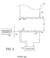
- the wavefront 24 is depolarized relative to the laser beam 18 due to reflection and refraction as the wavefront 24 emanates from the retina 122 . Accordingly, the wavefront 24 is turned at the polarization sensitive beam splitter 20 and directed to a wavefront analyzer 26 such as a Hartmann-Shack (H-S) wavefront analyzer.
- H-S Hartmann-Shack
- the wavefront analyzer 26 measures the slopes of wavefront 24 , i.e., the partial derivatives with respect to x and y, at a number of (x,y) transverse coordinates, as earlier described with reference to FIGS. 1C and 1D. This partial derivative information is then used to reconstruct or approximate the original wavefront with a mathematical expression such as a weighted series of Zemike polynomials.
- the optical train 22 includes a first lens 220, a flat mirror 221 , a Porro mirror 222 and a second lens 224 all of which lie along the path of laser beam 18 and the wavefront 24 .
- the first lens 220 and the second lens 224 are identical lenses maintained in fixed positions.
- the Porro mirror 222 is capable of linear movement as indicated by arrow 223 to change the optical path length between the lenses 220 and 224 .
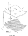
- the dynamic range of the apparatus 10 is further improved by providing an improved wavefront sensor arrangement 28 as illustrated with reference to FIGS. 3 and 4 as disclosed in our International Patent Application No. WO-99/27334.
- each such wavefront portion 25 passes through the hole 34 to illuminate planar array 36 .
- the resulting image formed by each such wavefront portion 25 is a positive shadow of the respective hole 34 .
- diffraction occurs as determined by the diameter D of each hole 34, the wavelength ⁇ of the light source (e.g. the wavefront 24 ) and the separation distance F between the plate 32 and the planar array 36.
- the value of F is varied by the positioning apparatus 42 to adjust the gain based on the particular patient as will be explained further below.
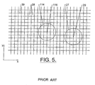
- One method used to determine the centroid 29 of each spot 27 unambiguously with respect to a spot caused by another one of the holes 34 assigns a unique number of cells 38 to each hole 34 .
- the "assigned areas" are designated, as illustrated with reference to FIG. 5, as also described in our International Patent Application No. 99/27334 by way of example, with the heavy grid lines 39 . It is to be understood that the grid lines 39 are not actual physical boundaries between cells 38 but are shown simply to illustrate the unique designated areas containing a plurality of the cells 38 . It is anticipated that other centroid strategies will be utilized that do not necessitate such partitioning of the array 36 given the teachings of the present invention.
- the lenslet array 33 may be operable by the positioning apparatus 42 such that separation distance F is independent of the focal length f that defines the focal plane of the lenslet array 33 which is represented by dashed line 35 .
- the processor 40 computes each two-dimensional centroid 29 of each spot 27 generated by the wavefront 24 .
- the amount of two dimensional centroid shift relative to the centroid of the calibrating spot for each designated area associated with a corresponding hole 34 (or sub-aperture of lenslet array 33 ) is divided by the separation distance F to generate a matrix of local slopes of the wavefront, i.e., ⁇ W(x,y)/ ⁇ x and ⁇ W(x,y)/ ⁇ y at the (x,y) coordinates of the centers of holes 34 .
- ⁇ W(x,y)/ ⁇ x ⁇ W(x,y)/ ⁇ x
- Q(x,y) ⁇ W(x,y)/ ⁇ y, respectively.
- such approaches may include the use of Fourier series and Taylor series.
- the wavefront W(x,y) is expressed as a weighted sum of the individual polynomials where Ci are the weighting coefficients, and Z i (x,y) are the Zernike polynomials up to some order. This is further described in our International Application WO 9927334.
- a method is herein described in accordance with the present invention for identifying individual spots and correlating their geometry.
- the apparatus is configured such that the optical axis is aligned to the center of a particular aperture at the entrance face of the wavefront sensor. This aperture is located at or near the center of the entrance face. If the probe beam entering the eye is also aligned to the system optical axis, then due to the reversible nature of light rays, a light spot will always be seen directly behind the aligned aperture. That is, a spot will always be seen on the CCD sensor at this location, regardless of the wavefront aberrations, and will always correspond to the overlying aperture. Immediately adjacent spots will be minimally displaced from their "zero slope" locations. As one moves further from the central reference spot, generally greater spot displacements will occur. Using this knowledge, it is a relatively straight forward process to identify all the spots in the CCD pattern and establish their geometric relationships.
- the displacement of the centroid from that of a perfectly collimated light beam, corresponding to ideal and emmetropic vision, is then calculated and used to determine the wavefront slope at each sample location.
- the location of the centroids for a collimated light beam may either be directly measured in a calibration step prior to the patient exam, or taken from a calculated reference pattern based on the wavefront sensor construction.
- the apparatus 10 can be augmented by the addition of an eye tracker 25 , illustrated with reference again to FIG. 2.
- an eye tracker 25 illustrated with reference again to FIG. 2.
- One possible placement of the eye tracker 25 is herein illustrated. However, it is to be understood that the eye tracker 25 could be placed elsewhere within the apparatus 10.
- One such eye tracker is disclosed in the aforementioned U.S. Patent No. 5,980,513, commonly owned with the present invention. In this way, wavefront analysis is performed even during a limited amount of eye motion.
- a one-time calibration exposure can also be used to determine the relative sensitivities of the individual cells. This is made in uniform collimated light with plate 32 removed. The responses of individual cells are then recorded. For each light transmissive aperture (e.g, hole 34 ), the centroid in the collimated case serves as a dedicated origin for the particular hole. The shift from the "origin" for each hole to the centroid caused by the wavefront 24 (as observed in this coordinate system) is determined by the direction of the wave surface corresponding to that hole.
- each P(m,n) and Q(m,n) represents the partial derivatives of W(x,y) with respect to x and y for the (x,y) coordinates of each hole 34.
- each hole 34 is assigned its dedicated area of the array 36 or (I m,n ⁇ ⁇ i, j m,n ⁇ ⁇ j). This square of many light-sensitive cells is large enough that neighboring hole images never encroach, and all illumination from this hole is contained. The square contains 4 ⁇ i* ⁇ j cells.
- the functions Z k (x,y) in equation (19) are the Zernike polynomials. There is no standard convention as to their sequence. Thus, for consistency, it is important that the same sequence is used to produce the set C k that was chosen for deriving the matrix TM.
- orders up to and including 4 are used (less Z 0 - the single member of order 0 that is the constant 1 which describes the reference position of the group in the z direction). Since wavefront 24 is moving along z (at the velocity of light), this "piston term" describes only an arbitrary offset in Z, and this term may be ignored.
- the first 5 orders (0, 1, ...,4) contain 15 functions including the piston term.
- 14 values of C k are calculated as coefficients of 14 Zernike polynomials.
- TM one such order used to calculate TM is herein illustrated, and includes both the Zernike functions and their partial derivatives.
- Calculation of the ⁇ z (x,y) optical path difference information from the Zernike reconstruction of the wavefront is accomplished simply by subtracting a constant from the Zemike approximation.
- the value of the constant will depend on the desired characteristics of ⁇ z (x,y).
- transition matrix TM The development of the transition matrix TM will now be explained for the illustrated example of a 7 x 7 array of holes in plate 32.
- the tangents of the components of the normal are P (x i ,y j ) and Q (x i ,y j ) where and Combining these with equation (11), and each applicable to 49 (i,j) combinations.
- PQ that is 98 elements high, i.e., a 98 x 1 matrix.
- Equation (19) can be rewritten as the matrix equation where the top 49 rows of M are the ⁇ W (x i , y j ) / ⁇ y.
- equation (25) gives the normal components in terms of the Zernike coefficients for a surface described by the array of 14 C's. These are exact, but it is not guaranteed that the actual total surface can be described by such an array of coefficients. Accordingly, if it is assumed that the description is within an acceptable tolerance, i.e., tolerating the errors that remain after least square error determination, then equation (26) can be considered to define the column vector C implicitly in terms of the mathematical matrix M and the measured vector PQ, both of which are known.
- the method of effecting the solution under the minimization condition is as follows.
- equation (25) is multiplied on the left by M T , the transpose of M such that where S ⁇ M T M is a square and symmetric matrix, e.g., of dimensions 14 x14 (with each element the sum of 98 products). Such a matrix has an inverse unless the determinant of its coefficients is zero. Since this is based on the Zernike polynomials alone, and they are all independent of each other, the determinant is non-zero, so that an inverse S -1 is defined.
- equation (25) is multiplied on the left by S -1 to yield Then, the mathematical transition matrix (independent of measurement) is and the "best fit" array of C's from the measured PQ's can be produced by the simple matrix multiplication
- a pulsing or shuttering laser source may be used, or an eye tracker.
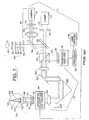
- FIG. 7 An implementation suitable for clinical use is illustrated, by way of example, with reference to FIG. 7 as also described in our International Patent Application No. 99/27334 and is referenced generally by numeral 11 .
- a dichroic beam splitter 52 is interposed between the beam splitter 20 and the optical train 22 to introduce fixation target optics 60 and observation optics 70 into the apparatus 11 which are optically separated from one another by a 50/50 beam splitter 54 .
- Fixation target optics provide the eye 120 with visible light in the shape of a target. The visible light generated by fixation target optics 60 is reflected by the dichroic beam splitter 20 and directed through optical train 22 .
- FIGS. 9-24B and 17A, 27B also referred to in our co-pending European Patent Application No. EP-A-1,153,570
- an exemplary embodiment of the apparatus 10 will be herein described beginning with series 300 , which improved apparatus 300 is constructed as a patient examination station which allows the patient 302 to be comfortably positioned for the measurement of the eye 120 , as earlier described.
- a computer monitor, mouse, and keyboard are located on a separate cart for this embodiment of the present invention, herein described.
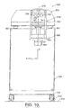
- the apparatus 300 includes a housing 304 having a platform 306 which is carried by a rigid frame 308 .
- the frame 308 includes wheels 310 to facilitate shipping and installation at the clinical site, as well as locking and leveling feet 312 for securing the apparatus to the supporting floor 314 . Once the apparatus is positioned, the integrated leveling feet 312 are deployed to provide a stable stationary frame 308 , and thus platform 306 .
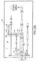
- a fourth optical path 352 a re-emitted wavefront optical path illustrated in isolation in FIG. 12D for convenience to the reader, conveys the reflected wavefront 24 of FIG. 2, and herein described with numeral 354 re-emitted from the eye 120 and directed towards a wavefront sensor 356 .
- first and second afocal relay stages 358, 360 transfer the reflected wavefront 354 from the corneal plane of the eye 120 to the entrance face of the wavefront sensor 356 .
- a fifth optical path 362 a calibration wavefront optical path illustrated in isolation in FIG. 12E for convenience to the reader, injects collimated laser light into the wavefront transfer path leading to the sensor 356 .
- Software operable within the computer 326 described earlier with reference to FIG. 9, uses collimated light wavefront sensor output data to calibrate the apparatus 300 prior to patient measurement.
- the first optical path 340 is herein described as a fixation path which provides a reference image to the patient, such that the eye 120 is properly aligned when the patient is fixating on the reticle 344 of a reference target 366 .
- a target illumination lamp 368 backlights the fixation target 366 , which fixation target image reaches the patient eye 120 by transmission through a 50/50 beam splitter 370, lenses 372, reflection in 50/50 beam splitters 374, 376 , and transmission through lens combinations of afocal relay stage 358 , as well as through polarizing beam splitter 378 .
- a spectral filter is placed over the target illumination lamp 368 to remove radiation over the 620-790 nm wavelength range that might otherwise interfere with a wavefront measurement at 670 nm.
- the lens combinations in the first relay stage 358 contain identical lens elements mounted in reverse order. Each consists of two meniscus lens elements, with an interposed achromatic doublet. The lens combinations work in tandem as a unity magnification afocal relay stage.
- the optical elements including the polarizing beam splitter 378 , the lenses of the first afocal stage 358, the beam splitters 374, 376 , and one lens 380 of the lenses 372 are mechanically fixed in place on the surface of the platform 306 .
- the optical elements including a lens pair 382 of the lenses 372 , the beam splitter 370 , the fixation target 366 , and the illumination lamp 368 are all mounted on one precision linear translation stage, capable of movement along the optical axis 342 of this pathway. Translation of these optical elements focuses the fixation target 366 for the patient's view, compensating for any myopia/hyperopia present in the eye 120 .
- the focus translation stage is adjusted to place the target optically just beyond the eye's infinity focal plane. This allows the patient to see a relatively distinct reticle pattern without stimulating accommodation by the eye 120 .
- the beam splitters 378, 376, 374 serve as interfaces between other optical pathways within the optical axis 342 , as will herein be described in further detail.
- the beam splitter 370 is included for alignment purposes.
- a photo-detector 384 attached to the center of the left edge of beam splitter 370 senses light transmitted toward the fixation target along the optical axis.
- the second optical path 346 captures video images of the eye 120 at an examination plane. This allows the clinical operator/technician to assist in patient alignment, and to measure actual eye displacement during the wavefront measurement.
- the illumination lamps 336 illuminate the eye 120 .
- the image of the eye is conveyed to the video camera 338 by transmission through the polarizing beam splitter 378 and the lens combinations 358, reflection in the 50/50 beam splitter 376, transmission through the 50/50 beam splitter 374, reflection off mirror 386, and transmission through lens 388 . All these optical elements are fixed in place on the surface of the platform 306.
- this second path 346 provides a video field of view approximately 22 mm in diameter at the eye plane, with a limiting resolution of ⁇ 64 mm.
- a number of filters are placed in front of each eye illumination lamp 336 to reduce the spectral bandwidth of the radiation reaching the eye 120 .
- these will includes a blue filter to remove light at wavelengths below ⁇ 455nm (for eye safety), an infrared filter to remove light at wavelengths above ⁇ 920nm (for eye safety), and a rejection filter to remove light over the wavelength range 620nm - 790nm (to prevent interference with the wavefront measurement at 670 nm).
- the third optical path 348 irradiates a small spot on the patient's retina with eye safe laser radiation, as earlier described with reference to FIGS. 1A - 1D.
- the irradiated retinal spot on the fovea centralis 123 of the retina 122 is, as herein described, the origin of the re-emitted wavefront 130 measured by the sensor 356 .
- the output beam, probe laser beam 350 from diode laser 390 reaches the patient eye 120 by transmission through a linear polarizer and attenuator 392 , lens 394 , shutter 396 , and reflection off mirror 398 and in the polarizing beam splitter 378 . All these elements are fixed in position.
- output of the diode laser 390 is essentially collimated and is focused onto a corneal surface of the eye 120 by lens 394 .
- the projected probe laser beam 350 collimated light from the diode laser 390 , is directed by a long focal length lens 394 for focusing on the anterior surface of the cornea 126 of the eye 120 , as illustrated by way of example with reference again to FIG. 1B, passing through the pupil and lens 124 of the eye 120 , and onto the retina 122 as a small measurable spot on the fovea centralis 123.
- the lens 394 comprises a zoom lens for varying the focus and moving the focus location as desired.
- the measurement is minimally dependent on the curvature of the cornea.
- other locations proximate the corneal surface are acceptable.
- the present invention avoids the aberration effects from the cornea which typically dominate.
- the lens of the eye 120 contributes a relatively small aberration effect when compared to that of the cornea 126 .
- selecting a lens with a short focal length would provide a relatively large incident angle of the beam 350, a well focused point on the surface of the cornea 126 , and less aberration effects from the cornea.
- a small incident angle provides a larger focus point on the cornea 126 , but a more desirable smaller spot on the retina 122 , which spot size will depend on the wavelength and starting point size and focal length of the lens 394 selected.
- Embodiments of the present invention including lenses of approximate one half meter and 100 mm, by way of example, haves been effectively used.
- each of the lenses of the second afocal relay stage 360 consists of three lens elements, two meniscus lenses and an interposed achromatic doublet. However, they are not identical, and their combined action serves to magnify the passing wavefront 130.
- the wavefront 354 at the trial lens holder 408 location is imaged onto the surface of the microlens array 412 with a magnification of 1.22. Magnification of the wavefront image by this defined factor of 1.22 reduces the wavefront slope at each point in the image plane by the same 1.22 factor. This extends the measurement dynamic range of the device, again without decreasing accuracy.
- this magnification distributes the wavefront 130 over more elements, CCD cells 38 as earlier described with reference to FIG.
- the microlens array contains a square array of microlenses which divide the incident wavefront into a transverse array of secondary "wavelets.” These wavelets are focused onto a detector surface of the CCD camera, which is positioned parallel to the microlens array and one focal length posterior thereto. The pattern of focused wavelets in the CCD image is used to calculate the shape of the incident wavefront.
- the calibration beam path 362 provides the collimated beam 364 to the Hartman Shack wavefront sensor 356.
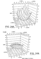
- FIG. 24A An example of the computed Zernike coefficients for an eye and the corresponding wavefront reconstruction 493 is illustrated with reference to FIG. 24A.
- the spherical and cylindrical powers computed from the wavefront are -1.60/-1.13 x 150.4.
- the corresponding values obtained by an optometrist performing a phoropter examination were -1.47/-1.19 x 150.
- the standard measurements of spherical and cylindrical powers agree well with the computation of spherical and cylindrical powers, but there are also higher order aberrations present.
- FIG. 24B illustrates just these higher order aberrations 495 on the same scale as the plot of FIG. 24A.
- OPD optical path difference
- scaling an optical path difference profile, OPD(x,y), by a refractive index difference (cornea to air) is not the only step included to calculate the correct ablation profile.
- the present invention allows for a treatment on the curved corneal surface, while the wavefront measurement was made at a plane tangent to the cornea, as illustrated with reference to FIG. 25, which is exaggerated to illustrate the effect.
- the image plane of the wavefront path is the lenslet array plate.
- the object plane of the wavefront path is the reference plane 494 .
- one light ray 496 emerging from the eye 120 at transverse location a is detected at a transverse location b.
- the wavefront reconstructed from sensor data will have the slope of this ray at location b .
- This is true of the wavefront at the reference plane 494 simple scaling of this wavefront would yield an ablative treatment at corneal location b that may not be entirely correct. In actuality this effect is small.
- the radius of curvature of the cornea is typically on the order of 7.5 mm. (a range of 7-8 mm encompasses most eyes.)
- compensating for the curved geometry may be performed in the following manner:
- a wavefront measurement has the patient correctly positioned at the apparatus 300 .
- the eye 120 being measured is at the correct location and looking in the appropriate direction.
- the apparatus 300 of this embodiment of the present invention provides the following patient position information:
- This embodiment of the apparatus includes a sufficient dynamic range to measure eyes over the expected scope of refractive errors.
- the apparatus detects complex aberrations, and does so with sufficient accuracy to serve as the basis for ablative treatment.
- a computation of a shot pattern is performed in the LADARVision® system.
- the Zernike coefficients computed in the manner described here are imported into the LADARVision® system along with all other d measurement and patient information and used along with LADARVision® system parameters to compute the optimal number and placement of shots.
- One embodiment of the present invention for a calculation of a treatment laser spot pattern includes an ablation effectiveness distribution over the corneal surface.
- One embodiment of the present invention optimizes refractive surgery ablation profiles so that post operative aberrations are minimized.
- One treatment profile takes into account information beyond just that of pre-operative aberrations.
- wave front measurement devices has provided greater insight into the effectiveness of current excimer ablation profiles.
- Analysis of multiple patients for pre and post laser reflective surgery has resulted in a model for describing an effectiveness of a laser ablation as a radially symmetric attenuation function.
- One embodiment of the present venture provides for this attenuation function. As illustrated by way of example with reference to FIGS.
- FIG. 26A illustrates an intended and achieved profile for surgery on a myopic eye
- the 26B illustrates an intended and achieved profile for surgery on a hyperopic eye.
- the ablation depth versus normalized radial profile plots of FIGS. 26A and 26B are representative of multiple surgeries analyzed.
- a constant attenuation independent of radial position results. Sometimes the attenuation is zero.
- a radially symmetric attenuation function results.
- the attenuation function may be graphically described, by way of example, with reference to FIG. 26C.
- an embodiment of the present invention takes a previously unknown efficiency or attenuation function and modifies treatment profiles accordingly so that a desired outcome is achieved. By way of illustration and example, this may be accomplished by taking a desired change in corneal depth (e.g. a nominal ablation profile), and dividing the nominal profile by the attenuation function.
- P INPUT P DESIRED ⁇ A ⁇ 1+B ⁇ 2 +C ⁇ 4 ⁇
- the output from wavefront analyzer 26 can be used in a variety of ways.
- the output may be used to continually or periodically monitor the progress or effects of an ophthalmic procedure, with such stored on disc or transmitted via e-mail, and the like.
- the measurement of the eye and the resulting surgery need not take place at the same site.
- the output could also be used to develop an optical correction for the eye 120 .
- the optical correction will make the aberrated wavefront 130 appear approximately as the planar wavefront 110 .
- the optical correction can be implemented in a variety of ways.
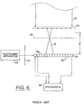
- the output of the wavefront analyzer 26 is input to a processor 90 which converts the Zemike expansion of equation (19) into a form suitable for being implemented as one of the possible optical corrections.
- the processor 90 may also be implemented at the processor 40 of the wavefront analyzer 26 , described earlier with reference to FIG. 6.
- the processor 90 can be used with preselected Zernike coefficients from the expansion of equation (19) to generate a standard sphero-cylindrical correction for a lens grinder 92 to produce a conventional optical lens, e.g., a lens for glasses, a contact lens, and the like.
- the processor 90 includes a modification of the Zernike reconstruction of the aberrated wavefront 130 by the index of refraction of the cornea 126 minus that of air, having value of 1 , as earlier described, to calculate an amount of corneal material to be ablated at each corresponding (x,y) location on the cornea 126 .
- This information regarding the amount of corneal material can be used in conjunction with a laser beam delivery system 94 that typically has eye tracking capability.
- the laser beam delivery system 94 including the eye tracker is placed in line with the optical axis of the apparatus 11 , as illustrated again with reference to FIG. 7.
- the eye tracker portion allows the apparatus 11 to respond to unwanted eye motion.
- the system 94 would typically focus short pulses or "shots" of ablating laser light onto the cornea 126 to remove a specified thickness t of material at each location.
- the ablation thickness t is specified across the aperture of the cornea measured, e.g., the 6 millimeter circle to which the eye's pupil was dilated during the measurement of the eye. Outside the prescribed treatment circle, a tapering blend zone of partial ablation may be added to minimize severe changes in corneal curvature and hence lessen regression.
- the laser beam delivery system 94 removes thickness t to achieve the optical correction, which results in the corrected cornea surface 126B .
- the optical correction is not concerned with the ultimate corneal topography, but instead removes corneal material to achieve an optical correction that takes into account all ocular aberrations of the eye 120 .
- This is important because the shape of the corneal surface can be independent of the correction d because the eye's vision depends on numerous factors besides corneal curvature.
- the best corneal surface topography for optimal vision may be far from regular in that it may compensate for the errors in the eye's other surfaces.
- the present invention can be used to provide corneal surface corrections other than the conventional spherical and/or cylindrical corrections.
- the apparatus 300 of the present venture includes first and second afocal relays stages 358, 360 .
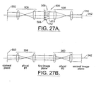
- first and second afocal relays stages 358, 360 To retain the benefit of wavefront magnification, as a means of increasing the dynamic range of the wavefront sensor 356 to accommodate patients with large refractive errors, while at the same time allowing for incorporation of a small format, inexpensive camera to record the wavefront slope data, a modification 500 to the apparatus 300 as illustrated with reference to FIG. 27A is provided.
- a lens array may also be positioned and configured as illustrated with reference to FIG. 27B, wherein a portion of the apparatus 300 of FIG. 12 includes the first and second afocal stages 358, 360 within the optical axis 342 , and the wavefront sensor 356 consist of the microlens array and CCD camera separated by a fixed distant, as earlier described with reference to FIG. 6.
- This optical path through the afocal relay stages results in an image of the corneal plane 502 at the lenslet array, i.e. at the entrance face of the actual wave front sensor 356 . This can be accomplished by a single afocal stage.
- FIG. 27B a portion of the apparatus 300 of FIG. 12 includes the first and second afocal stages 358, 360 within the optical axis 342 , and the wavefront sensor 356 consist of the microlens array and CCD camera separated by a fixed distant, as earlier described with reference to FIG. 6.
- This optical path through the afocal relay stages results in an image
- the apparatus 300 includes an intermediate image plane as insertion point, the holder 408 , for a trial lens. Placing a spherical lens into the optical axis 342 at the first image plane, in theory, could be used to remove the defocus wavefront error. This would potentially expand the dynamic range of the apparatus 300 .
- the trial lens approach s a moving mechanism that can position lenses at the first image plane with tremendous accuracy in repeatability. It is highly desirable that alternative means be developed to address dynamic range.
- One way to accomplish this is to magnify the corneal plane image at the lenslet array with the afocal stage 360 , earlier described. Magnification of the wavefront reduces the wavefront slope, so that the displacement of the focused lights spots on the CCD is decreased.
- the chosen magnification factor used with the apparatus 300 second afocal stage 360 is approximately 1.2 which is sufficient to cover the desired range in refractive errors. A magnification factor in excess of 1.5 is desirable for expanding the use of the apparatus 300.
- simply magnifying the corneal plane has a drawback in that it necessitate a large aperture wavefront sensor. That is, both the lens array and the CCD camera preferably have large cross-sectional areas to encompass the magnified image of the point of plane. This is not a significant issue for the lens array.
- a large format CCD camera is quite expensive and such cameras are only available from a limited number of vendors.
- the corneal plane 502 is imaged at a reference plane 504 by an afocal relay stage 506 , which magnifies the corneal plane by a preselected amount.
- the lenslet array 412 is placed at the reference plane 504. Focused spots of light from the eye 120 are produced at the lenslet array focal plane 504 .
- an optical train 508 is inserted to image the array focal plane 413 at yet another plane, a final image plane 510 , at which plane the CCD detector face is positioned.
- magnification of the array focal plane at the final image plane 510 is provided. This allows a small, relatively inexpensive, active area camera to be used as the light recording element in the wavefront sensor. Details of optical design including magnification specifics can be adjusted to maximize performance for a given camera and lens array plate specification.
- the advantages of the present invention are numerous. A totally objective approach is presented for measuring ocular aberrations. The approach is effective for a wide range of vision defects. Accordingly, the present invention will be of great utility in a wide variety of clinical applications.
- the calculated Zernike coefficients can be used to develop a completely objective lens prescription or a corneal correction that could be accomplished with laser ablation.
- each of the wavefront sensor embodiments provides for a greater degree of accuracy over the prior art with respect to measuring wavefront deflections. Further, the present wavefront sensor can be adjusted in terms of gain simply by adjusting the separation distance between the imaging plane of the sensor and the planar array of light-sensitive cells.
- the objective measurement of the present invention will also find great utility for a large variety of applications where the "patient” is unable to provide feedback as d by conventional eye diagnosis.
- the present invention could be used to evaluate the eyes of any patient not possessed of demonstrative communicative skills, e.g., babies, animals, dead specimens, as well as any constructed optical system, since the present invention is an objective analysis not requiring any assessment from the "subject". All that is necessary is for the subject's eye to be properly positioned so that proper optical access to the eye can be obtained.
- the present invention will also be used in the area of identification should it be determined that each eye's Zemike coefficients are unique. Then, the present invention would find great utility in the fields of law enforcement, credit card/bank security, or any other field where positive identification would be beneficial.
Abstract
Description
- The invention relates generally to optical aberration measurement and correction, and more particularly to an objective measurement and correction of optical systems, such as systems of a human eye.
- Optical systems having a real image focus can receive collimated light and focus it at a point. Such optical systems can be found in nature, e.g., human and animal eyes, or can be man-made, e.g., laboratory systems, guidance systems, and the like. In either case, aberrations in the optical system can affect the system's performance. By way of example, the human eye will be used to explain this problem.
- A perfect or ideal eye diffusely reflects an impinging light beam from its retina through optics of the eye which includes a lens and a cornea. For such an ideal eye in a relaxed state, i.e., not accommodating to provide near-field focus, reflected light exits the eye as a sequence of plane waves. However, an eye typically has aberrations that cause deformation or distortion of reflected light waves exiting the eye. An aberrated eye diffusely reflects an impinging light beam from its retina through its lens and cornea as a sequence of distorted wavefronts.
- There are a number of technologies that attempt to provide the patient with improved visual acuity. Examples of such technologies include remodeling of the cornea using refractive laser surgery or intra-corneal implants, adding synthetic lenses to the optical system using intra-ocular lens implants, and precision-ground spectacles. In each case, the amount of corrective treatment is typically determined by placing spherical and/or cylindrical lenses of known refractive power at the spectacle plane (approximately 1.0-1.5 centimeters anterior to cornea) and literally asking the patient which lens or lens combination provides the clearest vision. This is an imprecise measurement of true distortions in the reflected wavefront because 1) a single spherocylindrical compensation is applied across the entire wavefront, 2) vision is tested at discrete intervals (i.e., diopter units) of refractive correction, and 3) subjective determination by the patient is desired in order to determine the optical correction. Thus, conventional methodology for determining refractive errors in the eye is substantially less accurate than the techniques now available for correcting the ocular aberrations.
- One method of measuring ocular refractive errors is disclosed in U.S. Patent No. 5,258,791 to Penney et al. for "Spatially Resolved Objective Autorefractometer," which teaches the use of an autorefractometer to measure the refraction of the eye at numerous discrete locations across the corneal surface. The autorefractometer is designed to deliver a narrow beam of optical radiation to the surface of the eye, and to determine where that beam strikes the retina using a retinal imaging system. Both the angle of the beam's propagation direction with respect to the optical axis of the system and the approximate location at which the beam strikes the corneal surface of the eye are independently adjustable. However, a small uncertainty or error in the location of the beam's point of incidence on the cornea exists due to the curved corneal surface. For each point of incidence across the corneal surface, the refraction of the eye corresponding to that surface point can be determined by adjusting the angle at which the beam strikes the cornea until the beam refracted on to the iris strikes the fovea centralis. Adjustment of the beam angle of propagation can be accomplished either manually by the patient or automatically by the autorefractometer, if a feedback loop involving a retinal imaging component is incorporated.
- Penney '791 further teaches the use of the autorefractometer measurements in determining the appropriate corneal surface reshaping to provide emmetropia, a condition of a normal eye when parallel beams or rays of light are focused exactly on the retina and vision is perfect. This is accomplished by first obtaining an accurate measurement of corneal surface topography using a separate commercially available device. A mathematical analysis is then performed using an initial corneal topography at each surface reference point, the measured refraction at each surface point, and Snell's law of refraction, to determine a desired change in surface contour at each reference point. The contour changes at the various reference points are then combined to arrive at a single reshaping profile to be applied across the full corneal surface.
- A major limitation to the approach described by Penney '791 is that a separate measurement of corneal topography is desired to perform the Snell's Law analysis of needed refraction change. This adds significantly to the time and cost of a complete and desirable diagnostic evaluation. Further, the accuracy of the refraction change analysis will be dependent upon the accuracy of the topographic measurement and the accuracy of the autorefractometer measurement. In addition, any error in the spatial orientation of a topography map with respect to a refraction map will degrade the accuracy of the needed correction profile. Yet another limitation to known approaches such as described in Penney '791, by way of example, is that test points on the corneal surface are examined sequentially. Eye motion during the examination, either voluntary or involuntary, could introduce substantial errors in the refraction measurement. Penney '791 teaches detection of such eye movement by deliberately including measurement points outside the pupil, i.e., in the corneal region overlying the iris, where the return from the retina will obviously be zero at specific intervals in the examination sequence. However, this approach may still allow substantial undetected eye movement error between such iris reference points.
- By way of example, one method and system known in the art, are disclosed by Junzhong Liang et al. in "Objective Measurement Of Wave Aberrations Of The Human Eye With The Use Of A Hartmann-Shack Wave-Front Sensor," published in the Journal of the Optical Society of America,
Volume 11, No. 7, July 1994, pages 1949-1957. Liang et al. teach the use of a Hartmann-Shack wavefront sensor to measure ocular aberrations by measuring the wavefront emerging from the eye by the retinal reflection of a focused laser light spot on the retina's fovea. The actual wavefront is reconstructed using wavefront-estimation with Zernike polynomials. - The imprecise measurement technique of placing lenses of known refractive power anterior to the comea and asking a patient which lens or lens combination provides the clearest vision has been improved with the use of autorefractometers, as described in Penny '79, or with the use of wavefront sensors as described by Liang et al. Spatially resolved refraction data, in combination with measured existing surface contour of the anterior surface of the eye, enable a calculation of a detailed spatially resolved new contour which provides corrected vision. However, it would be an improvement in this art if such vision correction could be made without the need for this contour data, and further without the need for feedback from the patient regarding an appropriate lens. Liang et al. discloses the use of a Hartmann-Shack wavefront sensor to measure ocular aberrations by measuring the wavefront emerging from the eye by retinal reflection of a focused laser light spot on the retina's fovea. A parallel beam of laser light passes through beam splitters and a lens pair which brings the beam to a focus point on the retina by the optics of the eye. Possible myopia or hyperopia of the tested eye is corrected by movement of a lens within the lens pair. The focused light on the fovea is then assumed to be diffusely reflected and acts as a point source located on the retina. The reflected light passes through the eye and forms a distorted wavefront in front of the eye that results from the ocular aberrations. The aberrated wavefront is then directed to the wavefront sensor.
- A point source of radiation on the retina would be ideal for such measurements. However, when the perfect eye receives a collimated beam of light, the best possible image on the retina is a diffraction limited spot. As illustrated by way of example, with Penny et al. and Liang et al., discussed above, and typical for those of skill in the art, parallel or collimated beams are used with the optics of the eye being measured to achieve this diffraction limited spot for such objective measurements. To do so, a setup for each patient includes a corrective lens or lens combination and adjustments thereto for accommodating that patient's specific visual acuity. Providing a corrective or lens combination, as well as setting up for their use becomes cumbersome, time consuming, and at an additional expense. Eliminating the need for such corrective optics is desirable and eliminates a variable within optical measurement systems that typically include many variables. Further, there is a need for providing optical characteristics of an eye without requiring feedback from the patient. By way of example, the patient may be a wild or domestic animal, living or dead.
- The Hartmann-Shack wavefront sensor disclosed by Liang et al. includes two identical layers of cylindrical lenses with the layers arranged so that lenses in each layer are perpendicular to one another, as further disclosed in U.S. Patent No. 5,062,702 to Bille. In this way, the two layers operate as a two-dimensional array of spherical lenslets that divide the incoming light wave into sub-apertures. The light through each sub-aperture is brought to focus in the focal plane of the lens array where a charge coupled device (CCD) image module resides.
- The system of Liang et al. is calibrated by impinging an ideal plane wave of light on the lenslet array so that a reference or calibrating pattern of focus spots is imaged on the CCD. Since the ideal wavefront is planar, each spot related to the ideal wavefront is located on the optical axis of the corresponding lenslet. When a distorted wavefront passes through the lenslet array, the image spots on the CCD are shifted with respect to a reference pattern generated by the ideal wavefront. Each shift is proportional a local slope, i.e., partial derivatives of the distorted wavefront, which partial derivatives are used to reconstruct the distorted wavefront, by means of modal wavefront estimation using Zernike polynomials.
- However, the system disclosed by Liang et al. is effective only for eyes having fairly good vision. Eyes that exhibit considerable myopia (nearsightedness) would cause the focus spots to overlap on the CCD, thereby making local slope determination practically impossible for eyes having this condition. Similarly, eyes that exhibit considerable hyperopia (farsightedness) deflect the focus spots such that they do not impinge on the CCD thereby again making local slope determination practically impossible for eyes having this condition.
- The present invention relates to an optical correction system as defined in
claim 1. - Preferred embodiments are detailed in the dependent claims.
-
- FIG. 1A is a schematic view of the ideal eye reflecting light from its retina as a planar wavefront;
- FIG. 1B is a schematic view of an aberrated eye reflecting light from its retina as a deformed wavefront;
- FIG. 1C is a schematic view of the distorted wavefront relative to a reference plane to show the wavefront error or optical path difference as a function of transverse distance in the propagation direction;
- FIG. 1D is a schematic view illustrating use of a reference plane;
- FIG. 2 is a simplified schematic of the system for determining ocular aberrations in accordance with the essential features of the present invention;
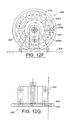
- FIG. 3 is a schematic of a Hartmann-Shack wavefront analyzer;
- FIG. 4 is a perspective view of a portion of the pinhole imaging plate and planar array of light-sensitive cells comprising the wavefront sensor from FIG. 3 where the deflection of a wavefront piece associated with an aberrated eye is shown in comparison with a wavefront piece associated with a calibration or planar wavefront;
- FIG. 5 is a plan view of a designated area on the planar array of light-sensitive cells associated with a corresponding hole;
- FIG. 6 is a schematic of another wavefront analyzer;
- FIG. 7 is a schematic view of a prior art arrangement suitable for ophthalmic use;
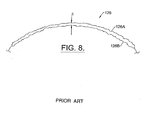
- FIG. 8 is a side view of a cornea showing a thickness of corneal material to be ablated as an optical correction;
- FIG. 9 is a side elevation view of one embodiment of the present invention illustrating a patient positioning for measurement;
- FIG. 10 is an end elevation view of the embodiment of FIG. 9;
- FIG. 11 is an enlarged perspective view of an patient positioning portion of the embodiment of FIG. 9;
- FIG. 12 is a top plan view of optical elements of the embodiment of FIG. 9;
- FIG. 12A illustrates a fixation target optical path of FIG. 12;
- FIG. 12B illustrates a video image optical path of FIG. 12;
- FIG. 12C illustrates a probe laser optical path of FIG. 12;
- FIG. 12D illustrates a re-emitted wavefront optical path of FIG. 12;
- FIG. 12E illustrates a calibration wavefront optical path of FIG. 12;
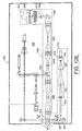
- FIGS. 12F and 12G are front elevation and top plan views of a trial lens holder useful with embodiments of the present invention herein described;
- FIG. 13 is a block diagram illustrating electrical components of the embodiment of FIG. 9;
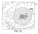
- FIG. 14 is an enlarged image of an eye illustrating a centration image;
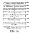
- FIG. 15 is a block diagram illustrating an operable flow of steps used in one embodiment of the present invention;
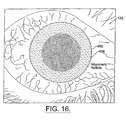
- FIG. 16 is an enlarged image of an eye illustrating a pre-measurement eye alignment;
- FIG. 17 is an enlarged image of an eye illustrating a pre-measurement eye alignment checking thereof;
- FIG. 18 is a line diagram illustrating an eye registration pattern;
- FIG. 19 illustrates a rejected CCD image;
- FIG. 20 illustrates a CCD image including centroids;
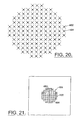
- FIG. 21 is an enlarged image of a centroid;
- FIG. 22 illustrates an image available to an operator of a measured and reference centroid;
- FIG. 23A illustrates a spacial filter operable in one embodiment of the present invention;
- FIG. 23B illustrates a noisy CCD image before filtering to provide an image as illustrated with reference to FIG. 20;
- FIG. 24A is a three dimensional plot of a wavefront reconstruction in accordance with the present invention;
- FIG. 24B illustrates a higher order aberration for the wavefront of FIG. 23;
- FIG. 25 illustrates a geometric effect of a curved corneal surface on a wavefront measurement in accordance with the present invention;
- FIGS. 26A and 26B illustrate ablation depth profiles for surgery on a myopic eye and a hyperopic eye, respectively, in accordance with the present invention;
- FIG. 26C illustrates an ablation efficiency function for one embodiment of the present invention;
- FIG. 27A is a pictorial line drawing illustrating magnification modification to the embodiment of FIG. 12; and
- FIG. 27B is a pictorial line drawing illustrating optical elements of the present invention.
-
- The present invention will now be described more fully hereinafter with reference to the accompanying drawings, in which prior art examples and embodiments of the present invention are shown by way of illustration and example. This invention may, however, be embodied in many forms and should not be construed as limited to the embodiments set forth herein. Rather, these embodiments are provided so that this disclosure will be thorough and complete, and will fully convey the scope of the invention to those skilled in the art. Like numbers refer to like elements throughout.
- By way of illustrative example, the present invention will be described with respect to diagnosing and correcting a human eye. However, it is to be understood that the teachings of the present invention are applicable to any optical system having a real image focus that can be, or can be adapted to diffusely reflect a focused spot of radiation from a rear portion of the optical system back through the optical system as a wavefront of radiation. Thus, the present invention can be used with human or animal eyes of patients that may be alive or dead, or any man-made optical system.
- Correction of the human eye that may be used in conjunction with or based upon the diagnostic information provided by embodiments of the present invention include, by way of example, the grinding or preparation of eye glasses and lenses, which teachings are well known in the art, such as described in "Geometric, Physical, and Visual Optics" by Michael P. Keating, Ph.D. published by Butterworth Publishers, 80 Montvale Avenue, Stone, MA 02180, Copyright 1988. Laser surgery using lasers that photo ablate corneal tissue through the use of broad beam excimer lasers which are well known in the art, such as those disclosed in U.S. Patent No. 5,163,934 to Trokel, correction of presbyopia by photorefractive keratectomy disclosed in U.S. Patent No. 5,395,356 to King et al., and narrow beam systems as described in U.S. Patent No. 5,849,006 to Frey et al. in conjunction with a Lasik procedure which are well known in the art.
- The method of using wavefront analysis to determine an appropriate optical correction will be introduced with reference to the eye example and the aid of the schematic drawings of FIGS. 1A, 1B, and 1C as disclosed in our International Patent Application No. WO-99/27334. As earlier described with reference to an ideal eye, and with reference now to FIG. 1A, the ideal emmetropic or
perfect eye 100 diffusely reflects an impinging light beam (not shown for sake of clarity) from the back of its retina 102 (i.e., the fovea centralis 103) through the eye's optics which includeslens 104 andcornea 106. For such anideal eye 100 in a relaxed state, i.e., not accommodating to provide near-field focus, the reflected light (represented by arrows 108) exits theeye 100 as a sequence of plane waves, one of which is represented bystraight line 110. However, as illustrated with reference to FIG. 1B, atypical eye 120 normally has aberrations that cause deformation or distortion of a reflected wave exiting the eye, where theaberrated eye 120 diffusely reflects an impinging light beam (again not shown for sake of clarity) from the back of itsretina 122 of thefovea centralis 123 throughlens 124 andcornea 126. For theaberrated eye 120, the reflected light 128 exits theeye 120 as a sequence of distorted wavefronts, one of which is represented bywavy line 130. - With reference now to FIG. 1C, a coordinate system is defined for convenience, where positive x is upward in the plane of the figure, positive y is outward from the plane of the figure, and positive z is to the right along a propagation direction. The distorted
wavefront 130 is herein described mathematically as W(x,y). One method of measuring distortions in thewavefront 130 is by determining a spatial separation Δz between a reference plane 131 (by way of example, a plane analogous to the ideal wavefront 110) at a known distance Z0 from theeye 120 at each (x,y) point of the distortedwavefront 130 as the leading edge of thewavefront 130 traverses the distance Z0. This is described mathematically as:eye 120 being tested, by way of example. An appropriate correction consists of removing these optical path differences. By way of example, such correction is performed atreference plane 131. - Depending on the desired corrective therapy (corneal tissue ablation, synthetic lens addition, by way of example), the amount of material removed or added at each (x, y) coordinate can be calculated directly if the refractive index of the material in question is known. For many procedures, such as intra-ocular lens implantation or radial keratotomy, a wavefront analysis may be performed repetitively during a procedure to provide feedback information as to the appropriate endpoint of the procedure.
- In terms of the illustrative example, the differences Δz(x,y) between the
distorted wavefront 130 and theideal wavefront 110 are the consequence of the aberrations in the eye. Correction of these aberrations consists of introducing an optical path difference at thereference plane 131 of negative Δz(x,y). If the treatment approach, by way of example, consists of removing tissue from the surface of thecornea 126 by laser ablation, then one choice for the location ofreference plane 131 is tangential to the surface of cornea 126 (i.e. at z=O). This is illustrated schematically with reference to FIG. 1D as disclosed in our International Patent Application No. WO-99/27334, where the curvature of thecornea 126 is greatly exaggerated for clarity of illustration. Ablation is then carried out discretely at each (x,y) coordinate along thecornea 126 by a laser beam delivery and eye tracking system such as described in U.S. Patent Nos. 5,980,513; 5,849,006; and 5,632,742, commonly owned with the present invention. - The appropriate corneal ablation depth at any (x,y) transverse coordinate is, to within a small error, given by:
wavefront 130, i.e. ∂W(x,y)/∂x and ∂W(x,y)/∂y, at a number of points in the transverse x and y directions inreference plane 131 and then generating a mathematical description of W(x,y) having slopes in best possible agreement with the experimentally determined values. One such slope ∂W(x, y) /∂x is illustrated with reference again to FIG. 1D. In doing this, a small error is introduced due to the fact that distortedwavefront 130 is measured at thereference plane 131 whilewavefront 130 emerged from a curved corneal surface just posterior to referenceplane 131. By way of example, an error Ex(x,y) is the lateral displacement in the x-direction at each (x,y) location at the measurement plane (i.e., reference plane 131) to the curved corneal surface. A similar error will be manifest for any corrections involving curved optical surfaces. The error will generally increase with both (x,y) displacement from the point of tangency and local wavefront error. - For refractive surgery, the error may be negligibly small. The magnitude of error Ex(x,y) can be found for each measurement location (x,y) measured at an arbitrary coordinate, e.g., (x0,y0) by projecting that location back to the point of origin on the
cornea 126. This is explained mathematically with reference again to FIG. 1D, where by way of example, it is assumed that the error is in the plane of the figure, i.e., the plane defined by y=y0, although it is quite straightforward mathematically to extend the analysis to include errors in the y-dimension. The quantification of a line L tracing the propagation of thewavefront 130 measured at (x0,y0) in the z0 reference plane from the corneal surface to the reference plane is:If the corneal surface in the plane of the figure is described by the expression S(x0,y0), then the point of origin for the
wavefront 130 in question can be found by finding the point of intersection between L(x) and S (x, y0). Mathematically, one finds the value x', that satisfies L(x') = S(x0,y0). The error Ex(x0,y0) is then given as EX(X0,Y0)=X'-X0. Extending the analysis to consider errors in the y-direction would yield a similar expression for Ey where Ey(X0, y0)=y'-y0. If significant, these transverse errors can be compensated for by laterally displacing the aberration correction calculated at each (x,y) coordinate by the amounts Ex(x,y) and Ey(x,y). - In the case of human corneas, the transverse error under most circumstances will be negligible. The error will be zero at the origin where the corneal tissue and
reference plane 131 are tangent. For human corneas, the tissue is approximately spherical with a radius of curvature of approximately 7.5-8.0 mm. The corrective treatment radius is typically no more than 3 mm, and local wavefront radius of curvature will almost never exceed 50 mm (a 20 diopter refractive error). The transverse error E at a 3 mm treatment radius for a local wavefront radius of curvature of 50 mm is less than 40 µm. - In order to perform wavefront analysis in a manner compatible with corrective procedures such as those described above, the amount of spatial separation of component portions of
wavefront 130 relative to the corresponding component portions of the planar orideal wavefront 110 is measured. It is the system and method of the present invention that allows such separation to be objectively and accurately measured for even substantiallyaberrated eyes 120 including those exhibiting severe defects such as severe myopia or hyperopia. - For the evaluation or measurement portion of the present invention, the patient's pupil should ideally be dilated to approximately 6 mm or more, i.e., the typical size of a human pupil in low light. Smaller amounts of dilation or no dilation at all may also evaluated or measured. In this way, the eye is evaluated while it is using the greatest area of the cornea so that any correction developed from such measurement takes into account the largest usable corneal area of the patient's eye. A lesser amount of the cornea is used in daylight where the pupil is considerable smaller, e.g., on the order of 3 millimeters. Dilation can be brought about naturally by implementing the measurement portion of the present invention in a low light environment such as a dimly lit room. Dilation can also be induced through the use of pharmacologic agents.
- Referring now to FIG. 2 as disclosed in our International Patent Application No. WO-99/27334 a simplified schematic of one exemplary embodiment of the
apparatus 10 is illustrated. Theapparatus 10 includes alaser 12 for generating optical radiation used to produce a small-diameter laser beam 14. Thelaser 12 generates a collimated laser light beam (represented by dashed lines for the beam 14) of a wavelength and power that is eye-safe. For ophthalmic applications, appropriate wavelengths would include the entire visible spectrum and the near infrared spectrum. - To select a small-diameter collimated core of
laser light beam 14, aniris diaphragm 16 is used to block all oflaser light beam 14 except for thelaser beam 18 of a size desired for use. Thelaser beam 18 will have a diameter in the range of approximately 0.5-4.5 millimeters with 1-3 millimeters being typical, by way of example. A badly aberrated eye uses a smaller diameter beam while an eye with only slight aberrations can be evaluated with a larger diameter beam. Depending on the output divergence of thelaser 12, a lens, as will be later described, can be positioned in the beam path to optimize collimating of the beam. -
Laser beam 18, as herein described by way of example, is a polarized beam that is passed through a polarizationsensitive beam splitter 20 for routing to a focusingoptical train 22 which optical train operates to focus thelaser beam 18 through the optics of the eye 120 (e.g., thecornea 126,pupil 125 and the lens 124) to theretina 122. It is to be understood that thelens 124 may not be present for a patient that has undergone a cataract procedure. In the illustrated example of FIG. 2, theoptical train 22 images thelaser beam 18 as a small spot of light at or near the eye'sfovea centralis 123 where the eye's vision is most acute. Note that the small spot of light could be reflected off another portion ofretina 122 in order to determine aberrations related to another aspect of one's vision. - The diffuse reflection of the
laser beam 18 back from theretina 122 is represented in FIG. 2 bysolid lines 24 indicative of radiation that passes back through theeye 120. Thewavefront 24, earlier described with reference to FIG. 1B as distortedwavefront 130 impinges on and is passed through theoptical train 22 and on to the polarizationsensitive beam splitter 20. Thewavefront 24 is depolarized relative to thelaser beam 18 due to reflection and refraction as thewavefront 24 emanates from theretina 122. Accordingly, thewavefront 24 is turned at the polarizationsensitive beam splitter 20 and directed to awavefront analyzer 26 such as a Hartmann-Shack (H-S) wavefront analyzer. In general, thewavefront analyzer 26 measures the slopes ofwavefront 24, i.e., the partial derivatives with respect to x and y, at a number of (x,y) transverse coordinates, as earlier described with reference to FIGS. 1C and 1D. This partial derivative information is then used to reconstruct or approximate the original wavefront with a mathematical expression such as a weighted series of Zemike polynomials. - Dynamic range enhancement is accomplished with the
optical train 22 and/or a wavefront sensor portion of thewavefront analyzer 26. With continued reference to FIG. 2, theoptical train 22 includes afirst lens 220, aflat mirror 221, aPorro mirror 222 and asecond lens 224 all of which lie along the path oflaser beam 18 and thewavefront 24. Thefirst lens 220 and thesecond lens 224 are identical lenses maintained in fixed positions. ThePorro mirror 222 is capable of linear movement as indicated byarrow 223 to change the optical path length between thelenses - The dynamic range of the
apparatus 10 is further improved by providing an improvedwavefront sensor arrangement 28 as illustrated with reference to FIGS. 3 and 4 as disclosed in our International Patent Application No. WO-99/27334. - As illustrated with reference to FIG. 4 as disclosed in our International Patent Application No. WO-99/27334 when the
wavefront 24 impinges on theplate 32, a portion of thewavefront 24, indicated byarrow 25, passes through thehole 34 to illuminateplanar array 36. To a first order, the resulting image formed by eachsuch wavefront portion 25 is a positive shadow of therespective hole 34. However, diffraction occurs as determined by the diameter D of eachhole 34, the wavelength λ of the light source (e.g. the wavefront 24) and the separation distance F between theplate 32 and theplanar array 36. The value of F is varied by thepositioning apparatus 42 to adjust the gain based on the particular patient as will be explained further below. - One method used to determine the
centroid 29 of eachspot 27 unambiguously with respect to a spot caused by another one of theholes 34, assigns a unique number ofcells 38 to eachhole 34. The "assigned areas" are designated, as illustrated with reference to FIG. 5, as also described in our International Patent Application No. 99/27334 by way of example, with the heavy grid lines 39. It is to be understood that thegrid lines 39 are not actual physical boundaries betweencells 38 but are shown simply to illustrate the unique designated areas containing a plurality of thecells 38. It is anticipated that other centroid strategies will be utilized that do not necessitate such partitioning of thearray 36 given the teachings of the present invention. - By way of example, a wavefront analyzer that replaces
plate 32 described with reference to FIG. 3, with a two dimensional array of identicalspherical lenslets 33, could be used, as illustrated with reference to FIG. 6 as also described in our International Patent Application No. 99/27334 in such an arrangement, thelenslet array 33 may be operable by thepositioning apparatus 42 such that separation distance F is independent of the focal length f that defines the focal plane of thelenslet array 33 which is represented by dashedline 35. - Regardless of the structure of the wavefront sensor, the
processor 40 computes each two-dimensional centroid 29 of eachspot 27 generated by thewavefront 24. The amount of two dimensional centroid shift relative to the centroid of the calibrating spot for each designated area associated with a corresponding hole 34 (or sub-aperture of lenslet array 33) is divided by the separation distance F to generate a matrix of local slopes of the wavefront, i.e., ∂W(x,y)/∂x and ∂W(x,y)/∂y at the (x,y) coordinates of the centers ofholes 34. For simplicity of discussion, these will be indicated by P(x,y)=∂W(x,y)/∂x and Q(x,y)=∂W(x,y)/∂y, respectively. - Numerous methods exist for using the partial derivative data to calculate the distorted
wavefront 
- Briefly, the wavefront W(x,y) is expressed as a weighted sum of the individual polynomials where Ci are the weighting coefficients, and Zi(x,y) are the Zernike polynomials up to some order. This is further described in our International Application WO 9927334.
- A method is herein described in accordance with the present invention for identifying individual spots and correlating their geometry. The apparatus is configured such that the optical axis is aligned to the center of a particular aperture at the entrance face of the wavefront sensor. This aperture is located at or near the center of the entrance face. If the probe beam entering the eye is also aligned to the system optical axis, then due to the reversible nature of light rays, a light spot will always be seen directly behind the aligned aperture. That is, a spot will always be seen on the CCD sensor at this location, regardless of the wavefront aberrations, and will always correspond to the overlying aperture. Immediately adjacent spots will be minimally displaced from their "zero slope" locations. As one moves further from the central reference spot, generally greater spot displacements will occur. Using this knowledge, it is a relatively straight forward process to identify all the spots in the CCD pattern and establish their geometric relationships.
- The displacement of the centroid from that of a perfectly collimated light beam, corresponding to ideal and emmetropic vision, is then calculated and used to determine the wavefront slope at each sample location. The location of the centroids for a collimated light beam may either be directly measured in a calibration step prior to the patient exam, or taken from a calculated reference pattern based on the wavefront sensor construction.
- Multiple exposures may be used to check for improper eye alignment or eye movement during individual exposures. If eye movement during exposures cannot be analyzed successfully by acquiring multiple exposures, then the
apparatus 10 can be augmented by the addition of aneye tracker 25, illustrated with reference again to FIG. 2. One possible placement of theeye tracker 25 is herein illustrated. However, it is to be understood that theeye tracker 25 could be placed elsewhere within theapparatus 10. One such eye tracker is disclosed in the aforementioned U.S. Patent No. 5,980,513, commonly owned with the present invention. In this way, wavefront analysis is performed even during a limited amount of eye motion. - A one-time calibration exposure can also be used to determine the relative sensitivities of the individual cells. This is made in uniform collimated light with
plate 32 removed. The responses of individual cells are then recorded. For each light transmissive aperture (e.g, hole 34), the centroid in the collimated case serves as a dedicated origin for the particular hole. The shift from the "origin" for each hole to the centroid caused by the wavefront 24 (as observed in this coordinate system) is determined by the direction of the wave surface corresponding to that hole. If Δx(m,n) is the x-component of the (m,n)th centroid and F is the plate separation, then the P-value for the (m,n)th centroid is:The corresponding expression for Q is: Thus, each P(m,n) and Q(m,n) represents the partial derivatives of W(x,y) with respect to x and y for the (x,y) coordinates of each
hole 34. For an m-order Zemike
approximation of the original wavefront, the experimentally determined P's and Q's are then used in the following equations to calculate the appropriate Ci weighting
coefficients as follows: By using a least-squares approx(m,n)/∂zach to minimize the error between the actual wavefront slopes on the left hand side in the above equations and the Zemike approximations on the right hand side, optimal values for the weighting coefficients can be obtained.
- In one possible approach to calculating a centroid (xc,yc,), each
hole 34 is assigned its dedicated area of thearray 36 or (Im,n ± Δi, jm,n ± Δj). This square of many light-sensitive cells is large enough that neighboring hole images never encroach, and all illumination from this hole is contained. The square contains 4Δi*Δj cells. - If
array 36 is designated Ck,1 = (xc (i, j), yc, (i, j)), k, 1 = 0 ... 2Δ1, 2Δj, and the spacing on centers is Δx = Δy = d, the measured cell responses are V (k,1) and the relative responsivities are R (k, l), then the x-component xc, a function of i, j is represented byand the y-component yc, as a function of i,j is represented by

- Then, if (xc0 (i, j), yc0 (i, j)) is the "origin centroid" for the (i, j) hole, i.e., made in perpendicular collimated light, and (xcw (i, j), ycw (i, j)) is the corresponding centroid found for the wavefront to be measured, then the relative centroid shift (xcr (i,,j)), Ycr (i,j)) is found as
 The values P(i,j) and Q(i,j) are determined from
 and
and The surface partial derivatives P(i,j) and Q(i,j) for the array of hole centers of
plate 32 are next used to calculate the appropriate Zemike polynomial weighting coefficients to describe the original wavefront W(x,y). This will now be explained by way of illustration for a 7 x 7 square array ofholes 34. However, it is to be understood that other sizes and shapes of hole arrays could be used. - First, a 1 x 98 matrix (i.e., column vector) PQ(k) is formed as
 with j cycling for each i, i.e., PQ (18) = P (2,5).
- The matrix PQ is multiplied from the left with a transition matrix TM to get the matrix C as followsand TM is calculated for a given aperture, e.g., a 6 millimeter pupil aperture. The functions Zk (x,y) in equation (19) are the Zernike polynomials. There is no standard convention as to their sequence. Thus, for consistency, it is important that the same sequence is used to produce the set Ck that was chosen for deriving the matrix TM. They occur in groups of the same order, which is the highest exponent in the group, with the total number of members in an order increasing with the order. For example, in a fourth order analysis, orders up to and including 4 are used (less Z0 - the single member of

order 0 that is the constant 1 which describes the reference position of the group in the z direction). Sincewavefront 24 is moving along z (at the velocity of light), this "piston term" describes only an arbitrary offset in Z, and this term may be ignored. The first 5 orders (0, 1, ...,4) contain 15 functions including the piston term. - Thus, in the illustrated example, 14 values of Ck are calculated as coefficients of 14 Zernike polynomials. By way of example, one such order used to calculate TM is herein illustrated, and includes both the Zernike functions and their partial derivatives.
-
- Z(0)
- +1
- dZ(0)/dx
- 0.0
- DZ(0)/dy
- 0.0
-
- Z(1)
- +y
- dZ(1)/dx
- 0.0
- dZ(1)/dy
- +1
- Z(2)
- +x
- dZ(2)/dx
- +1
- dZ(2)/dy
- 0.0
-
- Z(3)
- -1 +2y2 +2x2
- dZ(3)/dx
- +4x
- dZ(3)/dy
- +4y
- Z(4)
- +2xy
- dZ(4)/dx
- +2y
- dZ(4)/dy
- +2x
- Z(5)
- -y2+x2
- dZ(5)/dx
- +2x
- dZ(5)/dy
- -2y
-
- Z(6)
- -2y+3y3+3x2y
- dZ(6)/dx
- +6xy
- dZ(6)/dy
- -2+9y2+3x2
- Z(7)
- -2x+3xy2+3x3
- dZ(7)/dx
- -2+3y2+9x2
- dZ(7)/dy
- +6xy
- Z(8)
- -y3+3x2y
- dZ(8)/dx
- +6xy
- dZ(8)/dy
- -3y2+3x2
- Z(9)
- -3xy2+x3
- dZ(9)/dx
- -3y2+3x2
- dZ(9)/dy
- -6xy
-
- Z(10)
- +1-6y2+6y4-6x2+12x2y2+6x4
- dZ(10)/dx
- -12x+24xy2+24x3
- dZ(10)/dy
- -12y+24y3+24x2y
- Z(11)
- -6xy+8xy3+8x3y
- dZ(11)/dx
- -6y+8y3+24x2y
- dZ(11)/dy
- -6x+24xy2+8x3
- Z(12)
- +3y2-4y4-3x2+4x4
- dZ(12)/dx
- -6x+16x3
- dZ(12)/dy
- +6y-16y3
- Z(13)
- -4xy3+4x3y
- dZ(13)/dx
- -4y3+12x2y
- dZ(13)/dy
- -12xy2+4x3
- Z(14)
- +y4-6x2y2+x4
- dZ(14)/dx
- -12xy2+4x3
- dZ(14)/dy
- +4y3-12x2y
- The choice of sequencing the Zernike polynomials dictates the interpretations of the Ck in equation (19) and therefore the order of terms in the TM matrix. Hence, the TM matrix is calculated after the choice is made. The development of the TM matrix for the illustrated example will be explained below.
- Note that the fourth order analysis is only an example and is not the only possibility. A Zemike analysis can be done to any order. In general, the higher the order, the more accurate the result over the tested points. However, an exact polynomial fit over the tested points is not necessarily desirable. Such fits have the typical disturbing property that, unless the surface itself happens to be an exact polynomial of order no higher than that used for the surface fit, forcing an exact fit at separated points often causes wild swings between fitted points. That is, in polynomial surface fitting, an exact fit at a finite number of points can yield a poor average fit for a general function.
- Calculation of the Δz (x,y) optical path difference information from the Zernike reconstruction of the wavefront is accomplished simply by subtracting a constant from the Zemike approximation. The value of the constant will depend on the desired characteristics of Δz (x,y). Depending on the method chosen to correct the aberrations (e.g., laser ablation, lens addition, etc.) it may, for example, be desirable to set either the maximum, mean or minimum value in Δz (x,y) equal to zero.
- The development of the transition matrix TM will now be explained for the illustrated example of a 7 x 7 array of holes in
plate 32. At each point (xi,yj), the tangents of the components of the normal are P (xi,yj) and Q (xi,yj) whereand Combining these with equation (11),
 and
and each applicable to 49 (i,j) combinations. These are combined into a single column vector PQ that is 98 elements high, i.e., a 98 x 1 matrix. Defining two matrices Ck (14
high x 1 wide) and Mk,(i,j) (14 wide x 98 high)where the x-derivatives are the first 49 rows and the y-derivatives are the last 49 rows. Then, equation (19) can be rewritten as the matrix equation where the top 49 rows of M are the ∂W (xi, yj) /∂y.
- The expression in equation (25) gives the normal components in terms of the Zernike coefficients for a surface described by the array of 14 C's. These are exact, but it is not guaranteed that the actual total surface can be described by such an array of coefficients. Accordingly, if it is assumed that the description is within an acceptable tolerance, i.e., tolerating the errors that remain after least square error determination, then equation (26) can be considered to define the column vector C implicitly in terms of the mathematical matrix M and the measured vector PQ, both of which are known. The method of effecting the solution under the minimization condition is as follows. First, equation (25) is multiplied on the left by MT, the transpose of M such thatwhere

dimensions 14 x14 (with each element the sum of 98 products). Such a matrix has an inverse unless the determinant of its coefficients is zero. Since this is based on the Zernike polynomials alone, and they are all independent of each other, the determinant is non-zero, so that an inverse S-1 is defined. Next, equation (25) is multiplied on the left by S-1 to yieldThen, the mathematical transition matrix (independent of measurement) is and the "best fit" array of C's from the measured PQ's can be produced by the simple matrix multiplication

- To evaluate the eye unambiguously, all spots illuminating the
planar array 36 due to awavefront 24 are incident on the planar array simultaneously. If it is desired to reduce effects of eye movement, a pulsing or shuttering laser source may be used, or an eye tracker. - An implementation suitable for clinical use is illustrated, by way of example, with reference to FIG. 7 as also described in our International Patent Application No. 99/27334 and is referenced generally by
numeral 11. Like reference numerals are used to describe elements that are the same as those described above with respect to theapparatus 10. Adichroic beam splitter 52 is interposed between thebeam splitter 20 and theoptical train 22 to introducefixation target optics 60 andobservation optics 70 into theapparatus 11 which are optically separated from one another by a 50/50beam splitter 54. Fixation target optics provide theeye 120 with visible light in the shape of a target. The visible light generated byfixation target optics 60 is reflected by thedichroic beam splitter 20 and directed throughoptical train 22. - With reference now to FIGS. 9-24B and 17A, 27B also referred to in our co-pending European Patent Application No. EP-A-1,153,570, an exemplary embodiment of the
apparatus 10 will be herein described beginning withseries 300, which improvedapparatus 300 is constructed as a patient examination station which allows thepatient 302 to be comfortably positioned for the measurement of theeye 120, as earlier described. For convenience to the technician operating theapparatus 300, a computer monitor, mouse, and keyboard are located on a separate cart for this embodiment of the present invention, herein described. Theapparatus 300 includes ahousing 304 having aplatform 306 which is carried by arigid frame 308. Theframe 308 includeswheels 310 to facilitate shipping and installation at the clinical site, as well as locking and levelingfeet 312 for securing the apparatus to the supportingfloor 314. Once the apparatus is positioned, the integrated levelingfeet 312 are deployed to provide a stablestationary frame 308, and thusplatform 306. - The operation of this apparatus is described in the aforementioned EP 1153570.
- With reference to FIG. 12, a fourth
optical path 352, a re-emitted wavefront optical path illustrated in isolation in FIG. 12D for convenience to the reader, conveys the reflectedwavefront 24 of FIG. 2, and herein described with numeral 354 re-emitted from theeye 120 and directed towards awavefront sensor 356. To accomplish this, first and second afocal relay stages 358, 360 transfer the reflectedwavefront 354 from the corneal plane of theeye 120 to the entrance face of thewavefront sensor 356. Finally, with reference again to FIG. 12, a fifthoptical path 362, a calibration wavefront optical path illustrated in isolation in FIG. 12E for convenience to the reader, injects collimated laser light into the wavefront transfer path leading to thesensor 356. Software operable within thecomputer 326, described earlier with reference to FIG. 9, uses collimated light wavefront sensor output data to calibrate theapparatus 300 prior to patient measurement. - With continued reference to FIGS. 12, and 12A, the first
optical path 340 is herein described as a fixation path which provides a reference image to the patient, such that theeye 120 is properly aligned when the patient is fixating on thereticle 344 of areference target 366. Atarget illumination lamp 368 backlights thefixation target 366, which fixation target image reaches thepatient eye 120 by transmission through a 50/50beam splitter 370,lenses 372, reflection in 50/50beam splitters afocal relay stage 358, as well as throughpolarizing beam splitter 378. In addition, a spectral filter is placed over thetarget illumination lamp 368 to remove radiation over the 620-790 nm wavelength range that might otherwise interfere with a wavefront measurement at 670 nm. The lens combinations in thefirst relay stage 358 contain identical lens elements mounted in reverse order. Each consists of two meniscus lens elements, with an interposed achromatic doublet. The lens combinations work in tandem as a unity magnification afocal relay stage. - The optical elements including the
polarizing beam splitter 378, the lenses of the firstafocal stage 358, thebeam splitters lens 380 of thelenses 372 are mechanically fixed in place on the surface of theplatform 306. The optical elements including alens pair 382 of thelenses 372, thebeam splitter 370, thefixation target 366, and theillumination lamp 368 are all mounted on one precision linear translation stage, capable of movement along theoptical axis 342 of this pathway. Translation of these optical elements focuses thefixation target 366 for the patient's view, compensating for any myopia/hyperopia present in theeye 120. During patient examination the focus translation stage is adjusted to place the target optically just beyond the eye's infinity focal plane. This allows the patient to see a relatively distinct reticle pattern without stimulating accommodation by theeye 120. Thebeam splitters optical axis 342, as will herein be described in further detail. By way of example, thebeam splitter 370 is included for alignment purposes. A photo-detector 384 attached to the center of the left edge ofbeam splitter 370 senses light transmitted toward the fixation target along the optical axis. - With reference again to FIGS. 12 and 12B, the second
optical path 346 captures video images of theeye 120 at an examination plane. This allows the clinical operator/technician to assist in patient alignment, and to measure actual eye displacement during the wavefront measurement. As earlier described, theillumination lamps 336 illuminate theeye 120. The image of the eye is conveyed to thevideo camera 338 by transmission through thepolarizing beam splitter 378 and thelens combinations 358, reflection in the 50/50beam splitter 376, transmission through the 50/50beam splitter 374, reflection offmirror 386, and transmission throughlens 388. All these optical elements are fixed in place on the surface of theplatform 306. By way of example, thissecond path 346 provides a video field of view approximately 22 mm in diameter at the eye plane, with a limiting resolution of ~64 mm. As earlier described, a number of filters are placed in front of eacheye illumination lamp 336 to reduce the spectral bandwidth of the radiation reaching theeye 120. By way of example, these will includes a blue filter to remove light at wavelengths below ~455nm (for eye safety), an infrared filter to remove light at wavelengths above ~920nm (for eye safety), and a rejection filter to remove light over the wavelength range 620nm - 790nm (to prevent interference with the wavefront measurement at 670 nm). - With continued reference to FIGS. 12 and 12C, the third
optical path 348 irradiates a small spot on the patient's retina with eye safe laser radiation, as earlier described with reference to FIGS. 1A - 1D. The irradiated retinal spot on thefovea centralis 123 of theretina 122 is, as herein described, the origin of there-emitted wavefront 130 measured by thesensor 356. The output beam,probe laser beam 350 fromdiode laser 390 reaches thepatient eye 120 by transmission through a linear polarizer andattenuator 392,lens 394,shutter 396, and reflection offmirror 398 and in thepolarizing beam splitter 378. All these elements are fixed in position. - In one embodiment of the present invention, output of the
diode laser 390 is essentially collimated and is focused onto a corneal surface of theeye 120 bylens 394. As described in U.S. Patent No 6270221 for "Apparatus And method For measuring Vision Defects Of a Human Eye," the projectedprobe laser beam 350, collimated light from thediode laser 390, is directed by a longfocal length lens 394 for focusing on the anterior surface of thecornea 126 of theeye 120, as illustrated by way of example with reference again to FIG. 1B, passing through the pupil andlens 124 of theeye 120, and onto theretina 122 as a small measurable spot on thefovea centralis 123. In one embodiment, thelens 394 comprises a zoom lens for varying the focus and moving the focus location as desired. By focusing on thecornea 126, the measurement is minimally dependent on the curvature of the cornea. However, other locations proximate the corneal surface are acceptable. - While diffraction and various aberrations are present, the present invention avoids the aberration effects from the cornea which typically dominate. The lens of the
eye 120 contributes a relatively small aberration effect when compared to that of thecornea 126. Further, and with regard to the selection of thelens 394, selecting a lens with a short focal length would provide a relatively large incident angle of thebeam 350, a well focused point on the surface of thecornea 126, and less aberration effects from the cornea. A small incident angle provides a larger focus point on thecornea 126, but a more desirable smaller spot on theretina 122, which spot size will depend on the wavelength and starting point size and focal length of thelens 394 selected. Embodiments of the present invention including lenses of approximate one half meter and 100 mm, by way of example, haves been effectively used. - In one embodiment, as herein described by way of example, each of the lenses of the second
afocal relay stage 360 consists of three lens elements, two meniscus lenses and an interposed achromatic doublet. However, they are not identical, and their combined action serves to magnify the passingwavefront 130. Thewavefront 354 at thetrial lens holder 408 location is imaged onto the surface of themicrolens array 412 with a magnification of 1.22. Magnification of the wavefront image by this defined factor of 1.22 reduces the wavefront slope at each point in the image plane by the same 1.22 factor. This extends the measurement dynamic range of the device, again without decreasing accuracy. In addition, this magnification distributes thewavefront 130 over more elements,CCD cells 38 as earlier described with reference to FIG. 6, in themicrolens array 412, thus increasing the number of slope measurements provided by thewavefront sensor 356. Themirror 410 is included to fit elements of theapparatus 300 within the dimensions of theplatform 306. In addition, themirror 410 also allows optical alignment adjustment for themicrolens array 412 and theCCD camera 406 combination. As earlier described, by way of example, with reference to FIGS. 3-6, the microlens array contains a square array of microlenses which divide the incident wavefront into a transverse array of secondary "wavelets." These wavelets are focused onto a detector surface of the CCD camera, which is positioned parallel to the microlens array and one focal length posterior thereto. The pattern of focused wavelets in the CCD image is used to calculate the shape of the incident wavefront. - As illustrated with reference again to FIGS. 12 and 12E, the
calibration beam path 362 provides thecollimated beam 364 to the HartmanShack wavefront sensor 356. - This is further described in EP 1153570.
- An example of the computed Zernike coefficients for an eye and the
corresponding wavefront reconstruction 493 is illustrated with reference to FIG. 24A. By way of example, for the wavefront illustrated with reference to FIG. 24A, the spherical and cylindrical powers computed from the wavefront are -1.60/-1.13 x 150.4. The corresponding values obtained by an optometrist performing a phoropter examination (converted to the corneal plane) were -1.47/-1.19 x 150. The standard measurements of spherical and cylindrical powers agree well with the computation of spherical and cylindrical powers, but there are also higher order aberrations present. By way of further example, FIG. 24B illustrates just thesehigher order aberrations 495 on the same scale as the plot of FIG. 24A. - With regard to the optical path difference (OPD), scaling an optical path difference profile, OPD(x,y), by a refractive index difference (cornea to air) is not the only step included to calculate the correct ablation profile. In addition, the present invention allows for a treatment on the curved corneal surface, while the wavefront measurement was made at a plane tangent to the cornea, as illustrated with reference to FIG. 25, which is exaggerated to illustrate the effect. The image plane of the wavefront path is the lenslet array plate. The object plane of the wavefront path is the
reference plane 494. In this highly-exaggerated myopic case, herein described by way of example, onelight ray 496 emerging from theeye 120 at transverse location a is detected at a transverse location b. The wavefront reconstructed from sensor data will have the slope of this ray at location b. Although this is true of the wavefront at thereference plane 494, simple scaling of this wavefront would yield an ablative treatment at corneal location b that may not be entirely correct. In actuality this effect is small. The radius of curvature of the cornea is typically on the order of 7.5 mm. (a range of 7-8 mm encompasses most eyes.) At atransverse location 3 mm from the corneal apex, the distance from the corneal surface to the reference plane is only ∼0.63 µm. For a 10 diopter myope, a light ray exiting the cornea at a = 3.0 mm will cross the reference plane at b = 2.98 mm. The difference between a and b in this example is only 20 µm. Although small this geometric effect is systematic, having progressively greater impact on the measurement with increasing radial distance from the corneal apex. To increase the accuracy of the treatment profile, compensating for the curved geometry may be performed in the following manner: - 1.
- Wavefront slopes are calculated at each measurement point in the reference plane.
- 2.
- The cornea is assumed to have a nominal radius of curvature (~7.5 mm).
- 3.
- The wavefront slopes measured at the reference plane is projected back onto the nominally curved cornea. The wavefront is measured to have a certain slope at b in the reference plane, described above. It is a straightforward mathematical process to calculate the point a where this ray exited the cornea.
- 4.
- The wavefront is reconstructed based on the measured slopes at the calculated corneal locations. This wavefront is used in determining the ablation profile.
- As above described, a wavefront measurement has the patient correctly positioned at the
apparatus 300. Theeye 120 being measured is at the correct location and looking in the appropriate direction. Based on analysis of the allowable eye-positioning tolerances, theapparatus 300 of this embodiment of the present invention provides the following patient position information: - The capability for ensuring that the subject eye is at the right location along the longitudinal (z) axis of the apparatus with an accuracy of +/- 1 mm.
- The capability for ensuring that the subject eye is correctly positioned laterally with respect to the apparatus (i.e., in x-y) with an accuracy of +/- 1 mm.
- The capability for ensuring that the subject eye is correctly positioned in angle with respect to the apparatus (i.e., the difference between the visual axis and the optical axis of the system) with an accuracy of +/- 0.5 degrees.
- The capability for aligning an on-screen reticule to a set of marks applied to the eye outside the limbus to record the rotational orientation of the eye (i.e., about z) with respect to the apparatus with an accuracy of +/- one degree.
- Once in position, the patient's eye can be successfully examined by the wavefront sensing technique. This embodiment of the apparatus includes a sufficient dynamic range to measure eyes over the expected scope of refractive errors. In addition, the apparatus detects complex aberrations, and does so with sufficient accuracy to serve as the basis for ablative treatment.
- The following list provides range and accuracy parameters, by way of example, for clinical wavefront measurements that can be obtained by this embodiment of the apparatus. This list is provided by way of illustration and does not limit the scope of the present invention.
- 1. capable of measuring wavefronts with spherical refractive powers in
the range +6 to -15 diopters and cylindrical powers in the
range 0 to -6 diopters. - 2. capable of measuring coma and spherical aberration.
- 3. capable of measuring refractive errors over a pupil zone of up to 8 mm in diameter.
- 4. able to measure the refractive errors within the specified ranges to an accuracy of 0.042 µm RMS in air.
-
- A computation of a shot pattern is performed in the LADARVision® system. The Zernike coefficients computed in the manner described here are imported into the LADARVision® system along with all other d measurement and patient information and used along with LADARVision® system parameters to compute the optimal number and placement of shots.
- One embodiment of the present invention for a calculation of a treatment laser spot pattern includes an ablation effectiveness distribution over the corneal surface. One embodiment of the present invention, as herein described, optimizes refractive surgery ablation profiles so that post operative aberrations are minimized. One treatment profile takes into account information beyond just that of pre-operative aberrations. As the reader will appreciate, the use of wave front measurement devices has provided greater insight into the effectiveness of current excimer ablation profiles. Analysis of multiple patients for pre and post laser reflective surgery has resulted in a model for describing an effectiveness of a laser ablation as a radially symmetric attenuation function. One embodiment of the present venture provides for this attenuation function. As illustrated by way of example with reference to FIGS. 26A and 26B, a difference exists between an intended change in corneal depth using laser ablation, and an achieved change. FIG. 26A illustrates an intended and achieved profile for surgery on a myopic eye, while the 26B illustrates an intended and achieved profile for surgery on a hyperopic eye. The ablation depth versus normalized radial profile plots of FIGS. 26A and 26B are representative of multiple surgeries analyzed. A constant attenuation independent of radial position results. Sometimes the attenuation is zero. In addition, a radially symmetric attenuation function results. Such a function can be described by an equation of the form: Ablation Efficiency(ρ) = A{1+Bρ2 + Cρ2},
where ρ is a normalized radial position, and A, B, and C are coefficients describing the attenuation function. The attenuation function may be graphically described, by way of example, with reference to FIG. 26C. As a result, an embodiment of the present invention takes a previously unknown efficiency or attenuation function and modifies treatment profiles accordingly so that a desired outcome is achieved. By way of illustration and example, this may be accomplished by taking a desired change in corneal depth (e.g. a nominal ablation profile), and dividing the nominal profile by the attenuation function. This yields a new profile which, when ablation is performed, will result in the desired profile. One approach is to compute the Zernike description of the ablation profile as earlier described, and divide the resulting Zernike polynomial by the attenuation function to compute a modified Zernike description of the ablation profile that is to be used with the ablation laser system. By way of example, if the PDESIRED is the desired change in corneal depth (i.e. the desired achieved ablation profile) and PINPUT is the profile to be entered into the ablation laser system, then PINPUT may be defined by: PINPUT (ρ,) = PDESIRED ÷ A{1+Bρ2+Cρ4} - With reference again to FIG. 6, and by way of further example, the output from
wavefront analyzer 26, e.g., the Zernike expansion of equation (19), can be used in a variety of ways. For example, the output may be used to continually or periodically monitor the progress or effects of an ophthalmic procedure, with such stored on disc or transmitted via e-mail, and the like. In addition, the measurement of the eye and the resulting surgery need not take place at the same site. The output could also be used to develop an optical correction for theeye 120. The optical correction will make theaberrated wavefront 130 appear approximately as theplanar wavefront 110. As described above, the optical correction can be implemented in a variety of ways. In each case, the output of thewavefront analyzer 26 is input to aprocessor 90 which converts the Zemike expansion of equation (19) into a form suitable for being implemented as one of the possible optical corrections. Alternatively, theprocessor 90 may also be implemented at theprocessor 40 of thewavefront analyzer 26, described earlier with reference to FIG. 6. - By way of further example, the
processor 90 can be used with preselected Zernike coefficients from the expansion of equation (19) to generate a standard sphero-cylindrical correction for alens grinder 92 to produce a conventional optical lens, e.g., a lens for glasses, a contact lens, and the like. - In one embodiment of the present invention, herein presented by way of example, the
processor 90 includes a modification of the Zernike reconstruction of theaberrated wavefront 130 by the index of refraction of thecornea 126 minus that of air, having value of 1, as earlier described, to calculate an amount of corneal material to be ablated at each corresponding (x,y) location on thecornea 126. This information regarding the amount of corneal material can be used in conjunction with a laserbeam delivery system 94 that typically has eye tracking capability. The laserbeam delivery system 94 including the eye tracker is placed in line with the optical axis of theapparatus 11, as illustrated again with reference to FIG. 7. The eye tracker portion allows theapparatus 11 to respond to unwanted eye motion. Thesystem 94 would typically focus short pulses or "shots" of ablating laser light onto thecornea 126 to remove a specified thickness t of material at each location. This is shown diagrammatically in FIG. 8 where the uncorrected surface of thecornea 126 is referenced by numeral 126A and the corrected surface ofcornea 126 after ablation is referenced by numeral 126B. In accordance with the present invention, the ablation thickness t is specified across the aperture of the cornea measured, e.g., the 6 millimeter circle to which the eye's pupil was dilated during the measurement of the eye. Outside the prescribed treatment circle, a tapering blend zone of partial ablation may be added to minimize severe changes in corneal curvature and hence lessen regression. The laserbeam delivery system 94 removes thickness t to achieve the optical correction, which results in the correctedcornea surface 126B. Note that the optical correction is not concerned with the ultimate corneal topography, but instead removes corneal material to achieve an optical correction that takes into account all ocular aberrations of theeye 120. This is important because the shape of the corneal surface can be independent of the correction d because the eye's vision depends on numerous factors besides corneal curvature. Hence, the best corneal surface topography for optimal vision may be far from regular in that it may compensate for the errors in the eye's other surfaces. Thus, it is apparent that the present invention can be used to provide corneal surface corrections other than the conventional spherical and/or cylindrical corrections. - As described earlier with reference to FIG. 12, the
apparatus 300 of the present venture includes first and second afocal relays stages 358, 360. To retain the benefit of wavefront magnification, as a means of increasing the dynamic range of thewavefront sensor 356 to accommodate patients with large refractive errors, while at the same time allowing for incorporation of a small format, inexpensive camera to record the wavefront slope data, amodification 500 to theapparatus 300 as illustrated with reference to FIG. 27A is provided. - By way of example, a lens array may also be positioned and configured as illustrated with reference to FIG. 27B, wherein a portion of the
apparatus 300 of FIG. 12 includes the first and secondafocal stages optical axis 342, and thewavefront sensor 356 consist of the microlens array and CCD camera separated by a fixed distant, as earlier described with reference to FIG. 6. This optical path through the afocal relay stages results in an image of thecorneal plane 502 at the lenslet array, i.e. at the entrance face of the actualwave front sensor 356. This can be accomplished by a single afocal stage. As earlier described with reference to FIG. 12, theapparatus 300 includes an intermediate image plane as insertion point, theholder 408, for a trial lens. Placing a spherical lens into theoptical axis 342 at the first image plane, in theory, could be used to remove the defocus wavefront error. This would potentially expand the dynamic range of theapparatus 300. However, the trial lens approach s a moving mechanism that can position lenses at the first image plane with tremendous accuracy in repeatability. It is highly desirable that alternative means be developed to address dynamic range. - One way to accomplish this is to magnify the corneal plane image at the lenslet array with the
afocal stage 360, earlier described. Magnification of the wavefront reduces the wavefront slope, so that the displacement of the focused lights spots on the CCD is decreased. The chosen magnification factor used with theapparatus 300 secondafocal stage 360 is approximately 1.2 which is sufficient to cover the desired range in refractive errors. A magnification factor in excess of 1.5 is desirable for expanding the use of theapparatus 300. However, simply magnifying the corneal plane has a drawback in that it necessitate a large aperture wavefront sensor. That is, both the lens array and the CCD camera preferably have large cross-sectional areas to encompass the magnified image of the point of plane. This is not a significant issue for the lens array. However, a large format CCD camera is quite expensive and such cameras are only available from a limited number of vendors. - To resolve such concerns, the
modification 500 illustrated with reference again to FIG. 27A is provided. Thecorneal plane 502 is imaged at areference plane 504 by anafocal relay stage 506, which magnifies the corneal plane by a preselected amount. Thelenslet array 412 is placed at thereference plane 504. Focused spots of light from theeye 120 are produced at the lenslet arrayfocal plane 504. Rather than place the CCD detector face at thereference plane 504, anoptical train 508 is inserted to image the arrayfocal plane 413 at yet another plane, afinal image plane 510, at which plane the CCD detector face is positioned. The afocal relay stages 358, 360 described earlier with reference to FIGS. 12 and 27B, may or may not be included, as desired. However, the magnification of the array focal plane at thefinal image plane 510 is provided. This allows a small, relatively inexpensive, active area camera to be used as the light recording element in the wavefront sensor. Details of optical design including magnification specifics can be adjusted to maximize performance for a given camera and lens array plate specification. - The advantages of the present invention are numerous. A totally objective approach is presented for measuring ocular aberrations. The approach is effective for a wide range of vision defects. Accordingly, the present invention will be of great utility in a wide variety of clinical applications. For example, the calculated Zernike coefficients can be used to develop a completely objective lens prescription or a corneal correction that could be accomplished with laser ablation. In addition, each of the wavefront sensor embodiments provides for a greater degree of accuracy over the prior art with respect to measuring wavefront deflections. Further, the present wavefront sensor can be adjusted in terms of gain simply by adjusting the separation distance between the imaging plane of the sensor and the planar array of light-sensitive cells.
- The objective measurement of the present invention will also find great utility for a large variety of applications where the "patient" is unable to provide feedback as d by conventional eye diagnosis. For example, the present invention could be used to evaluate the eyes of any patient not possessed of demonstrative communicative skills, e.g., babies, animals, dead specimens, as well as any constructed optical system, since the present invention is an objective analysis not requiring any assessment from the "subject". All that is necessary is for the subject's eye to be properly positioned so that proper optical access to the eye can be obtained.
- The present invention will also be used in the area of identification should it be determined that each eye's Zemike coefficients are unique. Then, the present invention would find great utility in the fields of law enforcement, credit card/bank security, or any other field where positive identification would be beneficial.
- Although the invention has been described relative to a specific embodiment thereof, there are numerous variations and modifications that will be readily apparent to those skilled in the art in light of the above teachings. It is therefore to be understood that, within the scope of the appended claims, the invention may be practiced other than as specifically described.
Claims (7)
- An optical correction system (300) for determining a correction of visual defects of an eye, the optical correction system comprising:characterized in that said compensation means comprises;an energy source for generating a beam of optical radiation;focusing optics disposed in the path of the beam for directing the beam through the eye (120), wherein the beam is reflected back from the retina of the eye as a wavefront (130) of radiation emanating from the eye;a wavefront analyzer (26) disposed in the path of the wavefront emanating from a cornea (126) of the eye for determining an optical path difference between a plane wave (110) and the wavefront; anda converter (40, 90) for providing an optical correction which, if placed in the path of the wavefront, causes the wavefront to appear approximately as a plane wave,means to compensate for the curved geometry of the cornea comprising:means to measure wavefront (130) slopes at a reference plane (131),means to project said measured wavefront slopes back onto points of origin on the cornea of the eye assumed to have a nominal radius of curvature,means to calculate a point where said beam exits the cornea, andmeans to reconstruct the wavefront based on the measured slopes at the calculated corneal locations,
means for calculating a radially symmetric attenuation function represented by - A system according to Claim 1, wherein the optical correction is a provided by a lens prescription (92).
- A system according to Claim 1, wherein the optical correction is a provided by means (94) to ablate an amount of corneal material from the eye.
- A system according to Claim 3, wherein the ablation means comprises a laser beam (14, 18) delivery system (94) for bombarding the eye with a laser beam having power sufficient for ablating corneal material of the cornea (126) of the eye, and wherein the optical correction is achieved by the removal of an amount of corneal material.
- A system as in Claim 4, wherein the laser beam delivery system (94) includes an eye tracker (25) for monitoring motion of the eye and for adjusting the positions of the laser beam responsive to the motion.
- A system as in Claim 3, wherein the optical correction is a prescribed alteration of corneal surface curvature of the eye (120), and wherein the optical correction achieved by the reshaping of the corneal surface curvature of the eye is based on the prescribed alteration without regard to a resulting topography of the overall surface of the cornea.
- A system according to Claim 1, wherein the converter (40, 90) provides the path difference from a Zernike reconstruction of the wavefront (24, 30) and wherein the path difference is divided by a difference between an index of refraction of corneal material and an index of refraction of air.
Applications Claiming Priority (3)
| Application Number | Priority Date | Filing Date | Title |
|---|---|---|---|
| US56666800A | 2000-05-08 | 2000-05-08 | |
| US566668 | 2000-05-08 | ||
| PCT/US2001/014448 WO2001085016A2 (en) | 2000-05-08 | 2001-05-03 | Objective measurement and correction of optical systems using wavefront analysis |
Publications (2)
| Publication Number | Publication Date |
|---|---|
| EP1210003A2 EP1210003A2 (en) | 2002-06-05 |
| EP1210003B1 true EP1210003B1 (en) | 2004-08-04 |
Family
ID=24263884
Family Applications (1)
| Application Number | Title | Priority Date | Filing Date |
|---|---|---|---|
| EP01941464A Expired - Lifetime EP1210003B1 (en) | 2000-05-08 | 2001-05-03 | Objective measurement and correction of optical systems using wavefront analysis |
Country Status (12)
| Country | Link |
|---|---|
| EP (1) | EP1210003B1 (en) |
| JP (2) | JP2003532476A (en) |
| AT (1) | ATE272355T1 (en) |
| AU (1) | AU7481601A (en) |
| BR (1) | BR0106431A (en) |
| CA (1) | CA2376111C (en) |
| DE (1) | DE60104633T2 (en) |
| DK (1) | DK1210003T3 (en) |
| ES (1) | ES2223874T3 (en) |
| MX (1) | MXPA01013365A (en) |
| PT (1) | PT1210003E (en) |
| WO (1) | WO2001085016A2 (en) |
Families Citing this family (29)
| Publication number | Priority date | Publication date | Assignee | Title |
|---|---|---|---|---|
| DE19938203A1 (en) | 1999-08-11 | 2001-02-15 | Aesculap Meditec Gmbh | Method and device for correcting visual defects in the human eye |
| EP1221922B1 (en) | 1999-10-21 | 2006-09-27 | Technolas GmbH Ophthalmologische Systeme | Iris recognition and tracking for optical treatment |
| ATE508676T1 (en) * | 2001-03-15 | 2011-05-15 | Amo Wavefront Sciences Llc | TOPOGRAPHIC WAVEFRONT ANALYSIS SYSTEM AND IMAGING METHOD FOR AN OPTICAL SYSTEM |
| US6582079B2 (en) | 2001-06-05 | 2003-06-24 | Metrologic Instruments, Inc. | Modular adaptive optical subsystem for integration with a fundus camera body and CCD camera unit and improved fundus camera employing same |
| US6964480B2 (en) | 2001-08-31 | 2005-11-15 | Metrologic Instruments, Inc. | Ophthalmic instrument having adaptive optic subsystem with multiple stage phase compensator |
| MXPA04011893A (en) | 2002-05-30 | 2005-03-31 | Visx Inc | "tracking torsional eye orientation and position". |
| US7320517B2 (en) | 2002-12-06 | 2008-01-22 | Visx, Incorporated | Compound modulation transfer function for laser surgery and other optical applications |
| US8342686B2 (en) | 2002-12-06 | 2013-01-01 | Amo Manufacturing Usa, Llc. | Compound modulation transfer function for laser surgery and other optical applications |
| DE10314944A1 (en) | 2003-04-02 | 2004-10-14 | Carl Zeiss Meditec Ag | Illumination and radiation unit for ophthalmic devices |
| US7458683B2 (en) | 2003-06-16 | 2008-12-02 | Amo Manufacturing Usa, Llc | Methods and devices for registering optical measurement datasets of an optical system |
| US7175278B2 (en) | 2003-06-20 | 2007-02-13 | Visx, Inc. | Wavefront reconstruction using fourier transformation and direct integration |
| US7226443B1 (en) * | 2003-11-07 | 2007-06-05 | Alcon Refractivehorizons, Inc. | Optimization of ablation correction of an optical system and associated methods |
| US7343099B2 (en) | 2004-02-12 | 2008-03-11 | Metrologic Instruments, Inc. | Free space optical (FSO) laser communication system employing fade mitigation measures based on laser beam speckle tracking and locking principles |
| US7481536B2 (en) | 2004-02-19 | 2009-01-27 | Amo Manufacturing Usa, Llc | Methods and systems for differentiating left and right eye images |
| US7296893B2 (en) | 2004-03-03 | 2007-11-20 | Visx, Incorporated | Transformation methods of wavefront maps from one vertex distance to another |
| US7547102B2 (en) | 2004-03-03 | 2009-06-16 | Amo Manufacturing Usa, Llc | Wavefront propagation from one plane to another |
| EP2369972B1 (en) | 2008-12-01 | 2017-06-07 | Perfect Vision Technology (HK) Ltd. | Methods and devices for refractive correction of eyes |
| EP2903503A1 (en) * | 2012-11-07 | 2015-08-12 | Clarity Medical Systems, Inc. | Apparatus and method for operating a real time large diopter range sequential wavefront sensor |
| CN104853702B (en) * | 2013-01-28 | 2018-01-19 | 诺华股份有限公司 | Equipment for corneal cross-linking |
| EP2968000B1 (en) * | 2013-03-13 | 2018-08-15 | Optimedica Corporation | Laser eye surgery system |
| WO2014163897A1 (en) | 2013-03-13 | 2014-10-09 | Optimedica Corporation | Free floating patient interface for laser surgery system |
| CA2916561A1 (en) | 2013-11-26 | 2015-06-04 | Abbott Medical Optics Inc. | System and method for measuring dysphotopsia |
| CN104398236B (en) * | 2014-12-17 | 2015-12-16 | 天津市索维电子技术有限公司 | A kind of Large visual angle fundus imaging device |
| EP3522771B1 (en) | 2016-10-25 | 2022-04-06 | Amo Groningen B.V. | Realistic eye models to design and evaluate intraocular lenses for a large field of view |
| US10739227B2 (en) | 2017-03-23 | 2020-08-11 | Johnson & Johnson Surgical Vision, Inc. | Methods and systems for measuring image quality |
| CA3082053A1 (en) | 2017-11-30 | 2019-06-06 | Amo Groningen B.V. | Intraocular lenses that improve post-surgical spectacle independent and methods of manufacturing thereof |
| US10864075B2 (en) * | 2017-12-31 | 2020-12-15 | Rxsight, Inc. | Intraocular lens visualization and tracking system |
| CN112905952A (en) * | 2021-02-09 | 2021-06-04 | 南京信息工程大学 | Wavefront gradient data reconstruction method for optical element with any aperture |
| WO2023074579A1 (en) * | 2021-10-27 | 2023-05-04 | 株式会社ニデック | Eye refraction measurement device and eye refraction measurement program |
Family Cites Families (8)
| Publication number | Priority date | Publication date | Assignee | Title |
|---|---|---|---|---|
| US5163934A (en) | 1987-08-05 | 1992-11-17 | Visx, Incorporated | Photorefractive keratectomy |
| US5062702A (en) | 1990-03-16 | 1991-11-05 | Intelligent Surgical Lasers, Inc. | Device for mapping corneal topography |
| US5258791A (en) | 1990-07-24 | 1993-11-02 | General Electric Company | Spatially resolved objective autorefractometer |
| US5395356A (en) | 1993-06-04 | 1995-03-07 | Summit Technology, Inc. | Correction of presbyopia by photorefractive keratectomy |
| US5849006A (en) | 1994-04-25 | 1998-12-15 | Autonomous Technologies Corporation | Laser sculpting method and system |
| US6302876B1 (en) * | 1997-05-27 | 2001-10-16 | Visx Corporation | Systems and methods for imaging corneal profiles |
| JP3911074B2 (en) * | 1997-08-28 | 2007-05-09 | ペンタックス株式会社 | Surface shape measuring device |
| AU740673B2 (en) * | 1997-11-21 | 2001-11-08 | Autonomous Technologies Corporation | Objective measurement and correction of optical systems using wavefront analysis |
-
2001
- 2001-05-03 DK DK01941464T patent/DK1210003T3/en active
- 2001-05-03 AU AU74816/01A patent/AU7481601A/en not_active Abandoned
- 2001-05-03 PT PT01941464T patent/PT1210003E/en unknown
- 2001-05-03 ES ES01941464T patent/ES2223874T3/en not_active Expired - Lifetime
- 2001-05-03 DE DE60104633T patent/DE60104633T2/en not_active Expired - Lifetime
- 2001-05-03 MX MXPA01013365A patent/MXPA01013365A/en active IP Right Grant
- 2001-05-03 EP EP01941464A patent/EP1210003B1/en not_active Expired - Lifetime
- 2001-05-03 JP JP2001581679A patent/JP2003532476A/en not_active Withdrawn
- 2001-05-03 CA CA002376111A patent/CA2376111C/en not_active Expired - Fee Related
- 2001-05-03 BR BR0106431-2A patent/BR0106431A/en not_active Application Discontinuation
- 2001-05-03 AT AT01941464T patent/ATE272355T1/en active
- 2001-05-03 WO PCT/US2001/014448 patent/WO2001085016A2/en active IP Right Grant
-
2008
- 2008-03-05 JP JP2008055117A patent/JP2008149164A/en active Pending
Non-Patent Citations (1)
| Title |
|---|
| MACRAE S.: "Guest Editorial", JOURNAL OF CATARACT AND REFRACTIVE SURGERY, vol. 26, no. 2, February 2000 (2000-02-01) * |
Also Published As
| Publication number | Publication date |
|---|---|
| CA2376111C (en) | 2009-02-17 |
| ES2223874T3 (en) | 2005-03-01 |
| MXPA01013365A (en) | 2003-09-04 |
| PT1210003E (en) | 2004-11-30 |
| WO2001085016A3 (en) | 2002-03-21 |
| JP2008149164A (en) | 2008-07-03 |
| CA2376111A1 (en) | 2001-11-15 |
| WO2001085016A2 (en) | 2001-11-15 |
| ATE272355T1 (en) | 2004-08-15 |
| DK1210003T3 (en) | 2004-12-06 |
| DE60104633D1 (en) | 2004-09-09 |
| JP2003532476A (en) | 2003-11-05 |
| BR0106431A (en) | 2002-04-09 |
| AU7481601A (en) | 2001-11-20 |
| EP1210003A2 (en) | 2002-06-05 |
| DE60104633T2 (en) | 2005-10-13 |
Similar Documents
| Publication | Publication Date | Title |
|---|---|---|
| EP1210003B1 (en) | Objective measurement and correction of optical systems using wavefront analysis | |
| US6271915B1 (en) | Objective measurement and correction of optical systems using wavefront analysis | |
| EP1032809B1 (en) | Objective measurement and correction of optical systems using wavefront analysis | |
| US6497483B2 (en) | Apparatus and method for objective measurement of optical systems using wavefront analysis | |
| US20050124983A1 (en) | Method for determining and correcting vision | |
| US6578963B2 (en) | Wavefront sensor for objective measurement of an optical system and associated methods | |
| US6598973B2 (en) | Spatial filter for enhancing Hartmann-Shack images and associated methods | |
| MXPA01001167A (en) | Apparatus and method for measuring vision defects of a human eye. | |
| NZ513720A (en) | Objective measurement and correction of optical systems using wavefront analysis | |
| MXPA00004897A (en) | Objective measurement and correction of optical systems using wavefront analysis |
Legal Events
| Date | Code | Title | Description |
|---|---|---|---|
| PUAI | Public reference made under article 153(3) epc to a published international application that has entered the european phase |
Free format text: ORIGINAL CODE: 0009012 |
|
| 17P | Request for examination filed |
Effective date: 20011214 |
|
| AK | Designated contracting states |
Kind code of ref document: A2 Designated state(s): AT BE CH CY DE DK ES FI FR GB GR IE IT LI LU MC NL PT SE TR |
|
| 17Q | First examination report despatched |
Effective date: 20020628 |
|
| GRAP | Despatch of communication of intention to grant a patent |
Free format text: ORIGINAL CODE: EPIDOSNIGR1 |
|
| GRAS | Grant fee paid |
Free format text: ORIGINAL CODE: EPIDOSNIGR3 |
|
| GRAA | (expected) grant |
Free format text: ORIGINAL CODE: 0009210 |
|
| AK | Designated contracting states |
Kind code of ref document: B1 Designated state(s): AT BE CH CY DE DK ES FI FR GB GR IE IT LI LU MC NL PT SE TR |
|
| PG25 | Lapsed in a contracting state [announced via postgrant information from national office to epo] |
Ref country code: TR Free format text: LAPSE BECAUSE OF FAILURE TO SUBMIT A TRANSLATION OF THE DESCRIPTION OR TO PAY THE FEE WITHIN THE PRESCRIBED TIME-LIMIT Effective date: 20040804 |
|
| REG | Reference to a national code |
Ref country code: GB Ref legal event code: FG4D |
|
| REG | Reference to a national code |
Ref country code: CH Ref legal event code: EP |
|
| REG | Reference to a national code |
Ref country code: IE Ref legal event code: FG4D |
|
| REF | Corresponds to: |
Ref document number: 60104633 Country of ref document: DE Date of ref document: 20040909 Kind code of ref document: P |
|
| PG25 | Lapsed in a contracting state [announced via postgrant information from national office to epo] |
Ref country code: GR Free format text: LAPSE BECAUSE OF FAILURE TO SUBMIT A TRANSLATION OF THE DESCRIPTION OR TO PAY THE FEE WITHIN THE PRESCRIBED TIME-LIMIT Effective date: 20041104 |
|
| REG | Reference to a national code |
Ref country code: SE Ref legal event code: TRGR |
|
| REG | Reference to a national code |
Ref country code: CH Ref legal event code: NV Representative=s name: CRONIN INTELLECTUAL PROPERTY Ref country code: PT Ref legal event code: SC4A Free format text: AVAILABILITY OF NATIONAL TRANSLATION Effective date: 20040914 |
|
| REG | Reference to a national code |
Ref country code: DK Ref legal event code: T3 |
|
| REG | Reference to a national code |
Ref country code: ES Ref legal event code: FG2A Ref document number: 2223874 Country of ref document: ES Kind code of ref document: T3 |
|
| PG25 | Lapsed in a contracting state [announced via postgrant information from national office to epo] |
Ref country code: CY Free format text: LAPSE BECAUSE OF FAILURE TO SUBMIT A TRANSLATION OF THE DESCRIPTION OR TO PAY THE FEE WITHIN THE PRESCRIBED TIME-LIMIT Effective date: 20050503 |
|
| ET | Fr: translation filed | ||
| PLBE | No opposition filed within time limit |
Free format text: ORIGINAL CODE: 0009261 |
|
| STAA | Information on the status of an ep patent application or granted ep patent |
Free format text: STATUS: NO OPPOSITION FILED WITHIN TIME LIMIT |
|
| 26N | No opposition filed |
Effective date: 20050506 |
|
| REG | Reference to a national code |
Ref country code: CH Ref legal event code: PCAR Free format text: CRONIN INTELLECTUAL PROPERTY;CHEMIN DE PRECOSSY 31;1260 NYON (CH) |
|
| PGFP | Annual fee paid to national office [announced via postgrant information from national office to epo] |
Ref country code: ES Payment date: 20110526 Year of fee payment: 11 Ref country code: FR Payment date: 20110607 Year of fee payment: 11 Ref country code: IE Payment date: 20110525 Year of fee payment: 11 Ref country code: PT Payment date: 20110421 Year of fee payment: 11 Ref country code: CH Payment date: 20110525 Year of fee payment: 11 Ref country code: LU Payment date: 20110607 Year of fee payment: 11 Ref country code: SE Payment date: 20110527 Year of fee payment: 11 Ref country code: MC Payment date: 20110419 Year of fee payment: 11 |
|
| PGFP | Annual fee paid to national office [announced via postgrant information from national office to epo] |
Ref country code: NL Payment date: 20110531 Year of fee payment: 11 Ref country code: BE Payment date: 20110530 Year of fee payment: 11 Ref country code: DK Payment date: 20110525 Year of fee payment: 11 Ref country code: AT Payment date: 20110420 Year of fee payment: 11 Ref country code: GB Payment date: 20110525 Year of fee payment: 11 Ref country code: FI Payment date: 20110527 Year of fee payment: 11 |
|
| PGFP | Annual fee paid to national office [announced via postgrant information from national office to epo] |
Ref country code: IT Payment date: 20110525 Year of fee payment: 11 Ref country code: DE Payment date: 20110527 Year of fee payment: 11 |
|
| REG | Reference to a national code |
Ref country code: PT Ref legal event code: MM4A Free format text: LAPSE DUE TO NON-PAYMENT OF FEES Effective date: 20121105 |
|
| BERE | Be: lapsed |
Owner name: *ALCON INC. Effective date: 20120531 |
|
| REG | Reference to a national code |
Ref country code: NL Ref legal event code: V1 Effective date: 20121201 |
|
| PG25 | Lapsed in a contracting state [announced via postgrant information from national office to epo] |
Ref country code: MC Free format text: LAPSE BECAUSE OF NON-PAYMENT OF DUE FEES Effective date: 20120531 |
|
| REG | Reference to a national code |
Ref country code: CH Ref legal event code: PL |
|
| REG | Reference to a national code |
Ref country code: SE Ref legal event code: EUG |
|
| REG | Reference to a national code |
Ref country code: AT Ref legal event code: MM01 Ref document number: 272355 Country of ref document: AT Kind code of ref document: T Effective date: 20120503 |
|
| REG | Reference to a national code |
Ref country code: DK Ref legal event code: EBP |
|
| GBPC | Gb: european patent ceased through non-payment of renewal fee |
Effective date: 20120503 |
|
| PG25 | Lapsed in a contracting state [announced via postgrant information from national office to epo] |
Ref country code: LI Free format text: LAPSE BECAUSE OF NON-PAYMENT OF DUE FEES Effective date: 20120531 Ref country code: AT Free format text: LAPSE BECAUSE OF NON-PAYMENT OF DUE FEES Effective date: 20120503 Ref country code: FI Free format text: LAPSE BECAUSE OF NON-PAYMENT OF DUE FEES Effective date: 20120503 Ref country code: CH Free format text: LAPSE BECAUSE OF NON-PAYMENT OF DUE FEES Effective date: 20120531 |
|
| REG | Reference to a national code |
Ref country code: IE Ref legal event code: MM4A |
|
| PG25 | Lapsed in a contracting state [announced via postgrant information from national office to epo] |
Ref country code: PT Free format text: LAPSE BECAUSE OF NON-PAYMENT OF DUE FEES Effective date: 20121105 Ref country code: IT Free format text: LAPSE BECAUSE OF NON-PAYMENT OF DUE FEES Effective date: 20120503 Ref country code: SE Free format text: LAPSE BECAUSE OF NON-PAYMENT OF DUE FEES Effective date: 20120504 Ref country code: BE Free format text: LAPSE BECAUSE OF NON-PAYMENT OF DUE FEES Effective date: 20120531 |
|
| REG | Reference to a national code |
Ref country code: FR Ref legal event code: ST Effective date: 20130131 |
|
| REG | Reference to a national code |
Ref country code: DE Ref legal event code: R119 Ref document number: 60104633 Country of ref document: DE Effective date: 20121201 |
|
| PG25 | Lapsed in a contracting state [announced via postgrant information from national office to epo] |
Ref country code: NL Free format text: LAPSE BECAUSE OF NON-PAYMENT OF DUE FEES Effective date: 20121201 |
|
| PG25 | Lapsed in a contracting state [announced via postgrant information from national office to epo] |
Ref country code: IE Free format text: LAPSE BECAUSE OF NON-PAYMENT OF DUE FEES Effective date: 20120503 Ref country code: GB Free format text: LAPSE BECAUSE OF NON-PAYMENT OF DUE FEES Effective date: 20120503 Ref country code: FR Free format text: LAPSE BECAUSE OF NON-PAYMENT OF DUE FEES Effective date: 20120531 Ref country code: DK Free format text: LAPSE BECAUSE OF NON-PAYMENT OF DUE FEES Effective date: 20120531 |
|
| PG25 | Lapsed in a contracting state [announced via postgrant information from national office to epo] |
Ref country code: DE Free format text: LAPSE BECAUSE OF NON-PAYMENT OF DUE FEES Effective date: 20121201 |
|
| REG | Reference to a national code |
Ref country code: ES Ref legal event code: FD2A Effective date: 20130820 |
|
| PG25 | Lapsed in a contracting state [announced via postgrant information from national office to epo] |
Ref country code: ES Free format text: LAPSE BECAUSE OF NON-PAYMENT OF DUE FEES Effective date: 20120504 |
|
| PG25 | Lapsed in a contracting state [announced via postgrant information from national office to epo] |
Ref country code: LU Free format text: LAPSE BECAUSE OF NON-PAYMENT OF DUE FEES Effective date: 20120503 |